electronics production
Week 4 Overview
The third week covered electronics production which mainly covered milling out
a PCB and soldering components onto the board.
The assignment for the week was to make the FabISP in-circuit programmer.
Link to this weeks academy information page.
Very useful Link from Joel that helped me with the milling settings, what
steps to go through in water order when soldering and where the components go on the board
Milling Machine
MILLING MACHINE SET UP
- Mount board onto wooden board using double sided sticky tape (this is to protect the bed of the milling machine)
- Mark the centre of the board with a small scratch
- Place board into calms on the bed of the milling machine
- Set the XY origin on the milling machine by using VCarve Software jog settings aligning it with the centre mark on the copper board. Once happy with the location for XY apply this position to the XY origin
- Set the Z origin by using the sensor. Place the sensor under the tool piece. Close the lid of the machine. In VCarve software select 'Set Z origin using senor' radio button and 'Detect'
DOCUMENT SET UP
- Open up a new document in VCarve Pro setting the size and depth of the piece of material you are going to mill and the XY origin position to centre.
- Next import the bitmap image of the traces
- Select the imported image and then use the tool called 'Fit vectors to bitmap' (Then delete bitmap and orientate the vectors into the right position)
- Select vectors to cut. Select type of cut you want to do here, in this case pocketing. Select the tool (Engraving - 20 Deg Tip 0.15)
- Then go into edit these tool settings to. Pass Depth 0.2mm Stepover 0.112 Feedrate 10
- Select Calculate to create this tool path
- Next go into save template to send the file directly to the milling machine - WARNING - the machine will directly start milling at this point. Approx Time 14mins
MILLING THE EXTERIOR
- Next import the bitmap image of the traces
- Select the imported image and then use the tool called 'Fit vectors to bitmap' (Then delete bitmap and orientate the vectors into the right position)
- Select vectors to cut. Select type of cut you want to do here, in this case pocketing. Select the tool (End Mill PCB outline Cutting (3.1mm))
- Then go into edit these tool settings to. Pass Depth 0.6mm Stepover 1.0mm Feedrate 5mm/sec
- Select Calculate to create this tool path
- Next go into save template to send the file directly to the milling machine - WARNING - the machine will directly start milling at this point. Approx Time 1 and half mins
Milling the board took a number of attempts (along with testing settings on small areas of the copper board) and playing around with feedrates, tools and various settings until I got it Right. I have a few pictures of the attempts below
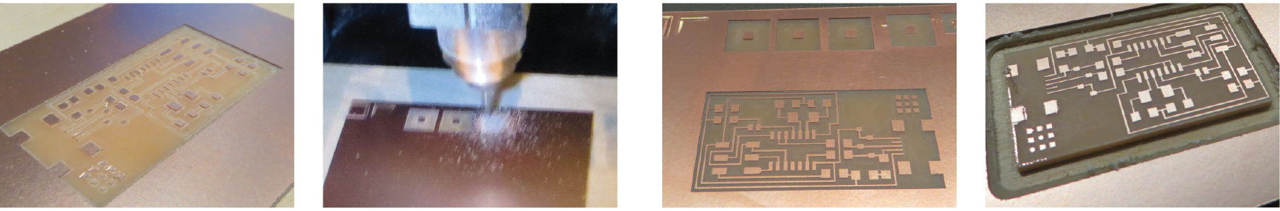 Attempt 1
Small testing areas
Attempt 2
Attempt 1
Small testing areas
Attempt 2
List of components
- J2 usb (connection)
- resistor 1 - 1k
- Diode 1 - 3.3V
- Diode 2 - 3.3V
- Resistor 2 - 499 Ohms
- Resistor 3 - 100 Ohms
- Resistor 4 - 100 Ohms
- S Jumper 2 - Zero Ohm Resistor
- IC1 - ITTINY44
- Crystal 20MHz
- Capacitor 2 - 10pF - pico
- Capacitor 3 - 10pF
- S Jumper 2 - Zero Ohm Resistor
- Capacitor 1 - 1uF - nano
- Resistor 5 - 10k
- J1 ISP - headers
Soldering
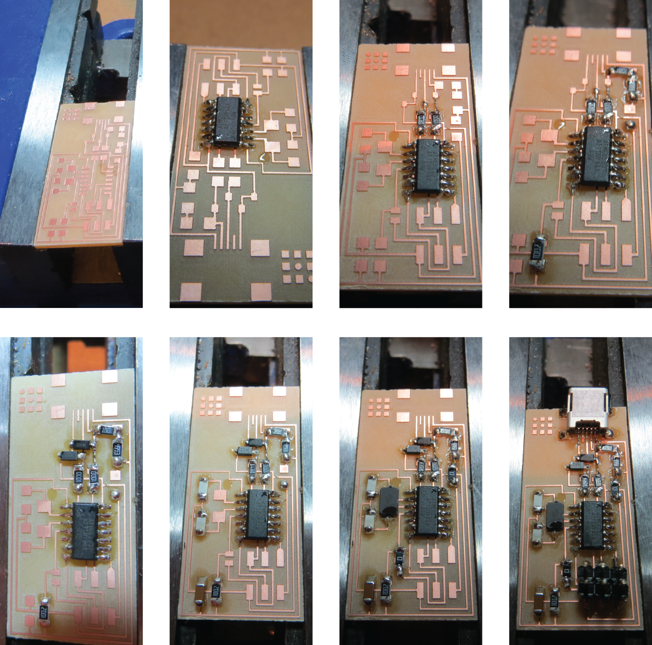
TIPS I APPLIED TO SOLDERING
- Start stuffing from the inside out (solder components on the inside of the board first)
- Use a small bit solder to hold a component in place, like glue (initially apply a small bit of solder to copper, then heat solder and put the component onto this using a tweezers)
- For legs or traces very close together apply more solder than required and then use the braid to take away unnecessary solder (especially solder that is connecting pieces it should be)
Week 4, Feb 13
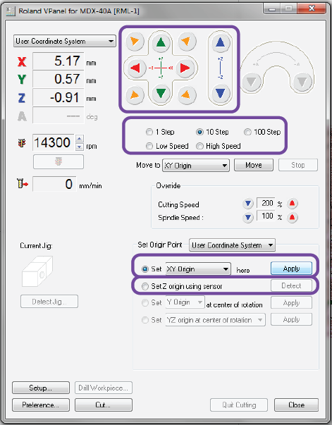
setting the origins
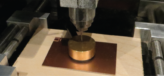
sensor
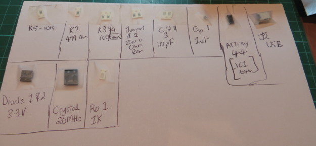
components for the board