Classes
  • Home Page


Principles and Practices
Project Management
Computer-aided design
Computer-controlled cutting
Electronics production
3D Scanning and Printing
Electronics design
Embedded Programming
Computer-controlled machining
Molding and Casting
Input Devices
Output Devices
Composites
Networking and Comunications
Interface and application programming
Applications and implications
Mechanical design, machine design
Invention, Intellectual Property, and Income
Final Project Development

Principles and practices
Project Management


The first lesson of Fab Acadamy 2015 was a presentation of course, the concept of Fab Lab and digital fabrication a first introduction of tools to build the web site that will contain my background, all my experience in Fab Academy and especially my final project.

I had never developed anything before Fab Academy and I had never even built a website. I built my site using a template bootstrap and then I developed it in html, with the use of CSS, through brackets. To better understand html and CSS I immediately looked for a nice template to open with brackets to modify it and check their effects. I quickly chose this template and from there I started to change the parts that interested me in terms of graphics and building the various pages to better document my Fab Academy
The other topic of the week but fundamental for the entire route of the Fab Academy has been the creation and management of the repository project. At OpenDot we used GitHub as a matter of easy and immediacy of use. We decided to manage all the commands from bash, then we synchronized the repository created by our tutor, entered the credentials from the terminal and did pull of ours Fab Academy folders.
The commands you use most often are:

  • git pull - in order to get an updated version of everything
  • git add (filename) - for selecting a specific file or
  • git add -A - in order to put all files or
  • git add -u - for selecting already tracked files that are modified
  • git commit -m "message" - for saving a commit in the local repository
  • git pull - in order to be sure that you have everything updated
  • git push - in order to send everything you commited to github

  • The last step of the first week was to define a concept of the final project. I thought of two projects:

  • The first project, aims to create a system that is able to track people movement in indoor space. Track means to measure movement point to point, stay time and people concentrations in critical point of rooms


  • Second project regards problems and defects in human posture and aims to create a wearable system that shows postural errors while walking, while standing and especially while sitting.

  • At the end I chose to develop my final project together with my colleague Youssef Bouali in order to produce a network of smart pots to monitor the health of plants

    Computer-aided design


    During second week , the task was to start from the sketch drawn to design the draft final project and achieve its design in 3d. Again, given my backgroud, I had to use sofware and concepts that I had never used before. The goal was to try, make mistakes and learn from more software as possible, both in 2D and in 3D. First I had to choose what to draw, as the project is not yet defined in detail. I decided to set up the project on a wearable device, so that people to track have with them a bracelet that I hope in the end could have a nice design. I've started to draw in 2D using Inksacape that at first glance I thought it was simple and effective for a beginner like me.


    Beyond the difficulty in obtaining a good quality file svg of FabLab logo, I managed to get an acceptable design in 2D. The next step, and the most complex, was to model the svg files in 3D. I mainly used blender and to do that I had to follow of course many video tutorials and guides found on line. With blender I extruded the files in 2D and especially I rotated the parts in the direction I wanted. Then I defined color of materials and tried to change the individual faces of the object created.


    In the last line I have also tried to realize the rendering of the image, but without animation and always using blender


    During the design phase, I also used FreeCAD. But failing to install the software on the Mac I had to use it on another computer windows. FreeCAD seemed very intuitive compared to Blender but once you pass the initial impact it seemed more complete.

    The last program I tried was Rhino. I re-extruded and fixed the svg file and then placed and rotated the logo. I fixed finally also the size of the bracelet and whole viewed as a solid object.


    The lesson learned is that blender is a very interesting software, as completely open, developed in python and definitely good for the non-geometric figures. Rhino, however, after an initial block in understanding all commands it seemed the best for geometrical figures to be realized in a simple and very precise way and also to fix non-geometric figures such as drawn in blender and then optimized in Rhino

    All the files are available for download here:


    Computer-controlled Cutting


    The week dedicated to learning cuttings tools was mainly focused on laser cutting and vinyl cutting. The objective was to provide an exercise by designing and cutting an object whose parts were modular and then assembled to achieve a structure in 3D. So designing in 2D to cut an object in 3D!


    Laser Cutting

    I started the week looking at some completed projects with cutting machines, mainly with laser cutting, to get inspired about my exercise. I focused my research on Thingiverse and Instructables and then some images on the web. At the end I decided to make a stand for my iPad.

    As for the previous week, to design in 2D I used Inkscape, following some tutorials to understand how to best set the edges and points to be embedded in a piece and another.

    During the design had to also consider the instructions of the lab regarding the thickness of the sheets (3mm) of wood to be used and the kerf (0,12mm) of the laser cutting machine. All this has been necessary to design in a correct way the joints between the various parts.

    Before proceeding to define the edges and save the file in pdf format and then proceed to cut, I entered the FabLab logo and text to engrave on the surface where it will be based the iPad

    After designing the stand, I continued with the cut. I saved the file in inkscape in dxf format and then i open it on Rhino (4 format) to start cutting. I had some problem with the speed of cutting, maybe because the wood sheet was deformed. So i had external lines cutted in some area and and not in other areas. To resove this problem i fixed a lower speed of cutting. An other problem was about the angle of a piece that overlaps the hole of another piece: a design problem. I learned that inkscape is a good software for design this kind of project but especially in case of design some angular holes it's better to use Rhino!

    Once i resolved design problems i cutted again my project and after i assembled it. This is the result:


    Vinyl Cutting

    During the exercise with the Vinyl Cutter I decided to make a sticker with the logo of my app Pipeline. So I started from the vector logo made previously and I opened in Inkscape to fill the logo design and save it in SVG and DXF
    Then I opened the project with Rhino to verify the accuracy of the drawing and in fact I had to fix it again before cutting
    Before the cut I had to save the file in EPS format to allow the machine to read through software SignBlazer. Unfortunately and strangely the file was not complete, so I had to first open it and save it with CoreDraw in CMX format
    The phase of the cut went according to plan: I set speed and pressure of the blade and booted the machine

    Vinyl Cutter from Claudio Pecere on Vimeo.

    The last step was to remove the excess with the help of a utility knife and apply transparent tape to paste in the future the final object on a surface. This is the final result

    All the files are available for download here:


    Electronics production


    During Week 4 the goal was to make a FabISP in-circuit program. To do this it was necessary to choose one of two FABISP proposed during the weekly class, milling the board and the circuit, soldering the components and program the final ISP.

    For my weekly assingment I choose the ISP with the resonator, the left one of the pictures above. The process to mill the board could be done by two different method: Using the milling machine or with a Laser Cutter able to cut the copper and engrave the traces of the board. In my lab, at OpenDot, we tried the second way, as the milling machine doesn't work. We used a Trotec Speedy 400 flexx to engrave the board, this machine has both CO2 and fiber laser technologies: 60 watt CO2 laser, 30 watt fiber laser. Here you can find the description of the process and experiments done in the lab on machinery.


    To make my FabISP i download first the board sugested during the lesson 4, the board with the resonetor component. After, I modify the file .png with Gimp to replace tha white border with a black one. Before start the cutting machine, I opened the board file with Inkscape to customize it with a vector part and to put a red line on the border for the cut level.The experiment done on the laser cutter

    The experiments on the laser cutter defined settings to be set on Trotec for a fine engraving of the board, so after setting right levels, power and number of cut steps (fiber to engrave and CO2 to cut), the production process could begin.

    After approximately half an hour, this is the final results. To remove the residue of the operation of engraving and cutting, I just passed the board gently with water and a sponge for prepared it to the soldering process of the components (following the Fab Academy Tutorials).


    This is the layout of the FabISP

    And these are the components necessary for the board:

  • n. 1 ATTiny 44 microcontroller
  • n. 1 Capacitor 1uF
  • n. 2 Resistor 100 ohm
  • n. 1 Resistor 499 ohm
  • n. 1 Resistor 1K ohm
  • n. 1 Resistor 10K
  • n. 1 6 pin header
  • n. 1 USB connector
  • n. 2 jumpers (1 soldering bridge and 1 of 0 ohm resistor)
  • n. 1 Resonator 20MHz
  • n. 2 Zener Diode 3.3 V
  • n. 2 6 pin connectors
  • The welding process of the components was completely newly for me because I had never used a welder in my life. After check with a tester that all the traces of my board was correctly engraved, I tied to solder the first component on a bad board and the results were not very satisfactory but with some exercises I was able to soldering all the components on my ISP correctly

    Once finished soldering I did the smoke test for a first check on the quality of the board: luckily everything was fine!


    Programming


    To programming the Fab ISP I needed:

  • another ISP, I used an ARDUINO UNO;
  • Avrdude to programming AVR microcontrollers
  • GCC, to compile C code, XCODE for Mac OS;
  • the FabISP firmware, Mac OS version available here;

  • Before starting programming i used the Arduino UNO as ISP, so when i load the scketch of ArduinoISP on Arduino IDE i had the right schema for connect Arduino 1 to FabISP

    With my mate Youssef Bouali, we prepared all the links of the Arduino UNO and then I started to programming the FabISP following the Tutorial

    Once connected the ArduinoUNO and FabISP, I edited the Makefile of the firmware to ensure that it works with our ISP. It was needed to open it and modify the following lines about AVRDUDE as showed below.

    Makefile
    #AVRDUDE = avrdude -c usbtiny -p $(DEVICE) # edit this line for your programmer AVRDUDE = avrdude -c stk500v1 -P /dev/cu.usbmodemfd121 -b19200 -p $(DEVICE) #AVRDUDE = avrdude -c avrisp2 -P usb -p $(DEVICE) # edit this line for your programmer


    To starting the programming process I had to navigate to the directory where I saved the FabISP firmware:

    MacBook-Air-di-Claudio:~ claudio$ cd Fabacademy/ MacBook-Air-di-Claudio:Fabacademy claudio$ cd fabISP_mac.0.8.2_firmware/ MacBook-Air-di-Claudio:fabISP_mac.0.8.2_firmware claudio$

    After command "Make clean"

    MacBook-Air-di-Claudio:fabISP_mac.0.8.2_firmware claudio$ make clean rm -f main.hex main.lst main.obj main.cof main.list main.map main.eep.hex main.elf *.o usbdrv/*.o main.s usbdrv/oddebug.s usbdrv/usbdrv.s

    Make hex

    MacBook-Air-di-Claudio:fabISP_mac.0.8.2_firmware claudio$ make hex avr-gcc -Wall -Os -DF_CPU=20000000 -Iusbdrv -I. -DDEBUG_LEVEL=0 -mmcu=attiny44 -c usbdrv/usbdrv.c -o usbdrv/usbdrv.o avr-gcc -Wall -Os -DF_CPU=20000000 -Iusbdrv -I. -DDEBUG_LEVEL=0 -mmcu=attiny44 -x assembler-with-cpp -c usbdrv/usbdrvasm.S -o usbdrv/usbdrvasm.o avr-gcc -Wall -Os -DF_CPU=20000000 -Iusbdrv -I. -DDEBUG_LEVEL=0 -mmcu=attiny44 -c usbdrv/oddebug.c -o usbdrv/oddebug.o avr-gcc -Wall -Os -DF_CPU=20000000 -Iusbdrv -I. -DDEBUG_LEVEL=0 -mmcu=attiny44 -c main.c -o main.o main.c:88:13: warning: always_inline function might not be inlinable [-Wattributes] static void delay ( void ) ^ avr-gcc -Wall -Os -DF_CPU=20000000 -Iusbdrv -I. -DDEBUG_LEVEL=0 -mmcu=attiny44 -o main.elf usbdrv/usbdrv.o usbdrv/usbdrvasm.o usbdrv/oddebug.o main.o rm -f main.hex main.eep.hex avr-objcopy -j .text -j .data -O ihex main.elf main.hex avr-size main.hex text data bss dec hex filename 0 1988 0 1988 7c4 main.hex

    Make fuse

    MacBook-Air-di-Claudio:fabISP_mac.0.8.2_firmware claudio$ Make fuse avrdude -c stk500v1 -P /dev/cu.usbmodemfd121 -b19200 -p attiny44 -U hfuse:w:0xDF:m -U lfuse:w:0xFF:m avrdude: AVR device initialized and ready to accept instructions Reading | ################################################## | 100% 0.05s avrdude: Device signature = 0x1e9207 avrdude: reading input file "0xDF" avrdude: writing hfuse (1 bytes): Writing | ################################################## | 100% 0.02s avrdude: 1 bytes of hfuse written avrdude: verifying hfuse memory against 0xDF: avrdude: load data hfuse data from input file 0xDF: avrdude: input file 0xDF contains 1 bytes avrdude: reading on-chip hfuse data: Reading | ################################################## | 100% 0.02s avrdude: verifying ... avrdude: 1 bytes of hfuse verified avrdude: reading input file "0xFF" avrdude: writing lfuse (1 bytes): Writing | ################################################## | 100% 0.02s avrdude: 1 bytes of lfuse written avrdude: verifying lfuse memory against 0xFF: avrdude: load data lfuse data from input file 0xFF: avrdude: input file 0xFF contains 1 bytes avrdude: reading on-chip lfuse data: Reading | ################################################## | 100% 0.02s avrdude: verifying ... avrdude: 1 bytes of lfuse verified avrdude: safemode: Fuses OK (E:FF, H:DF, L:FF) avrdude done. Thank you.

    And finally "make program"

    MacBook-Air-di-Claudio:fabISP_mac.0.8.2_firmware claudio$ make program avrdude -c stk500v1 -P /dev/cu.usbmodemfd121 -b19200 -p attiny44 -U flash:w:main.hex:i avrdude: AVR device initialized and ready to accept instructions Reading | ################################################## | 100% 0.05s avrdude: Device signature = 0x1e9207 avrdude: NOTE: "flash" memory has been specified, an erase cycle will be performed To disable this feature, specify the -D option. avrdude: erasing chip avrdude: reading input file "main.hex" avrdude: writing flash (1988 bytes): Writing | ################################################## | 100% 3.41s avrdude: 1988 bytes of flash written avrdude: verifying flash memory against main.hex: avrdude: load data flash data from input file main.hex: avrdude: input file main.hex contains 1988 bytes avrdude: reading on-chip flash data: Reading | ################################################## | 100% 2.26s avrdude: verifying ... avrdude: 1988 bytes of flash verified avrdude: safemode: Fuses OK (E:FF, H:DF, L:FF) avrdude done. Thank you. avrdude -c stk500v1 -P /dev/cu.usbmodemfd121 -b19200 -p attiny44 -U hfuse:w:0xDF:m -U lfuse:w:0xFF:m avrdude: AVR device initialized and ready to accept instructions Reading | ################################################## | 100% 0.05s avrdude: Device signature = 0x1e9207 avrdude: reading input file "0xDF" avrdude: writing hfuse (1 bytes): Writing | ################################################## | 100% 0.02s avrdude: 1 bytes of hfuse written avrdude: verifying hfuse memory against 0xDF: avrdude: load data hfuse data from input file 0xDF: avrdude: input file 0xDF contains 1 bytes avrdude: reading on-chip hfuse data: Reading | ################################################## | 100% 0.02s avrdude: verifying ... avrdude: 1 bytes of hfuse verified avrdude: reading input file "0xFF" avrdude: writing lfuse (1 bytes): Writing | ################################################## | 100% 0.02s avrdude: 1 bytes of lfuse written avrdude: verifying lfuse memory against 0xFF: avrdude: load data lfuse data from input file 0xFF: avrdude: input file 0xFF contains 1 bytes avrdude: reading on-chip lfuse data: Reading | ################################################## | 100% 0.02s avrdude: verifying ... avrdude: 1 bytes of lfuse verified avrdude: safemode: Fuses OK (E:FF, H:DF, L:FF) avrdude done. Thank you.

    Everything seems to be prefect but the last check to see if everything was fine it was to verify that the Mac had recognized my FabISP


    The last step of this week was to remove the soldering brigde and the 0 ohm resistor: now my FabISP it's completed and ready to by used as programmer to program other boards!!!

    3D Scanning and Printing


    The exercise of this week was to design and then print a small object in 3D and then scan and eventually print a real object. The first part of the exercise was achieved through Inkscape to draw the model in 2D. I wanted to create an object consisting of the 3D logo of Pipeline, a mobile App I developed in the last year. Is an object that maybe in the future I might change it into a keychain, maybe when my App becomes famous!


    After finishing the design in 2D on Inkscape I tried to make the model in 3D with SketchUp. Personally i think that this software is certainly easier to use but for a complex and professional design I think it is needed best software. So I saved my file in .dxf on Inkscape and then work it on SketchUp. This is the result of design process


    And this is the 3D printed final logo after loading .stl on Cura to generate the GCODE:


    Regarding the exercise of scanning of a real object, I used the Kinect to capture the image of myself through the use of Skanect.


    From Skanect I exported the file in .stl that presented some imperfections but overall a good definition. After I worked the file with blender to change the solid by removing unnecessary parts and excess, fix imperfections with the sculpture mode and modify individual points and add a base of support with my name.


    Once I loaded the file to print in Cura I noticed that inside 3D object there were some holes and the letters of my name needed some supports to make a good print. So i modified the file in Rhino, better of Blender for deleting mesh and to doing a boulean difference to embedded my name into the base of the object


    Below the printer process and the final result of my self!


    3D scan file is available for download here


    Other 3D files are available for download here:


    Electronics design


    The exercise of this week was to redraw the echo hello-world board and add (at least) a button and LED (with current-limiting resistor) check the design rules, and make it. As for the previous weeks I had to start my preparation beginning from 0. So I bought a book of electronics for beginners to become familiar with the basic principles of this discipline. Once learned the basics to perform the exercise I have been closely following the tutorial published in Fab Academy. The first step was to download eagle and begin to understand its characteristics. Later I added the libraries of components required.

    This is the final result with all component, led, button and links in the schematic view.

    Once finished the schematic i worked on the board to draw trace to link all the components. I tried to choose the function "autorouter" but i prefered to draw manually all the trace and understand the feature of eagle in this phase.


    Once I link all the traces I remove all layers except the top and i saved the file in .png and modified it in gimp with the parameters suggested in the previous tutorial.


    The last step was to enter a text and fill with white traces black. So the last image even if it expresses almost nothing, is the image to be used to realize materially the board with a milling machine. To make the hello board with Trotec Speedy 400 flexx to engrave the board, as I did for the FabISP assignment (week 4), i needed to mantain white the traces, black the background and to add in Inkscape the red level to cut the board.
    Setting and laser process of the board was the same of the FabISP
    And this is my first Hello Board, before and after soldering components!!!!

    All the files are available for download here:


    Embedded Programming


    During this week the assignment was learn to program the electronic board that we have produced in the previous module.

    The particular assignment of this was read the microcontroller data sheet, and to program the hello board to do something, with as many different programming languages and programming environments as possible. In previous module 6, we have designed the board to use the microcontroller Attiny44 and the related data sheet is the follow:

    To understand and programming my hello board i followed the tutorial suggested on Fab Aacademy. To programming the board I needed to download a precompiled program written in C that is composed by a folder with two files: the Makefile, which is used to automate the programming, and the file steadyled.c which is the program.
    The package I downloaded is composed of two files: the Makefile, which is used to automate the programming, and the file steadyled.c which is the program.

    Makefile
    PROJECT=steadyled SOURCES=$(PROJECT).c MMCU=attiny44 F_CPU = 20000000 CFLAGS=-mmcu=$(MMCU) -Wall -Os -DF_CPU=$(F_CPU) $(PROJECT).hex: $(PROJECT).out avr-objcopy -O ihex $(PROJECT).out $(PROJECT).c.hex;\ avr-size --mcu=$(MMCU) --format=avr $(PROJECT).out $(PROJECT).out: $(SOURCES) avr-gcc $(CFLAGS) -I./ -o $(PROJECT).out $(SOURCES) program-bsd: $(PROJECT).hex avrdude -p t44 -c bsd -U flash:w:$(PROJECT).c.hex program-dasa: $(PROJECT).hex avrdude -p t44 -P /dev/ttyUSB0 -c dasa -U flash:w:$(PROJECT).c.hex program-avrisp2: $(PROJECT).hex avrdude -p t44 -P usb -c avrisp2 -U flash:w:$(PROJECT).c.hex program-avrisp2-fuses: $(PROJECT).hex avrdude -p t44 -P usb -c avrisp2 -U lfuse:w:0x5E:m program-usbtiny: $(PROJECT).hex avrdude -p t44 -P usb -c usbtiny -U flash:w:$(PROJECT).c.hex program-usbtiny-fuses: $(PROJECT).hex avrdude -p t44 -P usb -c usbtiny -U lfuse:w:0x5E:m program-arduino: $(PROJECT).hex avrdude -p t44 -P com4 -b19200 -c stk500v1 -U flash:w:$(PROJECT).c.hex program-arduino-fuses: $(PROJECT).hex avrdude -p t44 -P com4 -b19200 -c stk500v1 -U lfuse:w:0x5E:m program-dragon: $(PROJECT).hex avrdude -p t44 -P usb -c dragon_isp -U flash:w:$(PROJECT).c.hex

    Before going further with programming the board, I had to modify the following two lines in order to specify to which pins the button and led are connected:
    #define BUTTON_BIT PA3
    #define LED_BIT PA7

    steadyled.c
    #include <avr/io.h> #include <inttypes.h> #include <util/delay.h> void delay_ms(uint16_t ms); void init_io(); int button_is_pressed(); void toggle_led(); #define F_CPU 20000000UL /* 20MHz crystal oscillator */ #define BUTTON_PORT PORTA /* PORTx - register for button output */ #define BUTTON_PIN PINA /* PINx - register for button input */ #define BUTTON_BIT PA3 /* bit for button input/output */ #define LED_PORT PORTA /* PORTx - register for LED output */ #define LED_BIT PA7 /* bit for button input/output */ #define LED_DDR DDRA /* LED data direction register */ #define DEBOUNCE_TIME 25 /* time to wait while "de-bouncing" button */ #define LOCK_INPUT_TIME 250 /* time to wait after a button press */ int main (void) { init_io(); while (1) { if (button_is_pressed()) { toggle_led(); } } } void delay_ms(uint16_t ms) { while ( ms ) { _delay_ms(1); ms--; } } void init_io() { /* set LED pin as digital output */ LED_DDR = _BV (LED_BIT); /* led is OFF initially (set pin high) */ LED_PORT |= _BV(LED_BIT); /* turn on internal pull-up resistor for the switch */ BUTTON_PORT |= _BV(BUTTON_BIT); } int button_is_pressed() { /* the button is pressed when BUTTON_BIT is clear */ if (bit_is_clear(BUTTON_PIN, BUTTON_BIT)) { delay_ms(DEBOUNCE_TIME); if (bit_is_clear(BUTTON_PIN, BUTTON_BIT)) return 1; } return 0; } void toggle_led() { LED_PORT ^= _BV(LED_BIT); }

    So I connected the Hello board to the FabISP using the rainbow cable through the 6 Pins, and both boards to my computer through FDTI cable via USB ports:

    Now I opened the terminal and changed command line to the directory of where my Makefile and C code are. So I executed the command "make" in order to create the execute file of the Makefile. The Makefile creates by default the hexadecimal file (steadyled.c.hex)

    MacBook-Air-di-Claudio:~ claudio$ cd Fabacademy/ MacBook-Air-di-Claudio:Fabacademy claudio$ cd steadyled> make avr-gcc -mmcu=attiny44 -Wall -Os -DF_CPU=20000000 -I./ -o steadyled.out steadyled.c steadyled.c:10:0: warning: "F_CPU" redefined #define F_CPU 20000000UL /* 20MHz crystal oscillator */ ^ <command-line>:0:0: note: this is the location of the previous definition avr-objcopy -O ihex steadyled.out steadyled.c.hex;\ avr-size --mcu=attiny44 --format=avr steadyled.out AVR Memory Usage ---------------- Device: attiny44 Program: 140 bytes (3.4% Full) (.text + .data + .bootloader) Data: 0 bytes (0.0% Full) (.data + .bss + .noinit)

    Now in the same folder I saved the stadyled file, I found the new files to programming the board. After that, I have launched the command "make program-usbtiny-fuses" to reset the microcontroller and prepare it to receive the programming:

    MacBook-Air-di-Claudio:steadyled claudio$> make program-usbtiny-fuses avr-objcopy -O ihex steadyled.out steadyled.c.hex;\ avr-size --mcu=attiny44 --format=avr steadyled.out AVR Memory Usage ---------------- Device: attiny44 Program: 140 bytes (3.4% Full) (.text + .data + .bootloader) Data: 0 bytes (0.0% Full) (.data + .bss + .noinit) avrdude -p t44 -P usb -c usbtiny -U lfuse:w:0x5E:m avrdude: AVR device initialized and ready to accept instructions Reading | ################################################## | 100% 0.00s avrdude: Device signature = 0x1e9207 avrdude: reading input file "0x5E" avrdude: writing lfuse (1 bytes): Writing | ################################################## | 100% 0.00s avrdude: 1 bytes of lfuse written avrdude: verifying lfuse memory against 0x5E: avrdude: load data lfuse data from input file 0x5E: avrdude: input file 0x5E contains 1 bytes avrdude: reading on-chip lfuse data: Reading | ################################################## | 100% 0.00s avrdude: verifying ... avrdude: 1 bytes of lfuse verified avrdude: safemode: Fuses OK (E:FF, H:DF, L:5E) avrdude done. Thank you.

    The last step was launched the command "make program-usbtiny" in order to program the Hello board:

    MacBook-Air-di-Claudio:steadyled claudio$ make program-usbtiny avr-objcopy -O ihex steadyled.out steadyled.c.hex;\ avr-size --mcu=attiny44 --format=avr steadyled.out AVR Memory Usage ---------------- Device: attiny44 Program: 140 bytes (3.4% Full) (.text + .data + .bootloader) Data: 0 bytes (0.0% Full) (.data + .bss + .noinit) avrdude -p t44 -P usb -c usbtiny -U flash:w:steadyled.c.hex avrdude: AVR device initialized and ready to accept instructions Reading | ################################################## | 100% 0.01s avrdude: Device signature = 0x1e9207 avrdude: NOTE: "flash" memory has been specified, an erase cycle will be performed To disable this feature, specify the -D option. avrdude: erasing chip avrdude: reading input file "steadyled.c.hex" avrdude: input file steadyled.c.hex auto detected as Intel Hex avrdude: writing flash (140 bytes): Writing | ################################################## | 100% 0.26s avrdude: 140 bytes of flash written avrdude: verifying flash memory against steadyled.c.hex: avrdude: load data flash data from input file steadyled.c.hex: avrdude: input file steadyled.c.hex auto detected as Intel Hex avrdude: input file steadyled.c.hex contains 140 bytes avrdude: reading on-chip flash data: Reading | ################################################## | 100% 0.43s avrdude: verifying ... avrdude: 140 bytes of flash verified avrdude: safemode: Fuses OK (E:FF, H:DF, L:5E) avrdude done. Thank you.

    At this level, the LED should turn on by clicking on the button: this means that the board is working properly and it has been programmed successfully. Luckily my board works well!

    The Makefile and C program are available for download here:

    Computer-Controlled Machining


    The exercise of this week was to build something big, drawing it and then producing it through the the CNC machine. The idea was to build something to give to my nieces, something that would be useful and would last (I would not bet on this;)). So I thought of a stool and having been inspired by some of the projects I started drawing in Rhino. The reference to the holes was obviously the thick sheet of wood which in my case was of 12mm

    Once finished drawing I set the levels of milling that, having no parts to be engraved, were only two: red for external cut and blue for internal cut

    Last step of drawing was the check about the join parts. To control if all parts fit correctly with holes, I extruded all the pieces and then I lined up as a 3D model. Through this step I realized that the design was well done


    The next step was to load the .dxf on VCarv pro before sending it to cnc machine, in my case a Shopbot. The first step was to define the dimension of the wood sheet: 2100X1440mm and 12mm thickness of the wood and the size of the tools

    I have after set the levels of internal and external cut and viewed everything the preview set of VCarve

    The last step was to mill the pieces with Shopbot. Before starting the Shopbot, I set the Z axis and than I lauched the CNC

    Shopbot starts working from Claudio Pecere on Vimeo

    Once the shopbots has finished its work, I removed the pieces from the sheet of wood with a chisel. I immediately noticed some imperfections within the holes, it looked as if the CNC had drawn tabs even within the parties to pierce completely. I removed also this parts Finally I can start to assembly all parts and this is the final result of my stool that now is used by my bonsai elm

    All the files are available for download here:


    Molding and Casting


    This week the exercise concerned the realization of a mold designed by us then to use it with the resins and produce the cast. In our lab we have the wax, to be milled with a small milling. For the task this week I wanted to reproduce the mold of the logo of my app for smartphones, Pipeline. I therefore started drawing the slab of wax on which mill the object and after, starting from the vector logo made of inkscape, I fixed the object, I extruded and put it at the center of the wax.


    One finished, I tried to make a simple render to replicate the colour of wax to mill, this is the final results

    The next step was to mill the wax with a milling machine. Unfortunately in our lab we did not have this machine so we used the shop bot to mill the wax. The first step was to determine the settings of milling on the ShopBot Partworks3D. I decided to use before a tip from 0.6mm for a first milling and the tip of 0.3mm for the finishings. Later I have fixed and placed the block of wax with pieces of wood, placed the tip and the machine and launched the action of milling.

    Milling wax from Claudio Pecere on Vimeo.


    The first pass with the biggest tip was fine. I recovered wax milled for reuse and change the tip for the finishing touches. At this stage, something went wrong, surely the milling speed, so the smaller tip has broken and I had to stop drilling before the completion of the project.

    And this is the final results, and the recovered wax, before starting use the silicon rubber on the wax
    he last step concerns the use of the wax to make the mold and subsequently make the cast of the object. To create the mold, I used the silicone rubber AL20 medium hardness and high tear resistance. It 'a liquid bicomponent gray color, for mixing I diluted 5% of catalyst in the liquid rubber by using a precision balance and mix well for 2 minutes
    Once you have the correct fluid to spill into the mold of wax I brushed the surface to prevent the formation of air bubbles and then I started to pour the silicone rubber slowly, making it fall into the holes and then continuing coverage trying to bring down the liquid from a very high position to avoid air bubbles.
    You must wait 24 hours for a complete drying of rubber, to be sure I waited 48h before removing the wax. The result was very satisfactory despite the mold with wax was not accurate. No air bubbles and excellent performance of the material: now I am ready to make the cast!
    I decided to use gypsum for casting in the mold, both for economic reasons and for speed of drying. I was surprised by the quality of the scagliola (a type of gypsum less crude and more suitable for precision molds). This is the final result:

    All the files are available for download here:


    Input devices


    This week the assignment was to measure something: add a sensor to a microcontroller board that you've designed and read it. I made to board following the satshakit of my mate Daniele Ingrassia
    For the exercise I decided to measure the soil moisture of my plants. It 's really simple to build a humidity sensor but to save time I have decided to use a sensor already made This is the sketch used for the exercise

    Sketch Soil Moisture Sensor
    void setup(){ Serial.begin(9600); } void loop() { int sensorReading= analogRead(A0); //reads the sensor value Serial.print("sensor = " ); Serial.println (sensorReading); //prints out the sensor reading //if (sensorReading > 800){//if reading is above 800, LED blinks on and off //digitalWrite(LED,HIGH); //turns the LED on //delay(1000); //waits for a second //digitalWrite(LED,LOW); //turns the LED off delay(1000); //waits for a second }

    The image easily explains how to connect the sensor to the Arduino, from here it is easy to connect also satshakit.
    The next was to insert the sensor in the soil and try to measure the moisture. This is the final result:

    Moisture Sensor - Input Devices from Claudio Pecere on Vimeo.

    The sketch for Moisture sensor is available for download here:


    Output devices


    This week the exercise was to add an output device to a microcontroller board you've designed and program it to do something. For this exercise I used a 7-segment display with four digits to be connected to satshakit through a breadbord These are simple images that shows how is made this kind of display and how to connect to a microcontroller

    And these are the right links between microcontroller and display

  • ARDUINO Pin 1 - Display Pin 10 (a)
  • ARDUINO Pin 2 - Display Pin 7 (b)
  • ARDUINO Pin 3 - Display Pin 4 (c)
  • ARDUINO Pin 4 - Display Pin 2 (d)
  • ARDUINO Pin 5 - Display Pin 1 (e)
  • ARDUINO Pin 6 - Display Pin 11 (f)
  • ARDUINO Pin 7 - Display Pin 5 (g)
  • ARDUINO Pin 8 - Display Pin 3 (dot)
  • ARDUINO Pin 9 - Display Pin 12 with resistor 1K (d1)
  • ARDUINO Pin 10 - Display Pin 9 with resistor 1K (d2)
  • ARDUINO Pin 11 - Display Pin 8 with resistor 1K (d3)
  • ARDUINO Pin 12 - Display Pin 6 with resistor 1K (d4)

  • This is the sketch used for the exercise of Output devices

    Sketch Soil Moisture Sensor
    //segments int a = 1; int b = 2; int c = 3; int d = 4; int e = 5; int f = 6; int g = 7; int p = 8; //digits int d4 = 9; int d3 = 10; int d2 = 11; int d1 = 12; //other int del = 100; int buttoncount = 0; int loopcount = 0; void setup() { pinMode(d1, OUTPUT); pinMode(d2, OUTPUT); pinMode(d3, OUTPUT); pinMode(d4, OUTPUT); pinMode(a, OUTPUT); pinMode(b, OUTPUT); pinMode(c, OUTPUT); pinMode(d, OUTPUT); pinMode(e, OUTPUT); pinMode(f, OUTPUT); pinMode(g, OUTPUT); pinMode(p, OUTPUT); digitalWrite(a, HIGH); digitalWrite(b, HIGH); digitalWrite(c, HIGH); digitalWrite(d, HIGH); digitalWrite(e, HIGH); digitalWrite(f, HIGH); digitalWrite(g, HIGH); digitalWrite(p, HIGH); } void loop() { roulette(4); delay(100); zigzag(2); delay(100); circles(4); delay(100); } void pickDigit(int x) { digitalWrite(d1, LOW); digitalWrite(d2, LOW); digitalWrite(d3, LOW); digitalWrite(d4, LOW); switch(x) { case 1: digitalWrite(d1, HIGH); break; case 2: digitalWrite(d2, HIGH); break; case 3: digitalWrite(d3, HIGH); break; default: digitalWrite(d4, HIGH); break; } } void clearLEDs() { digitalWrite(a, HIGH); digitalWrite(b, HIGH); digitalWrite(c, HIGH); digitalWrite(d, HIGH); digitalWrite(e, HIGH); digitalWrite(f, HIGH); digitalWrite(g, HIGH); digitalWrite(p, HIGH); } void roulette(int x) { loopcount = 0; while (loopcount < x) { digitalWrite(a, LOW); pickDigit(1); delay(del); pickDigit(2); delay(del); pickDigit(3); delay(del); pickDigit(4); delay(del); digitalWrite(a, HIGH); digitalWrite(b, LOW); delay(del); digitalWrite(b, HIGH); digitalWrite(c, LOW); delay(del); digitalWrite(c, HIGH); digitalWrite(d, LOW); delay(del); pickDigit(3); delay(del); pickDigit(2); delay(del); pickDigit(1); delay(del); digitalWrite(d, HIGH); digitalWrite(e, LOW); delay(del); digitalWrite(e, HIGH); digitalWrite(f, LOW); delay(del); clearLEDs(); loopcount++; } } void zigzag(int x) { loopcount = 0; while(loopcount < x) { digitalWrite(a, LOW); pickDigit(1); delay(del); pickDigit(2); delay(del); pickDigit(3); delay(del); pickDigit(4); delay(del); digitalWrite(a, HIGH); digitalWrite(b, LOW); delay(del); digitalWrite(b, HIGH); digitalWrite(g, LOW); delay(del); pickDigit(3); delay(del); pickDigit(2); delay(del); pickDigit(1); delay(del); digitalWrite(g, HIGH); digitalWrite(e, LOW); delay(del); digitalWrite(e, HIGH); digitalWrite(d, LOW); delay(del); pickDigit(2); delay(del); pickDigit(3); delay(del); pickDigit(4); delay(del); digitalWrite(d, HIGH); digitalWrite(c, LOW); delay(del); digitalWrite(c, HIGH); digitalWrite(g, LOW); delay(del); pickDigit(3); delay(del); pickDigit(2); delay(del); pickDigit(1); delay(del); digitalWrite(g, HIGH); digitalWrite(f, LOW); delay(del); clearLEDs(); loopcount++; } } void circles(int x) { loopcount = 0; while (loopcount < x) { digitalWrite(a, LOW); digitalWrite(b, LOW); digitalWrite(f, LOW); digitalWrite(g, LOW); pickDigit(1); delay(250); digitalWrite(a, HIGH); digitalWrite(b, HIGH); digitalWrite(f, HIGH); digitalWrite(c, LOW); digitalWrite(d, LOW); digitalWrite(e, LOW); pickDigit(2); delay(250); digitalWrite(a, LOW); digitalWrite(b, LOW); digitalWrite(f, LOW); digitalWrite(c, HIGH); digitalWrite(d, HIGH); digitalWrite(e, HIGH); pickDigit(3); delay(250); digitalWrite(a, HIGH); digitalWrite(b, HIGH); digitalWrite(f, HIGH); digitalWrite(c, LOW); digitalWrite(d, LOW); digitalWrite(e, LOW); pickDigit(4); delay(250); clearLEDs(); loopcount++; } }

    The next step was to connect the display to satshakit and load the sketch, I choose an animation for the display for single segment

    Display 7 segment 4 digit animation from Claudio Pecere on Vimeo.

    The sketch for the animation is available for download here:


    Composites


    The goal of this week was to Design and make a 3D mold (~ft2), and produce a fiber composite part in it. During the week, I tried to draw more projects to do the exercise but at the end I decided to produce a long board taking inspiration from some models found on the web. My goal was to produce a longboard to give to a friend very passionate about these objects. I have therefore designed the board on Rhino with the aim of producing with the laser cut, three equal pieces of 4 mm to be assembled by means of composite materials.

    This was the phase of laser cutting:

    Laser on Longboard from Claudio Pecere on Vimeo.


    The next step was make the final longboard using fiber and bicomponent epoxy resin mixed 1:2. I glued all the layer using fiber and resin and taking care not to leave air bubbles or gaps between the levels of wood I mixed components following the indications mixing for about 2 minutes in a container off to avoid the formation of a liquid non-homogeneous


    The next step was to locate and secure the board on the mold previously prepared by Gianluca Pugliese to give the right angle to the longboard

    When I finished with the resin and fiber I waited 12 hours that the composite material dried out completely. After I started the stage of removing the excess parts first with scissors then with a dremel and then sanding the corners of the board.This was a particularly fatiguing process because the composite material excess was very hard to remove

    Once I finished I performed a test of strength of the board and fortunately everything went pretty well!

    Load resistance Test from Claudio Pecere on Vimeo.


    The last step was to assembly truck and wheels to my longboard, I used components reused but still functional and useful to create a true longboard:

    Finally the board is ready for use!!!

    Trying longboard from Claudio Pecere on Vimeo.

    The longboard file is available for download here:


    Networking and communications


    For this week we have to design and build a wired and/or wireless network connecting at least two processors. To realize the exercise I used a communication device very cheap but very powerful. it's a very inexpensive radio module, that provide a robust interface for Transferring data wirelessly between devices with minimal resource and power consumption. In addition to this, it is a module of communication often used, easy to find good libraries and many examples of use It is difficult to choose which library to use as there are lots of on the web. This is the most used. The first step was to connect pins: each device has 8 but only 7 are those to be used, at least for most of the cases. This is the disposition of the Pin:
    Given that I'm a beginner I started from the examples proposed in getting started. Very simple, it was enough to connect the pin to the module as the following list and load the Getting Started sketch of the two microcontrollers:

    These are the right links between microcontroller and RF24 (RF24 Pin8 not linked)

  • ARDUINO GND - RF24 Pin 1
  • ARDUINO 3.3V - RF24 Pin 2
  • ARDUINO Pin 9 - RF24 Pin 3
  • ARDUINO Pin 10 - RF24 Pin 4
  • ARDUINO Pin 13 - RF24 Pin 5
  • ARDUINO Pin 11 - RF24 Pin 6
  • ARDUINO Pin 12 - RF24 Pin 7

  • Once loaded the sketch on both microcontrollers, with two parallel sessions of Arduino IDE, if all is ok you should see this result in both monitors serial

    Getting Started First Print
    RF24/examples/GettingStarted/ ROLE: Pong back STATUS = 0x0e RX_DR=0 TX_DS=0 MAX_RT=0 RX_P_NO=7 TX_FULL=0 RX_ADDR_P0-1 = 0xf0f0f0f0d2 0xf0f0f0f0e1 RX_ADDR_P2-5 = 0xc3 0xc4 0xc5 0xc6 TX_ADDR = 0xf0f0f0f0d2 RX_PW_P0-6 = 0x08 0x08 0x00 0x00 0x00 0x00 EN_AA = 0x3f EN_RXADDR = 0x03 RF_CH = 0x4c RF_SETUP = 0x07 CONFIG = 0x0f DYNPD/FEATURE = 0x00 0x00 Data Rate = 1MBPS Model = nRF24L01 CRC Length = 16 bits PA Power = PA_HIGH }

    Last step is to choose which is receiving and which transmitter with T or R. The result is this:

    Getting Started Networking from Claudio Pecere on Vimeo.

    .


    The next step was to try and send a text message from one module to another and modify it in real time. The connections have remained unchanged instead I loaded two different codes on the two microcontrollers.

    Sending Message Transmitter Sketch
    #include <SPI.h> #include <nRF24L01.h> #include <RF24.h> #include <RF24_config.h> /* This sketch sends a string to a corresponding Arduino with nrf24 attached. It appends a specific value (2 in this case) to the end to signify the end of the message. */ int msg[1]; RF24 radio(9,10); const uint64_t pipe = 0xE8E8F0F0E1LL; void setup(void){ Serial.begin(9600); radio.begin(); radio.openWritingPipe(pipe);} void loop(void){ String theMessage = "Hi Claudio"; Serial.print("Transmitter just sent message:"); Serial.println(theMessage); int messageSize = theMessage.length(); for (int i = 0; i < messageSize; i++) { int charToSend[1]; charToSend[0] = theMessage.charAt(i); radio.write(charToSend,1); } //send the 'terminate string' value... msg[0] = 2; radio.write(msg,1); /*delay sending for a short period of time. radio.powerDown()/radio.powerupp //with a delay in between have worked well for this purpose(just using delay seems to //interrupt the transmission start). However, this method could still be improved as I still get the first character 'cut-off' sometimes. I have a 'checksum' function on the receiver to verify the message was successfully sent. */ radio.powerDown(); delay(1000); radio.powerUp(); }
    Sending Message Receiving Sketch
    #include <SPI.h> #include <nRF24L01.h> #include <RF24.h> #include <RF24_config.h> #include <SPI.h> /* This sketch receives strings from sending unit via nrf24 and prints them out via serial. The sketch waits until it receives a specific value (2 in this case), then it prints the complete message and clears the message buffer. */ int msg[1]; RF24 radio(9,10); const uint64_t pipe = 0xE8E8F0F0E1LL; int lastmsg = 1; String theMessage = "ciao"; void setup(void){ Serial.begin(9600); radio.begin(); radio.openReadingPipe(1,pipe); radio.startListening(); } void loop(void){ if (radio.available()){ bool done = false; done = radio.read(msg, 1); char theChar = msg[0]; if (msg[0] != 2){ theMessage.concat(theChar); } else { Serial.print("Receiver just received message:"); Serial.println(theMessage); theMessage= ""; } } }

    This Video show the final result:

    Sending Text with RF24 Module from Claudio Pecere on Vimeo.

    The sketch files are availables for download here:


    Interface and application programming


    This week the assignment was to write an application that interfaces with an input and/or output device. The initial idea was to use one of the sensors used in the previous weeks to write an application that would show the measured data and printing on an interface to be used also in the final project. That's why I chose to use a humidity sensor and air temperature humidity sensor and air temperature The first step was to connect the sensor to satshakit following the directions of Arduino UNO.
    After that I tried the operation of the sensor only temperature, through a simple sketch loaded on ARDUINO IDE just after install the right libraries of DHT11.

    Temperature Sketch
    #include <dht.h> #include <DHT.h> #include <dht11.h> #include <DHT.h> dht11 DHT; #define DHT11_PIN 4 void setup(){ Serial.begin(9600); // Serial.println("DHT TEST PROGRAM "); //Serial.print("LIBRARY VERSION: "); //Serial.println(DHT11LIB_VERSION); //Serial.println(); //Serial.println("Type,\tstatus,\tHumidity (%),\tTemperature (C)"); } void loop(){ int chk; //Serial.print("DHT11, \t"); chk = DHT.read(DHT11_PIN); // READ DATA switch (chk){ case DHTLIB_OK: // Serial.print("OK,\t"); break; case DHTLIB_ERROR_CHECKSUM: Serial.print("Checksum error,\t"); break; case DHTLIB_ERROR_TIMEOUT: Serial.print("Time out error,\t"); break; default: Serial.print("Unknown error,\t"); break; } // DISPLAT DATA //Serial.print(DHT.humidity,1); //Serial.print(",\t"); double sensor = DHT.temperature; Serial.println(sensor); Serial.print(","); Serial.flush(); delay(1000); }

    Luckily the sensor works, and this is the measurement printed on the monitor serial


    The next step was to write the application for an interface from which to display the measurement of the sensor. This part will be used for the final project. To create the interface I used QT, software that I found it very intuitive and easy to use for a beginner like me. The application has been written in C++


    I found some problems in the recognition of the serial ports of the microcontroller which effectively impeded the application from running. This is a type of problem but manifests itself depending on the operating system from which threw the interface. With windows the result was easy to obtain


    Temperature Application interface
    #include "dialog.h" #include "ui_dialog.h" #include <QSerialPort> #include <QSerialPortInfo> #include <string> #include <QDebug> #include <QMessageBox> Dialog::Dialog(QWidget *parent) : QDialog(parent), ui(new Ui::Dialog) { ui->setupUi(this); ui->temp_lcdNumber->display("26.50 C"); arduino = new QSerialPort(this); serialBuffer = ""; parsed_data = ""; temperature_value = 0.0; /* * Testing code, prints the description, vendor id, and product id of all ports. * Used it to determine the values for the arduino uno. * **/ qDebug() << "Number of ports: " << QSerialPortInfo::availablePorts().length() << "\n"; foreach(const QSerialPortInfo &serialPortInfo, QSerialPortInfo::availablePorts()){ qDebug() << "Description: " << serialPortInfo.description() << "\n"; qDebug() << "Has vendor id?: " << serialPortInfo.hasVendorIdentifier() << "\n"; qDebug() << "Vendor ID: " << serialPortInfo.vendorIdentifier() << "\n"; qDebug() << "Has product id?: " << serialPortInfo.hasProductIdentifier() << "\n"; qDebug() << "Product ID: " << serialPortInfo.productIdentifier() << "\n"; } /* * Identify the port the arduino uno is on. */ bool arduino_is_available = false; QString arduino_uno_port_name; // // For each available serial port foreach(const QSerialPortInfo &serialPortInfo, QSerialPortInfo::availablePorts()){ // check if the serialport has both a product identifier and a vendor identifier if(serialPortInfo.hasProductIdentifier() && serialPortInfo.hasVendorIdentifier()){ // check if the product ID and the vendor ID match those of the arduino uno if((serialPortInfo.productIdentifier() == arduino_uno_product_id) && (serialPortInfo.vendorIdentifier() == arduino_uno_vendor_id)){ arduino_is_available = true; // arduino uno is available on this port arduino_uno_port_name = serialPortInfo.portName(); } } } /* * Open and configure the arduino port if available */ if(arduino_is_available){ qDebug() << "Found the arduino port...\n"; arduino->setPortName(arduino_uno_port_name); arduino->open(QSerialPort::ReadOnly); arduino->setBaudRate(QSerialPort::Baud9600); arduino->setDataBits(QSerialPort::Data8); arduino->setFlowControl(QSerialPort::NoFlowControl); arduino->setParity(QSerialPort::NoParity); arduino->setStopBits(QSerialPort::OneStop); QObject::connect(arduino, SIGNAL(readyRead()), this, SLOT(readSerial())); }else{ qDebug() << "Couldn't find the correct port for the arduino.\n"; QMessageBox::information(this, "Serial Port Error", "Couldn't open serial port to arduino."); } } Dialog::~Dialog() { if(arduino->isOpen()){ arduino->close(); // Close the serial port if it's open. } delete ui; } void Dialog::readSerial() { qDebug() << "Open Serial port"; /* * readyRead() doesn't guarantee that the entire message will be received all at once. * The message can arrive split into parts. Need to buffer the serial data and then parse for the temperature value. * */ QStringList buffer_split = serialBuffer.split(","); // split the serialBuffer string, parsing with ',' as the separator // Check to see if there less than 3 tokens in buffer_split. // If there are at least 3 then this means there were 2 commas, // means there is a parsed temperature value as the second token (between 2 commas) if(buffer_split.length() < 3){ // no parsed value yet so continue accumulating bytes from serial in the buffer. serialData = arduino->readAll(); serialBuffer = serialBuffer + QString::fromStdString(serialData.toStdString()); serialData.clear(); }else{ // the second element of buffer_split is parsed correctly, update the temperature value on temp_lcdNumber serialBuffer = ""; qDebug() << buffer_split << "\n"; parsed_data = buffer_split[1]; temperature_value = parsed_data.toDouble(); // convert to fahrenheit qDebug() << "TEST2"; qDebug() << "Temperature: " << temperature_value << "\n"; parsed_data = QString::number(temperature_value, 'g', 4); // format precision of temperature_value to 4 digits or fewer Dialog::updateTemperature(parsed_data); } } void Dialog::updateTemperature(QString sensor_reading) { // update the value displayed on the lcdNumber ui->temp_lcdNumber->display(sensor_reading); }

    Finally, this video shows the final result:

    Testing Temperature Application Interface from Claudio Pecere on Vimeo.

    .

    The temperature sketch and the project with the code in C++ of the application interface are availables for download here


    Applications and Implications


    Final Project Idea

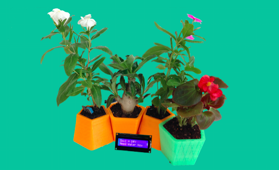
    The goal of this final project is to provide a modular and smart pots system, easy to produce, cheap and with a pleasant and useful interface. This final project is carried out in collaboration between Youssef Bouali and Claudio Pecere

    What will it do?

    The idea is to create a series of modular and intelligent pots. We want to combine the look of the design of multiple objects (maybe 5) modular and interchangeable, and the sensors and electronics in order to monitor the health status of various plants.

    Who's done what beforehand?

    The idea was born from the need to monitor and possibly interact with plants from a distance. There are many projects related to the monitoring of the health of plants, some born in the Fab Lab or at least inspired by the DIY philosophy, others that are already commercial products for small indoor culture. Also during the week we have heard of other similar projects within the Fab Academy on which there was a brief exchange of views on deepening maybe at the end of the course. These are the current project in this field:

  • Parrot Flower Power: Monitoring of humidity, brightness, temperature, fertilizer with app for smartphone connected via Bluetooth
  • Hydroponic House System: This project has bee developed by Medaarch Fab Lab. The project was designed for the cultivation of plants in hydroponic vegetables and small in size. The system is composed of a structure for the germination, from a control apparatus of the quality of the cultivation (light, pH, temperature and humidity) and by a distribution system and water recirculation.
  • InternetOfGreens: This project has bee developed by WeMake Fab Lab . The main features are: The garden controlled by Arduino for cultivation using hydroponics; Sensors with integrated data environment SmartCitizen project; Data visualization via web app; Ph control water; Management cycles on / off lamps; Management irrigation cycles; Management cycle fertilization water
  • Ortocubo: The prototype is equipped with a high-tech hardware and software used for the monitoring and regulation of nutrients and environmental parameters essential for the proper growth of the plant, such as temperature, humidity, light and pH. The sensors and actuators integrated in the module ensure that the plants they are always in the optimal conditions for the growth, lowering the time of cultivation and reducing waste to a minimum
  • What materials and components will be required?

  • PLA 1,75 mm for fabricate Pots by 3D Printing
  • Soil Moisture Sensor
  • Microcontroller for the main board and related components
  • Umidity sensor
  • Temperature Sensor
  • RF24 to comunicate data (optional)
  • Wifi module to send data to a server for the web app (optional)
  • display LCD hd44780
  • Where will they come from?

    The pla is present in the lab purchased from national suppliers. The sensors were purchased from the web, mainly from amazon and ebay. The sensors were purchased from Farnel while the board is that developed by Daniele Ingrassia: satshakit, fabricated with the laser machine in the lab and assembled with its components

    How much will it cost?

  • PLA 1,75 mm for fabricate Pots by 3D Printing - for each pot it takes about 70 grams of pla for an average cost of about 1,75€
  • Soil Moisture Sensor - 3€
  • Microcontroller for the main board and related components - as indicated by Daniele Ingrassia in the BOM of satshakit 9,06€
  • Umidity sensor and Temperature Sensor - 4€
  • RF24 to comunicate data - 6€
  • display LCD hd44780 - 4€
  • Total cost for materials and for each pot it's about 27,81€

    What parts and systems will be made?

    Will be produced the physical part of the pot, the board will be produced which will then be completely assembled with all the parts. The sensors can expect instead purchased.Will be developed both the software, able to process sensor data and display them on the display, and both the 3D model of the pot

    What processes will be used?

  • Laser engraving of PCBs
  • Testing and soldering PCBs
  • Embedded programming of PCBs
  • Design of 3D model
  • 3D Printing
  • Input devices
  • Output devices
  • Interface and application
  • Network and comunication (optional)
  • What tasks need to be completed?

    These are the main tasks:

  • Design of the pot and of the modular system
  • Print the pot
  • Laser engraving the satshakit
  • Soldering the satshakit components
  • Write the sketch of the project and load on the PCBs
  • Test each sensor data
  • Assembly the modules of the pots and put each sensor
  • Write the application interface
  • Comunication of the data to a server by Radio comunication (optional)
  • Write web app application (optional)
  • Test and validation of the overall results
  • What questions need to be answered?

  • It is possible to realize a low cost modular project for the plant health?
  • It is possible to improve it by integrating it with an automatic irrigation system based on the data supplied by the sensors and with a smartphone app able to irrigate remotely?
  • can be scaled the project to agricultural land or must necessarily be a domestic project?
  • it is possible to think to integrate the project into a domotic system?
  • What is the useful life of the sensors and the time after which the data are no longer reliable?
  • What is the schedule?

  • Design of the pot and of the modular system - 25-31/5
  • Print the pot - 31/5
  • Laser engraving the satshakit - 1/6
  • Soldering the satshakit components - 02/06
  • Write the sketch of the project and load on the PCBs - 12-15/06
  • Test each sensor data - 16/6
  • Assembly the modules of the pots and put each sensor - 17/6
  • Write the application interface - 18-20/6
  • Comunication of the data to a server by Radio comunication (optional) - 20-22/6
  • Write web app application (optional) - 22-24/6
  • Test and validation of the overall results - 24-27/6
  • How will it be evaluated?

  • Utility and beauty of modular design by a small target users
  • Reliability of the data collected
  • Effectiveness of the actions taken in relation to data collected
  • Functioning of the interface and the possible module of network application and web app
  • Rates of sensors Replacement

  • Mechanical design, machine design


    The module of this week concerned the creation of a machine through a group work within the lab. We decided to divide into two groups to build two machines. The first a lathe and the second a plotter. Given the distance from our lab, my job along with that of Youssef, was to write the interface to the plotters that allow to load an SVG file and preview it. The main page of the lab with complete documentation exercise is available here
    In past modules, our local instructor Massimo Menichinelli, taught us Python programming language, therefore it has been decided to use this language to develop the software. The idea behind is to print SVG files. The work was structured as follows:

  • Daniele Ingrassia as the software components integrator, CAM developer, embedded programmer
  • Vincenzo Savarino for SVG understanding and developer of the SVG parsing
  • Youssef Bouali and Claudio Pecere for GUI of the machine commands and SVG preview
  • For a beginner like me start with an example of application python was easier although the work in the end proved to be more difficult than expected. After install libraries of wxGestal and wxPython like showed in this tutorial, I started to charging interface created before by Vincenzo Savarino by adding the button to upload the file svg, who also originates coordinates to be sent to the machine After this step I worked on loading the preview of files before parsing to the machine These are the files that I have changed the code: the first is the interface for loading SVG file and parsing the coordinates, the second one is the interface that show a previwe of the SVg file

    wx_svg.py
    import os, sys, wx from svg_parser import parse_xml_data from arc import elliptical_arc_to def print_error(): exc, err, traceback = sys.exc_info() print exc, traceback.tb_frame.f_code.co_filename, 'ERROR ON LINE', traceback.tb_lineno, '\n', err del exc, err, traceback def file_name_from_gzip_header(fileobj): '_read_gzip_header method of GzipFile class; from gzip.py module' result = '' fileobj.seek(0) magic = fileobj.read(2) if magic != '\037\213': return result method = ord( fileobj.read(1) ) if method != 8: return result flag = ord( fileobj.read(1) ) fileobj.read(6) if flag & 4: xlen = ord(fileobj.read(1)) xlen = xlen + 256*ord(fileobj.read(1)) fileobj.read(xlen) if flag & 8: while True: byte = fileobj.read(1) if not byte or byte == '\000': fileobj.seek(0) break else: result += byte return result def func_draw_to_dc(dc, data): pass def func_draw_to_gc(gc, data): defs_container = {} def get_brush(value): if 'url(#' in value: return defs_container.get(value.strip('url(#)'), wx.NullGraphicsBrush) else: try: return wx.Brush(value) except: return wx.NullBrush def draw_sequence(sequence): def translate(dx, dy): gc.Translate(dx, dy) def scale(xScale, yScale): gc.Scale(xScale, yScale) def rotate(angle): gc.Rotate(angle) def matrix(a, b, c, d, tx, ty): gc.SetTransform(gc.CreateMatrix(a, b, c, d, tx, ty)) for element in sequence: gc.PushState() if element['svg_key'] == 'defs': draw_sequence(element['children']) elif element['svg_key'] == 'linearGradient': c1 = element['children'][0]['stop-color'] c2 = element['children'][1]['stop-color'] defs_container[element.get('id', 'error_id')] = gc.CreateLinearGradientBrush(element['x1'], element['y1'], element['x2'], element['y2'], c1, c2) elif element['svg_key'] == 'radialGradient': c1 = element['children'][0]['stop-color'] c2 = element['children'][1]['stop-color'] defs_container[element['id']] = gc.CreateRadialGradientBrush(element['cx'], element['cy'], element['fx'], element['fy'], element['r'], c1, c2) elif element['svg_key'] == 'text': if element.has_key('style'): style = element['style'] if style.has_key('stroke'): graphics_pen = gc.CreatePen(wx.Pen(style['stroke'], style.get('stroke-width', 1.0))) gc.SetPen(graphics_pen) if style.has_key('fill'): gc.SetBrush(get_brush(style['fill'])) if style.has_key('font-size') or style.has_key('font-family') or style.has_key('font-style') or style.has_key('font-weight'): default_font = wx.SystemSettings.GetFont(wx.SYS_DEFAULT_GUI_FONT) new_font = wx.Font( style.get('font-size', default_font.GetPointSize()), default_font.GetFamily(), style.get('font-style', default_font.GetStyle()), style.get('font-weight', default_font.GetWeight()), face = style.get('font-family', default_font.GetFaceName())) if style.has_key('stroke'): new_font = gc.CreateFont(new_font, style['stroke']) gc.SetFont(new_font) if element.has_key('transform'): try: eval(element['transform']) except: print_error() gc.DrawText(element['value'], element['x'], element['y']) elif element['svg_key'] == 'line': if element.has_key('style'): style = element['style'] if style.has_key('stroke'): gc.SetPen(wx.Pen(style['stroke'], style.get('stroke-width', 1.0))) if style.has_key('fill'): gc.SetBrush(get_brush(style['fill'])) elif element.has_key('stroke'): gc.SetPen(wx.Pen(element['stroke'], element.get('stroke-width', 1.0))) if element.has_key('transform'): try: eval(element['transform']) except: print_error() gc.StrokeLine(element['x1'], element['y1'], element['x2'], element['y2']) elif element['svg_key'] in ('polyline', 'polygon'): if element.has_key('style'): style = element['style'] if style.has_key('stroke'): gc.SetPen(wx.Pen(style['stroke'], style.get('stroke-width', 1.0))) if style.has_key('fill'): gc.SetBrush(get_brush(style['fill'])) elif element.has_key('stroke'): gc.SetPen(wx.Pen(element['stroke'], element.get('stroke-width', 1.0))) if element.has_key('transform'): try: eval(element['transform']) except: print_error() gc.StrokeLines(element['points']) elif element['svg_key'] == 'circle': if element.has_key('style'): style = element['style'] if style.has_key('stroke'): gc.SetPen(wx.Pen(style['stroke'], style.get('stroke-width', 1.0))) if style.has_key('fill'): gc.SetBrush(get_brush(style['fill'])) path = gc.CreatePath() path.AddCircle(element['cx'], element['cy'], element['r']) if element.has_key('transform'): try: eval(element['transform']) except: print_error() gc.DrawPath(path) #~ gc.DrawEllipse(element['cx']-element['r'], element['cy']-element['r'], element['r']*2, element['r']*2) elif element['svg_key'] == 'ellipse': if element.has_key('style'): style = element['style'] if style.has_key('stroke'): gc.SetPen(wx.Pen(style['stroke'], style.get('stroke-width', 1.0))) if style.has_key('fill'): gc.SetBrush(get_brush(style['fill'])) if element.has_key('transform'): try: eval(element['transform']) except: print_error() gc.DrawEllipse(element['cx'], element['cy'], element['rx'], element['ry']) elif element['svg_key'] == 'rect': if element.has_key('style'): style = element['style'] if style.has_key('stroke'): gc.SetPen(wx.Pen(style['stroke'], style.get('stroke-width', 1.0))) if style.has_key('fill'): gc.SetBrush(get_brush(style['fill'])) elif element.has_key('stroke'): gc.SetPen(wx.Pen(element['stroke'], element.get('stroke-width', 1.0))) if element.has_key('fill'): gc.SetBrush(get_brush(element['fill'])) if element.has_key('transform'): try: eval(element['transform']) except: print_error() if element.has_key('rx'): gc.DrawRoundedRectangle(element['x'], element['y'], element['width'], element['height'], element['rx']) else: gc.DrawRectangle(element['x'], element['y'], element['width'], element['height']) elif element['svg_key'] == 'path': if element.has_key('style'): style = element['style'] if style.has_key('stroke'): gc.SetPen(wx.Pen(style['stroke'], style.get('stroke-width', 1.0))) if style.has_key('fill'): gc.SetBrush(get_brush(style['fill'])) path = gc.CreatePath() start_x, start_y = 0, 0 cx, cy, cx2, cy2 = None, None, None, None for key, params in element['d']: x_current, y_current = path.GetCurrentPoint() if key == 'Z': path.CloseSubpath() if key == 'z': path.AddLineToPoint(start_x, start_y) path.CloseSubpath() elif key == 'A': for (rx, ry), axis_rotation, large_arc_flag, sweep_flag, (x, y) in params: for p in elliptical_arc_to(x_current, y_current, rx, ry, axis_rotation, large_arc_flag, sweep_flag, x, y): if len(p) == 2: path.AddLineToPoint(*p) elif len(p) == 6: path.AddCurveToPoint(*p) elif key == 'a': for (rx, ry), axis_rotation, large_arc_flag, sweep_flag, (x, y) in params: x, y = x_current + x, y_current + y for p in elliptical_arc_to(x_current, y_current, rx, ry, axis_rotation, large_arc_flag, sweep_flag, x, y): if len(p) == 2: path.AddLineToPoint(*p) elif len(p) == 6: path.AddCurveToPoint(*p) elif key == 'H': for x in params: path.AddLineToPoint(x, y_current) elif key == 'h': for x in params: path.AddLineToPoint(x_current + x, y_current) elif key == 'V': for y in params: path.AddLineToPoint(x_current, y) elif key == 'v': for y in params: path.AddLineToPoint(x_current, y_current + y) elif key == 'M': for x, y in params: path.MoveToPoint(x, y) start_x, start_y = x, y elif key == 'm': for x, y in params: path.MoveToPoint(x_current + x, y_current + y) start_x, start_y = x_current + x, y_current + y elif key == 'L': for x, y in params: path.AddLineToPoint(x, y) elif key == 'l': for x, y in params: path.AddLineToPoint(x_current + x, y_current + y) elif key == 'C': for (cx1, cy1), (cx2, cy2), (x, y) in params: path.AddCurveToPoint(cx1, cy1, cx2, cy2, x, y) elif key == 'c': for (cx1, cy1), (cx2, cy2), (x, y) in params: cx2, cy2 = x_current + cx2, y_current + cy2 path.AddCurveToPoint(x_current + cx1, y_current + cy1, cx2, cy2, x_current + x, y_current + y) elif key == 'S': if (cx2, cy2) == (None, None): cx1, cy1 = x_current, y_current else: cx1, cy1 = x_current * 2 - cx2, y_current * 2 - cy2 for (cx2, cy2), (x, y) in params: path.AddCurveToPoint(cx1, cy1, cx2, cy2, x, y) elif key == 's': if (cx2, cy2) == (None, None): cx1, cy1 = x_current, y_current else: cx1, cy1 = x_current * 2 - cx2, y_current * 2 - cy2 for (cx2, cy2), (x, y) in params: path.AddCurveToPoint(cx1, cy1, x_current + cx2, y_current + cy2, x_current + x, y_current + y) elif key == 'T': if (cx, cy) == (None, None): cx, cy = x_current, y_current else: cx, cy = x_current * 2 - cx, y_current * 2 - cy for (x, y) in params: path.AddQuadCurveToPoint(cx, cy, x, y) elif key == 't': if (cx, cy) == (None, None): cx, cy = x_current, y_current else: cx, cy = x_current * 2 - cx, y_current * 2 - cy for (x, y) in params: path.AddQuadCurveToPoint(cx, cy, x_current + x, y_current + y) elif key == 'Q': for (cx, cy), (x, y) in params: path.AddQuadCurveToPoint(cx, cy, x, y) elif key == 'q': for (cx, cy), (x, y) in params: path.AddQuadCurveToPoint(x_current + cx, y_current + cy, x_current + x, y_current + y) gc.DrawPath(path) elif element['svg_key'] == 'image': if os.path.isfile(element['href']): gc.DrawBitmap(wx.Bitmap(element['href']), element['x'], element['y'], element['width'], element['height']) elif element['svg_key'] == 'a': if element.has_key('style'): style = element['style'] if style.has_key('stroke'): gc.SetPen(wx.Pen(style['stroke'], style.get('stroke-width', 1.0))) if style.has_key('fill'): gc.SetBrush(get_brush(style['fill'])) if element.has_key('transform'): try: eval(element['transform']) except: print_error() draw_sequence(element['children']) elif element['svg_key'] == 'g': if element.has_key('style'): style = element['style'] if style.has_key('stroke'): gc.SetPen(wx.Pen(style['stroke'], style.get('stroke-width', 1.0))) if style.has_key('fill'): gc.SetBrush(get_brush(style['fill'])) if element.has_key('transform'): try: eval(element['transform']) except: print_error() draw_sequence(element['children']) gc.PopState() draw_sequence(data) def func_draw(dc, data, scale_x = 1.0, scale_y = 1.0, use_cairo = True): GraphicsContext = wx.GraphicsContext if use_cairo: try: from wx.lib.graphics import GraphicsContext except: print_error() try: gc = GraphicsContext.Create(dc) except NotImplementedError: dc.SetUserScale(scale_x, scale_y) dc.SetFont(wx.SystemSettings.GetFont(wx.SYS_DEFAULT_GUI_FONT)) func_draw_to_dc(dc, data) else: gc.Scale(scale_x, scale_y) gc.SetFont(wx.SystemSettings.GetFont(wx.SYS_DEFAULT_GUI_FONT)) func_draw_to_gc(gc, data) def svg_to_bitmap(data, size = (0, 0), use_alpha = True, alpha_for_buffer = wx.ALPHA_OPAQUE, use_cairo = True): scale_x, scale_y = 1.0, 1.0 svg_data = parse_xml_data(data) width, height = svg_data['width'], svg_data['height'] if size[0] > 0: if width > size[0]: scale_x = scale_x / (width / size[0]) elif width < size[0]: scale_x = size[0] / width width = size[0] if size[1] > 0: if height > size[1]: scale_y = scale_y / (height / size[1]) elif height < size[1]: scale_y = size[1] / height height = size[1] if use_alpha: try: buffer = wx.EmptyBitmapRGBA(width, height, alpha = alpha_for_buffer) except: print_error() else: buffer = wx.EmptyBitmap(width, height) dc = wx.BufferedDC(None, buffer) dc.Clear() func_draw(dc, svg_data['children'], scale_x, scale_y, use_cairo) return buffer handler_types = [handler.Type for handler in wx.Image_GetHandlers()] wx.BITMAP_TYPE_SVG = max(handler_types) + 1 wx.BITMAP_TYPE_SVGZ = wx.BITMAP_TYPE_SVG + 1 class svg_handler(wx.PyImageHandler): def __init__(self, *args, **kwargs): _name = kwargs.pop('name', 'svg_handler') _extension = kwargs.pop('extension', 'svg') _mime_type = kwargs.pop('mime_type', 'image/svg+xml') _type = kwargs.pop('type', wx.BITMAP_TYPE_SVG) wx.PyImageHandler.__init__(self, *args, **kwargs) self.SetName(_name) self.SetExtension(_extension) self.SetMimeType(_mime_type) self.SetType(_type) def DoCanRead(self, stream): return stream.CanRead() def LoadFile(self, image, stream, verbose = True, index = -1): result = False data, file_name = '', 'file.svg' if self.GetExtension() == 'svgz': import gzip from StringIO import StringIO data = gzip.GzipFile(fileobj = StringIO(stream.read())).read() file_name = file_name_from_gzip_header(stream) else: data = stream.read() temp_image = svg_to_bitmap(data, use_cairo = False).ConvertToImage() if temp_image.IsOk(): result = image.Create(temp_image.GetWidth(), temp_image.GetHeight()) image.SetData(temp_image.GetData()) image.SetOption('data', data) image.SetOption('file_name', file_name) del temp_image return result def SaveFile(self, image, stream, verbose = True): result = image.IsOk() and image.HasOption('data') if result: if self.GetExtension() == 'svgz': import gzip file_name = 'file.svg' if image.HasOption('file_name'): file_name = image.GetOption('file_name') gzip_stream = gzip.GzipFile(file_name, 'w', fileobj = stream) gzip_stream.write(image.GetOption('data')) gzip_stream.close() else: stream.write(image.GetOption('data')) return result def GetImageCount(self, stream): return 1 wx.Image_AddHandler(svg_handler()) wx.Image_AddHandler(svg_handler(extension = 'svgz', type = wx.BITMAP_TYPE_SVGZ)) class svg_printout(wx.Printout): def __init__(self, *args, **kwargs): self.canvas = kwargs.pop('canvas', None) super(svg_printout, self).__init__(*args, **kwargs) self.pages = 0 def OnBeginDocument(self, start, end): return super(svg_printout, self).OnBeginDocument(start, end) def OnEndDocument(self): super(svg_printout, self).OnEndDocument() def OnBeginPrinting(self): super(svg_printout, self).OnBeginPrinting() def OnEndPrinting(self): super(svg_printout, self).OnEndPrinting() def OnPreparePrinting(self): super(svg_printout, self).OnPreparePrinting() def HasPage(self, page): if page > 0 and page <= self.pages: return True else: return False def GetPageInfo(self): return (1, self.pages, 1, self.pages) def OnPrintPage(self, page): self.pages = 1 dc = self.GetDC() #~ self.canvas.draw_to_dc(dc) # but "dc.DrawBitmap" more faster dc.DrawBitmap(self.canvas.buffer, 0, 0) return True class svg_canvas(wx.ScrolledWindow): def __init__(self, *args, **kwargs): default_use_alpha = True # check use alpha for previous Windows XP platforms if sys.platform == 'win32': ver_ex = sys.getwindowsversion() if ver_ex[0] < 5 or ver_ex[0] == 5 and ver_ex[1] == 0: default_use_alpha = False data = kwargs.pop('data', '') self.file_name = kwargs.pop('file_name', '') self.use_cairo = kwargs.pop('use_cairo', True) self.use_alpha = kwargs.pop('use_alpha', default_use_alpha) self.alpha_for_buffer = kwargs.pop('alpha_for_buffer', wx.ALPHA_OPAQUE) super(svg_canvas, self).__init__(*args, **kwargs) self.scale_x = 1.0 self.scale_y = 1.0 self.scale_delta = 0.05 self.svg_data = None if data != '': self.draw_data(data, False) elif os.path.isfile(self.file_name): import gzip try: self.draw_data(gzip.open(self.file_name, 'rb').read(), False) except: self.draw_data(open(self.file_name, 'rb').read(), False) else: self.buffer = wx.EmptyBitmap(0, 0) self.SetScrollRate(20, 20) self.Bind(wx.EVT_MOUSEWHEEL, self.event_mousewheel) self.Bind(wx.EVT_PAINT, self.event_paint) def draw_buffer(self): self.Freeze() wx.BeginBusyCursor() self.scale_x += self.svg_data['scale_x'] self.scale_y += self.svg_data['scale_y'] width, height = self.svg_data['viewBox'][2] * self.scale_x, self.svg_data['viewBox'][3] * self.scale_y self.SetVirtualSize((width, height)) if self.use_alpha: try: self.buffer = wx.EmptyBitmapRGBA(width, height, alpha = self.alpha_for_buffer) except: print_error() self.buffer = wx.EmptyBitmap(width, height) else: self.buffer = wx.EmptyBitmap(width, height) dc = wx.BufferedDC(None, self.buffer, wx.BUFFER_VIRTUAL_AREA) dc.Clear() dc.SetDeviceOrigin(self.svg_data['origin_x'], self.svg_data['origin_y']) self.draw_to_dc(dc) wx.EndBusyCursor() self.Thaw() def draw_data(self, data, refresh = True): try: self.svg_data = parse_xml_data(data) if isinstance(self.svg_data, dict): self.reset_scale() self.draw_buffer() if refresh: self.Refresh() except: print_error() def draw_file(self, file_name): if os.path.isfile(file_name): import gzip self.file_name = file_name try: self.draw_data(gzip.open(self.file_name, 'rb').read()) except: self.draw_data(open(self.file_name, 'rb').read()) def reset_scale(self): self.scale_x = 1.0 self.scale_y = 1.0 def zoom_to_original_size(self): self.reset_scale() self.draw_buffer() self.Refresh() def event_mousewheel(self, event): old_x, old_y = self.scale_x, self.scale_y if event.GetWheelRotation() > 0: self.scale_x += self.scale_delta self.scale_y += self.scale_delta else: self.scale_x -= self.scale_delta self.scale_y -= self.scale_delta if self.scale_x < self.scale_delta: self.scale_x = self.scale_delta if self.scale_y < self.scale_delta: self.scale_y = self.scale_delta if (self.scale_x, self.scale_y) != (old_x, old_y): self.draw_buffer() def event_paint(self, event): dc = wx.BufferedPaintDC(self, self.buffer, wx.BUFFER_VIRTUAL_AREA) def draw_to_dc(self, dc): if len(self.svg_data['children']) > 0: func_draw(dc, self.svg_data['children'], self.scale_x, self.scale_y, self.use_cairo) def get_as_raster_graphics(self, return_as_wx_image = False, size = None): result = wx.NullBitmap if return_as_wx_image: result = self.buffer.ConvertToImage() if size is not None and return_as_wx_image: result.Rescale(size[0], size[1], wx.IMAGE_QUALITY_HIGH) elif size is not None and not return_as_wx_image: img = self.buffer.ConvertToImage() img.Rescale(size[0], size[1], wx.IMAGE_QUALITY_HIGH) result = img.ConvertToBitmap() else: result = self.buffer return result def save_raster_graphics_to_file(self, name_file = '', type_file = wx.BITMAP_TYPE_PNG): file_formats = ( wx.BITMAP_TYPE_BMP, wx.BITMAP_TYPE_GIF, wx.BITMAP_TYPE_JPEG, wx.BITMAP_TYPE_PNG, wx.BITMAP_TYPE_PCX, wx.BITMAP_TYPE_PNM, wx.BITMAP_TYPE_TIF, wx.BITMAP_TYPE_TGA, wx.BITMAP_TYPE_XPM, wx.BITMAP_TYPE_ICO, wx.BITMAP_TYPE_CUR, wx.BITMAP_TYPE_ANI, wx.BITMAP_TYPE_ANY ) wildcard = 'bmp (*.bmp)|*.bmp|'\ 'gif (*.gif)|*.gif|'\ 'jpg (*.jpg)|*.jpg|'\ 'png (*.png)|*.png|'\ 'pcx (*.pcx)|*.pcx|'\ 'pnm (*.pnm)|*.pnm|'\ 'tif (*.tif)|*.tif|'\ 'tga (*.tga)|*.tga|'\ 'xpm (*.xpm)|*.xpm|'\ 'ico (*.ico)|*.ico|'\ 'cur (*.cur)|*.cur|'\ 'ani (*.ani)|*.ani|'\ 'Any file format (*.*)|*.*' if name_file == '': name_file = self.file_name.replace('.svg', '') dlg = wx.FileDialog(self, _('Save raster graphics to file'), '', name_file, wildcard, wx.SAVE|wx.CHANGE_DIR) if dlg.ShowModal() == wx.ID_OK: wx.BeginBusyCursor() try: self.buffer.SaveFile(dlg.GetPath(), file_formats[dlg.GetFilterIndex()]) except: print_error() wx.EndBusyCursor() dlg.Destroy() def test_svg_handler(): load_file_name = 'test.svgz' save_file_name = 'test_new.svgz' if os.path.isfile(load_file_name): #~ image = wx.Image(load_file_name, wx.BITMAP_TYPE_SVG) image = wx.Image(load_file_name, wx.BITMAP_TYPE_SVGZ) if image.IsOk(): #~ image.SetOption('file_name', load_file_name) image.SaveFile(save_file_name, wx.BITMAP_TYPE_SVGZ) else: from StringIO import StringIO load_file_name = 'svg.svg' image = wx.ImageFromStream(StringIO(logo), wx.BITMAP_TYPE_SVG) if image.IsOk(): image.SetOption('file_name', load_file_name) image.SaveFile(save_file_name, wx.BITMAP_TYPE_SVGZ) def main(): from wx.lib.scrolledpanel import ScrolledPanel app = wx.PySimpleApp() #test_svg_handler() # only after app is create frame = wx.Frame(None, wx.ID_ANY, 'wxPython SVG canvas ' + this_version) panel = ScrolledPanel(frame, wx.ID_ANY) sizer = wx.GridSizer(1, 1) canvas = svg_canvas(panel, data = logo, use_cairo = False) sizer.Add(canvas, 0, wx.EXPAND | wx.ALL) panel.SetSizer(sizer) panel.SetAutoLayout(1) panel.SetupScrolling() app.SetTopWindow(frame) frame.SetIcon(wx.IconFromBitmap(svg_to_bitmap(logo, (32, 32), use_cairo = False))) frame.SetSize(canvas.GetVirtualSize()) frame.Show() app.MainLoop() if __name__=='__main__': main()


    wx_svg_viewer
    import os, sys, wx from wx.py import shell, version from wx.html import HtmlHelpController from wx.lib.scrolledpanel import ScrolledPanel from wx.aui import AuiManager, AuiPaneInfo, AuiToolBar, \ AUI_TB_DEFAULT_STYLE, AUI_TB_VERTICAL, AUI_TB_OVERFLOW from wx_svg import logo, svg_to_bitmap, svg_canvas, svg_printout import gettext _ = gettext.gettext from locale import getdefaultlocale, setlocale, LC_ALL setlocale(LC_ALL, '') default_fullscreen_style = wx.FULLSCREEN_NOSTATUSBAR | wx.FULLSCREEN_NOBORDER | wx.FULLSCREEN_NOCAPTION def print_error(): exc, err, traceback = sys.exc_info() print exc, traceback.tb_frame.f_code.co_filename, 'ERROR ON LINE', traceback.tb_lineno, '\n', err del exc, err, traceback def rescale_bmp(bmp, scale): img = bmp.ConvertToImage() img.Rescale(scale[0], scale[1]) return img.ConvertToBitmap() def open_settings(filename): conf = wx.FileConfig(localFilename = filename) def create_entry(entry_name, entry_value): if not conf.HasEntry(entry_name): if isinstance(entry_value, (str, unicode)): conf.Write(entry_name, entry_value) elif isinstance(entry_value, int): conf.WriteInt(entry_name, entry_value) elif isinstance(entry_value, bool): conf.WriteBool(entry_name, entry_value) else: conf.Write(entry_name, repr(entry_value)) return True else: return False flag_flush = False if create_entry('Language/Catalog', getdefaultlocale()[0]): flag_flush = True if create_entry('GUI/load_default_perspective_on_start', True): flag_flush = True if create_entry('GUI/save_default_perspective_on_exit', True): flag_flush = True if create_entry('GUI/perspective', ''): flag_flush = True if create_entry('GUI/load_default_state_on_start', True): flag_flush = True if create_entry('GUI/save_default_state_on_exit', True): flag_flush = True if create_entry('GUI/fullscreen_style', default_fullscreen_style): flag_flush = True if create_entry('GUI/centre_on_screen', repr((False, wx.BOTH))): flag_flush = True if create_entry('GUI/default_open_path', '.'): flag_flush = True if flag_flush: conf.Flush() return conf class log_ctrl(wx.TextCtrl): def __init__(self, *args, **kwargs): self.file_name = kwargs.pop('file_name', 'log.txt') self.main_frame = kwargs.pop('main_frame', None) self.add_to_file = kwargs.pop('add_to_file', False) if self.main_frame is None: self.main_frame = args[0] super(log_ctrl, self).__init__(*args, **kwargs) def __write__(self, content): self.WriteText(content) def show_control(self, ctrl_name = 'log_ctrl'): if self.main_frame is not None: if hasattr(self.main_frame,'aui_manager'): self.main_frame.show_aui_pane_info(ctrl_name) self.SetInsertionPointEnd() if self.add_to_file: self.flush() def write(self, content): self.show_control() self.__write__(content) def writelines(self, l): self.show_control() map(self.__write__, l) def flush(self): self.SaveFile(self.file_name) def print_error(self): exc, err, traceback = sys.exc_info() self.write(repr(exc) + ' ' + traceback.tb_frame.f_code.co_filename + ' ERROR ON LINE ' + str(traceback.tb_lineno) + '\n' + repr(err) + '\n') del exc, err, traceback class shell_control(shell.Shell): HELP_TEXT = shell.HELP_TEXT def __init__(self, parent = None, ID = wx.ID_ANY): self.mf = parent str1 = _('Console') self.intro_text = '%s Python - %s (wxPython - %s)' % (str1, version.VERSION, wx.VERSION_STRING) shell.Shell.__init__(self, parent, ID, style = wx.CLIP_CHILDREN, introText = self.intro_text, locals = locals()) self.redirectStdin() #~ self.redirectStdout() #~ self.redirectStderr() def __del__(self): self.redirectStdin(False) self.redirectStdout(False) self.redirectStderr(False) self.mf.shell = None def prn(self, value): print value self.prompt() def clear_text(self): self.clear() self.showIntro(self.intro_text) self.prompt() def help(self): self.prn(self.HELP_TEXT) class svg_panel(ScrolledPanel): def __init__(self, *args, **kwargs): self.main_frame = kwargs.pop('main_frame', None) if self.main_frame is None: self.main_frame = args[0] super(svg_panel, self).__init__(*args, **kwargs) sizer = wx.GridSizer(1, 1) self.svg_canvas = svg_canvas(self, use_cairo = False, file_name = self.main_frame.open_file_name) sizer.Add(self.svg_canvas, 0, wx.EXPAND | wx.ALL) self.SetSizer(sizer) self.SetAutoLayout(1) self.SetupScrolling() class main_frame(wx.Frame): def __init__(self, *args, **kwargs): self.app = kwargs.pop('app', None) self.open_file_name = kwargs.pop('open_file_name', '') wx.Frame.__init__(self, *args, **kwargs) self.default_title = self.GetTitle() #~ self.SetIcon(wx.IconFromBitmap(wx.BitmapFromXPMData(xpm_main_icon.split('\n')))) self.SetIcon(wx.IconFromBitmap(svg_to_bitmap(logo, (32, 32), use_cairo = False))) #Logging Text Control self.log_ctrl = log_ctrl(self, style = wx.TE_MULTILINE) sys.stdout = self.log_ctrl sys.stderr = self.log_ctrl self.log = wx.LogTextCtrl(self.log_ctrl) self.log.SetLogLevel(wx.LOG_Error) wx.Log_SetActiveTarget(self.log) self.print_data = wx.PrintData() self.page_setup_dialog_data = wx.PageSetupDialogData() id_about = wx.ID_ABOUT id_exit = wx.ID_EXIT id_help = wx.ID_HELP id_clear_shell = wx.NewId() id_show_toolbar = wx.NewId() id_show_shell = wx.NewId() id_show_log_ctrl = wx.NewId() id_show_full_screen = wx.NewId() id_save_default_perspective = wx.NewId() id_convert_to_raster_and_save = wx.NewId() img_size = (16, 16) bmp_open = wx.ArtProvider_GetBitmap(wx.ART_FILE_OPEN, wx.ART_OTHER, img_size) bmp_saveas = wx.ArtProvider_GetBitmap(wx.ART_FILE_SAVE_AS, wx.ART_OTHER, img_size) bmp_print = wx.ArtProvider_GetBitmap(wx.ART_PRINT, wx.ART_OTHER, img_size) bmp_preview = wx.ArtProvider_GetBitmap(wx.ART_NORMAL_FILE, wx.ART_OTHER, img_size) bmp_page_setup = wx.ArtProvider_GetBitmap(wx.ART_HELP_PAGE, wx.ART_OTHER, img_size) bmp_quit = wx.ArtProvider_GetBitmap(wx.ART_QUIT, wx.ART_OTHER, img_size) bmp_about = wx.ArtProvider_GetBitmap(wx.ART_HELP_SETTINGS, wx.ART_OTHER, img_size) bmp_help = wx.ArtProvider_GetBitmap(wx.ART_HELP_BOOK, wx.ART_OTHER, img_size) bmp_zoom_100 = wx.ArtProvider_GetBitmap(wx.ART_INFORMATION, wx.ART_OTHER, img_size) bmp_clear_shell = wx.BitmapFromXPMData(xpm_clear.split('\n')) bmp_show_log_ctrl = wx.BitmapFromXPMData(log_xpm.split('\n')) bmp_show_toolbar = wx.ArtProvider_GetBitmap(wx.ART_ADD_BOOKMARK, wx.ART_OTHER, img_size) bmp_show_shell = wx.BitmapFromXPMData(xpm_shell.split('\n')) bmp_save_default_perspective = wx.ArtProvider_GetBitmap(wx.ART_HELP_SIDE_PANEL, wx.ART_OTHER, img_size) bmp_show_full_screen = rescale_bmp(wx.BitmapFromXPMData(xpm_fullscreen.split('\n')), img_size) bmp_convert_to_raster_and_save = wx.ArtProvider_GetBitmap(wx.ART_NEW_DIR, wx.ART_OTHER, img_size) self.menubar = wx.MenuBar() self.SetMenuBar(self.menubar) tmp_menu = wx.Menu() menu_item = wx.MenuItem(tmp_menu, wx.ID_OPEN, _('Open'), _('Open'), wx.ITEM_NORMAL) menu_item.SetBitmap(bmp_open) tmp_menu.AppendItem(menu_item) menu_item = wx.MenuItem(tmp_menu, wx.ID_SAVEAS, _('Save As...'), _('Save As...'), wx.ITEM_NORMAL) menu_item.SetBitmap(bmp_saveas) tmp_menu.AppendItem(menu_item) menu_item = wx.MenuItem(tmp_menu, id_convert_to_raster_and_save, _('Save bitmap'), _('Save to file as raster graphics.'), wx.ITEM_NORMAL) menu_item.SetBitmap(bmp_convert_to_raster_and_save) tmp_menu.AppendItem(menu_item) menu_item = wx.MenuItem(tmp_menu, wx.ID_PRINT, _('Print'), _('Print'), wx.ITEM_NORMAL) menu_item.SetBitmap(bmp_print) tmp_menu.AppendItem(menu_item) menu_item = wx.MenuItem(tmp_menu, wx.ID_PREVIEW, _('Preview'), _('Preview'), wx.ITEM_NORMAL) menu_item.SetBitmap(bmp_preview) tmp_menu.AppendItem(menu_item) menu_item = wx.MenuItem(tmp_menu, wx.ID_PAGE_SETUP, _('Page Setup'), _('Page Setup'), wx.ITEM_NORMAL) menu_item.SetBitmap(bmp_page_setup) tmp_menu.AppendItem(menu_item) menu_item = wx.MenuItem(tmp_menu, id_clear_shell, _('&clear'), _('clear shell'), wx.ITEM_NORMAL) menu_item.SetBitmap(bmp_clear_shell) tmp_menu.AppendItem(menu_item) menu_item = wx.MenuItem(tmp_menu, id_exit, _('&Quit'), _('Exit from this application'), wx.ITEM_NORMAL) menu_item.SetBitmap(bmp_quit) tmp_menu.AppendItem(menu_item) self.menubar.Append(tmp_menu, _('File')) tmp_menu = wx.Menu() menu_item = wx.MenuItem(tmp_menu, wx.ID_ZOOM_100, _('Zoom 100'), _('Zoom to original size'), wx.ITEM_NORMAL) menu_item.SetBitmap(bmp_zoom_100) tmp_menu.AppendItem(menu_item) self.menubar.Append(tmp_menu, _('Zoom')) tmp_menu = wx.Menu() menu_item = wx.MenuItem(tmp_menu, id_show_toolbar, _('Show &toolbar'), _('Show main toolbar'), wx.ITEM_NORMAL) menu_item.SetBitmap(bmp_show_toolbar) tmp_menu.AppendItem(menu_item) menu_item = wx.MenuItem(tmp_menu, id_show_shell, _('Show &shell'), _('Show shell'), wx.ITEM_NORMAL) menu_item.SetBitmap(bmp_show_shell) tmp_menu.AppendItem(menu_item) menu_item = wx.MenuItem(tmp_menu, id_show_log_ctrl, _('Show &log'), _('Show log'), wx.ITEM_NORMAL) menu_item.SetBitmap(bmp_show_log_ctrl) tmp_menu.AppendItem(menu_item) menu_item = wx.MenuItem(tmp_menu, id_show_full_screen, _('Show full screen'), _('Show frame into full screen mode'), wx.ITEM_NORMAL) menu_item.SetBitmap(bmp_show_full_screen) tmp_menu.AppendItem(menu_item) menu_item = wx.MenuItem(tmp_menu, id_save_default_perspective, _('Save default perspective'), _('Save default perspective'), wx.ITEM_NORMAL) menu_item.SetBitmap(bmp_save_default_perspective) tmp_menu.AppendItem(menu_item) self.menubar.Append(tmp_menu, _('Show')) tmp_menu = wx.Menu() menu_item = wx.MenuItem(tmp_menu, id_about, _('&About'), _('About authors'), wx.ITEM_NORMAL) menu_item.SetBitmap(bmp_about) tmp_menu.AppendItem(menu_item) menu_item = wx.MenuItem(tmp_menu, id_help, _('&Help'), _('Help for this application'), wx.ITEM_NORMAL) menu_item.SetBitmap(bmp_help) tmp_menu.AppendItem(menu_item) self.menubar.Append(tmp_menu, _('Help')) self.main_toolbar = AuiToolBar(self, style = AUI_TB_DEFAULT_STYLE|AUI_TB_VERTICAL|AUI_TB_OVERFLOW) self.main_toolbar.AddTool(wx.ID_OPEN, _('Open'), bmp_open, wx.NullBitmap, wx.ITEM_NORMAL, _('Open'), _('Open'), None) self.main_toolbar.AddTool(wx.ID_SAVEAS, _('Save As...'), bmp_saveas, wx.NullBitmap, wx.ITEM_NORMAL, _('Save As...'), _('Save As...'), None) self.main_toolbar.AddTool(id_convert_to_raster_and_save, _('Save bitmap'), bmp_convert_to_raster_and_save, wx.NullBitmap, wx.ITEM_NORMAL, _('Save bitmap'), _('Save to file as raster graphics.'), None) self.main_toolbar.AddTool(wx.ID_PRINT, _('Print'), bmp_print, wx.NullBitmap, wx.ITEM_NORMAL, _('Print'), _('Print'), None) self.main_toolbar.AddTool(wx.ID_PREVIEW, _('Preview'), bmp_preview, wx.NullBitmap, wx.ITEM_NORMAL, _('Preview'), _('Preview'), None) self.main_toolbar.AddTool(wx.ID_PAGE_SETUP, _('Page Setup'), bmp_page_setup, wx.NullBitmap, wx.ITEM_NORMAL, _('Page Setup'), _('Page Setup'), None) self.main_toolbar.AddTool(wx.ID_ZOOM_100, _('Zoom 100'), bmp_zoom_100, wx.NullBitmap, wx.ITEM_NORMAL, _('Zoom 100 percents'), _('Zoom to original size'), None) self.main_toolbar.AddTool(id_show_full_screen, _('Show full screen'), bmp_show_full_screen, wx.NullBitmap, wx.ITEM_NORMAL, _('Show full screen'), _('Show frame into full screen mode'), None) self.main_toolbar.AddTool(id_about, _('Authors'), bmp_about, wx.NullBitmap, wx.ITEM_NORMAL, _('Version application, author'), _('Version application, author'), None) self.main_toolbar.AddTool(id_exit, _('Exit'), bmp_quit, wx.NullBitmap, wx.ITEM_NORMAL, _('Exit from application'), _('Exit from application'), None) self.main_toolbar.Realize() self.shell = shell_control(self) self.svg_panel = svg_panel(self) self.pane_captions = { 'main_toolbar':('main_toolbar', _('main toolbar')), 'svg_panel':('svg_panel', _('svg panel')), 'log_ctrl':('log', _('log')), 'shell':('shell', _('shell')) } self.aui_manager = AuiManager() self.aui_manager.SetManagedWindow(self) self.aui_manager.AddPane(self.svg_panel, AuiPaneInfo().Name('svg_panel').CenterPane().BestSize((100, 100))) self.aui_manager.AddPane(self.main_toolbar, AuiPaneInfo().ToolbarPane().Name('main_toolbar').Left()) self.aui_manager.AddPane(self.log_ctrl, AuiPaneInfo().Name('log_ctrl').Bottom().Layer(0).BestSize((100, 100)).Hide()) self.aui_manager.AddPane(self.shell, AuiPaneInfo().Name('shell').Bottom().Layer(1).MaximizeButton(True).Hide()) if self.app.settings.ReadBool('GUI/load_default_perspective_on_start', True): self.aui_manager.LoadPerspective(self.app.settings.Read('GUI/perspective', '')) if self.log_ctrl.GetValue() != '': self.aui_manager.GetPane('log_ctrl').Show() self.aui_manager.Update() self.method_set_translation_pane_captions() self.sb = self.CreateStatusBar(2) wx.EVT_CLOSE(self, self.event_close) wx.EVT_MENU(self, id_exit, self.event_exit) wx.EVT_MENU(self, id_about, self.event_about) wx.EVT_MENU(self, id_help, self.event_help) wx.EVT_MENU(self, wx.ID_ZOOM_100, self.event_zoom_100) wx.EVT_MENU(self, wx.ID_OPEN, self.event_open) wx.EVT_MENU(self, wx.ID_SAVEAS, self.event_saveas) wx.EVT_MENU(self, wx.ID_PRINT, self.event_print) wx.EVT_MENU(self, wx.ID_PREVIEW, self.event_preview) wx.EVT_MENU(self, wx.ID_PAGE_SETUP, self.event_page_setup) wx.EVT_MENU(self, id_clear_shell, self.event_clear_shell) wx.EVT_MENU(self, id_convert_to_raster_and_save, self.event_convert_to_raster_and_save) wx.EVT_MENU(self, id_show_toolbar, self.event_show_toolbar) wx.EVT_MENU(self, id_show_shell, self.event_show_shell) wx.EVT_MENU(self, id_show_log_ctrl, self.event_show_log_ctrl) wx.EVT_MENU(self, id_show_full_screen, self.event_show_full_screen) wx.EVT_MENU(self, id_save_default_perspective, self.event_save_default_perspective) if self.app.settings.ReadBool('GUI/load_default_state_on_start', True): self.method_load_default_state() self.default_open_path = self.app.settings.Read('GUI/default_open_path', os.getcwd()) if os.path.isfile(self.open_file_name): self.SetStatusText(self.open_file_name, 1) self.default_open_path = os.path.dirname(self.open_file_name) def event_zoom_100(self, event): self.svg_panel.svg_canvas.zoom_to_original_size() def event_open(self, event): wildcard = 'SVG files (*.svg)|*.svg|'\ 'SVGZ files (*.svgz)|*.svgz|'\ 'All files (*.*)|*.*' dlg = wx.FileDialog(self, message = _('Choose a file'), defaultDir = self.default_open_path, defaultFile = '', wildcard = wildcard, style = wx.OPEN|wx.CHANGE_DIR) if dlg.ShowModal() == wx.ID_OK: self.svg_panel.svg_canvas.draw_file(dlg.GetPath()) self.SetStatusText(dlg.GetPath(), 1) title = self.svg_panel.svg_canvas.svg_data.get('title', None) if title: self.SetTitle(self.default_title + ' (' + title + ')') else: if self.GetTitle() is not self.default_title: self.SetTitle(self.default_title) desc = self.svg_panel.svg_canvas.svg_data.get('desc', None) if desc: print desc dlg.Destroy() self.svg_panel.SetFocus() def event_saveas(self, event): wildcard = 'PYSVG files (*.pysvg)|*.pysvg|'\ 'All files (*.*)|*.*' new_name = self.svg_panel.svg_canvas.file_name.replace('.svg', '') dlg = wx.FileDialog(self, _('Save a file'), self.default_open_path, new_name, wildcard, wx.SAVE|wx.CHANGE_DIR) if dlg.ShowModal() == wx.ID_OK: f = open(dlg.GetPath(), 'w') f.write(repr(self.svg_panel.svg_canvas.svg_data)) f.close() dlg.Destroy() def event_convert_to_raster_and_save(self, event): self.svg_panel.svg_canvas.save_raster_graphics_to_file() def event_print(self, event): print_dialog_data = wx.PrintDialogData(self.print_data) print_dialog_data.SetToPage(2) printer = wx.Printer(print_dialog_data) printout = svg_printout(canvas = self.svg_panel.svg_canvas) if not printer.Print(self, printout, True): wx.MessageBox(_('There was a problem printing.\nPerhaps your current printer is not set correctly?'), _('Warning')) else: self.print_data = wx.PrintData(printer.GetPrintDialogData().GetPrintData()) printout.Destroy() def event_preview(self, event): print_dialog_data = wx.PrintDialogData(self.print_data) printout = svg_printout(canvas = self.svg_panel.svg_canvas) printout2 = svg_printout(canvas = self.svg_panel.svg_canvas) print_preview = wx.PrintPreview(printout, printout2, print_dialog_data) if not print_preview.Ok(): wx.MessageBox(_('There was a problem print preview.\nPerhaps your current printer is not set correctly?'), _('Warning')) return preview_frame = wx.PreviewFrame(print_preview, self, self.svg_panel.svg_canvas.file_name) preview_frame.Initialize() preview_frame.SetPosition(self.GetPosition()) preview_frame.SetSize(self.GetSize()) preview_frame.Show(True) def event_page_setup(self, event): self.page_setup_dialog_data.EnableHelp(True) self.print_data = wx.PrintData(self.print_data) self.page_setup_dialog_data = wx.PageSetupDialogData(self.page_setup_dialog_data) if not self.print_data.IsOk(): wx.MessageBox(_('There was a problem during page setup: you may need to set a default printer.'), _('Warning')) return self.page_setup_dialog_data.SetPrintData(self.print_data) if not self.page_setup_dialog_data.IsOk(): wx.MessageBox(_('There was a problem during page setup: you may need to set a default printer.'), _('Warning')) return dlg = wx.PageSetupDialog(self, self.page_setup_dialog_data) if dlg.ShowModal() == wx.ID_OK: self.page_setup_dialog_data = dlg.GetPageSetupData() self.print_data = wx.PrintData(self.page_setup_dialog_data.GetPrintData()) dlg.Destroy() def method_set_default_pane_captions(self): for name, caption in self.pane_captions.iteritems(): self.aui_manager.GetPane(name).Caption(caption[0]) def method_set_translation_pane_captions(self): for name, caption in self.pane_captions.iteritems(): self.aui_manager.GetPane(name).Caption(caption[1]) def method_load_default_state(self): frame_font = wx.SystemSettings_GetFont(wx.SYS_DEFAULT_GUI_FONT) frame_font.SetNativeFontInfoFromString(self.app.settings.Read('GUI/font', '')) self.SetFont(frame_font) self.SetSize(eval(self.app.settings.Read('GUI/size', '(100,100)'))) self.SetPosition(eval(self.app.settings.Read('GUI/position', '(100,100)'))) centre_on_screen = eval(self.app.settings.Read('GUI/centre_on_screen', repr((False, wx.BOTH)))) if centre_on_screen[0]: self.CentreOnScreen(centre_on_screen[1]) self.Maximize(self.app.settings.ReadBool('GUI/maximized', False)) self.Iconize(self.app.settings.ReadBool('GUI/iconized', False)) self.ShowFullScreen(self.app.settings.ReadBool('GUI/fullscreen', False), self.app.settings.ReadInt('GUI/fullscreen_style', default_fullscreen_style)) def method_save_default_state(self): flag_flush = False position = self.GetPositionTuple() if position != eval(self.app.settings.Read('GUI/position', '()')): self.app.settings.Write('GUI/position', repr(position)) flag_flush = True size = self.GetSizeTuple() if size != eval(self.app.settings.Read('GUI/size', '()')): self.app.settings.Write('GUI/size', repr(size)) flag_flush = True font = self.GetFont().GetNativeFontInfo().ToString() if font != self.app.settings.Read('GUI/font', ''): self.app.settings.Write('GUI/font', font) flag_flush = True is_maximized = self.IsMaximized() if is_maximized != self.app.settings.ReadBool('GUI/maximized', False): self.app.settings.WriteBool('GUI/maximized', is_maximized) flag_flush = True is_iconized = self.IsIconized() if is_iconized != self.app.settings.ReadBool('GUI/iconized', False): self.app.settings.WriteBool('GUI/iconized', is_iconized) flag_flush = True is_fullscreen = self.IsFullScreen() if is_fullscreen != self.app.settings.ReadBool('GUI/fullscreen', False): self.app.settings.WriteBool('GUI/fullscreen', is_fullscreen) flag_flush = True if flag_flush: self.app.settings.Flush() def method_save_default_perspective(self): self.method_set_default_pane_captions() current_perspective = self.aui_manager.SavePerspective() self.method_set_translation_pane_captions() if self.app.settings.Read('GUI/perspective', '') != current_perspective: self.app.settings.Write('GUI/perspective', current_perspective) self.app.settings.Flush() def event_save_default_perspective(self, event): self.method_save_default_perspective() wx.MessageBox(_('Reload application for view new settings!'), _('WARNING'), wx.ICON_INFORMATION) def show_aui_pane_info(self, name): if not self.aui_manager.GetPane(name).IsShown(): self.aui_manager.GetPane(name).Show() self.aui_manager.Update() def show_hide_aui_pane_info(self, name): if self.aui_manager.GetPane(name).IsShown(): self.aui_manager.GetPane(name).Hide() else: self.aui_manager.GetPane(name).Show() self.aui_manager.Update() def event_show_toolbar(self, event): self.show_hide_aui_pane_info('main_toolbar') def event_show_shell(self, event): self.show_hide_aui_pane_info('shell') def event_show_log_ctrl(self, event): self.show_hide_aui_pane_info('log_ctrl') def event_show_full_screen(self, event): self.ShowFullScreen(not self.IsFullScreen(), self.app.settings.ReadInt('GUI/fullscreen_style', default_fullscreen_style)) def DoUpdate(self): self.aui_manager.Update() def event_exit(self, event): self.Close() def event_close(self, event): if self.app.settings.ReadBool('GUI/save_default_state_on_exit', True): self.method_save_default_state() if self.app.settings.ReadBool('GUI/save_default_perspective_on_exit', True): self.method_save_default_perspective() self.main_toolbar.Destroy() self.aui_manager.UnInit() self.Destroy() def event_about(self, event): info = wx.AboutDialogInfo() info.Name = _(self.app.app_name) info.Version = self.app.app_version info.Copyright = _('(C) 2009 Max Kolosov') info.Description = self.app.app_name + _(' - svg viewer/converter.') info.WebSite = ('http://saxi.nm.ru', _('home page')) info.Developers = [_('Max Kolosov')] info.License = _('BSD license') wx.AboutBox(info) def event_help(self, event): self.app.help_controller.Display('default.html') self.app.activate_frame(self.app.help_controller.GetFrame()) def event_clear_shell(self, event): self.shell.clear_text() class app(wx.PySimpleApp): app_version = _version app_path = os.getcwd() app_name = os.path.basename(sys.argv[0].split('.')[0]) help_file = app_name + '.htb' settings_name = app_path + '/' + app_name + '.cfg' settings = open_settings(settings_name) wx_coding = 'ansi' def on_init(self, file_name = ''): global _ name_user = wx.GetUserId() name_instance = self.app_name + '::' self.instance_checker = wx.SingleInstanceChecker(name_instance + name_user) if self.instance_checker.IsAnotherRunning(): wx.MessageBox(_('Software is already running.'), _('Warning')) return False #~ wx.InitAllImageHandlers() # SETUP TRANSLATIONS lang_catalog = self.settings.Read('Language/Catalog', getdefaultlocale()[0]) list_trans = [] current_trans = -1 i = 0 if wx.USE_UNICODE: self.wx_coding = 'unicode' root_lang = self.app_path + '/lang' if os.path.exists(root_lang): lang_path = '%s/%s' % (root_lang, lang_catalog) if not os.path.isdir(lang_path): os.mkdir(lang_path) for dir_name in os.listdir(root_lang): translate_file = '%s/%s/%s_%s.mo'%(root_lang, dir_name, self.app_name, self.wx_coding) if os.path.isfile(translate_file): if dir_name == lang_catalog: current_trans = i self.help_file = root_lang + '/' + dir_name + '/' + self.help_file list_trans.append(gettext.GNUTranslations(open(translate_file, 'rb'))) i += 1 if len(list_trans) > 0: try: list_trans[current_trans].install(unicode = wx.USE_UNICODE) except: print_error() else: _ = list_trans[current_trans].gettext if current_trans == -1: trans = gettext.NullTranslations() trans.install(unicode = wx.USE_UNICODE) # SETUP WX LANGUAGE TRANSLATION TO OS DEFAULT LANGUAGE # WX DIRECTORY MUST BE CONTAIN LANG DIRECTORY self.locale = wx.Locale(wx.LANGUAGE_DEFAULT) # CREATE HTML HELP CONTROLLER wx.FileSystem.AddHandler(wx.ZipFSHandler()) self.help_controller = HtmlHelpController() if os.path.exists(self.help_file): self.help_controller.AddBook(self.help_file) # CREATE MAIN FRAME self.mf = main_frame(None, app = self, open_file_name = file_name, title = _(self.app_name) + ' ' + self.app_version) self.SetTopWindow(self.mf) self.mf.Show() return True def OnExit(self): try: del self.instance_checker except: print_error() def activate_frame(self, frame): if frame is not None or not isinstance(frame, wx._core._wxPyDeadObject): if frame.IsIconized(): frame.Restore() else: from platform import system if system().lower() == 'linux': frame.Iconize(False) frame.SetFocus() def main(file_name = ''): gui_app = app(0) if gui_app.on_init(file_name): gui_app.MainLoop() else: gui_app.OnExit() if __name__=='__main__': from optparse import OptionParser parser = OptionParser(version='%prog ' + _version + '\nrun into python: ' + sys.version, description = '"version %s - %s"' % (__file__, _version)) parser.add_option('-f', '--file_name', dest='file_name', default='', help='open file file_name', metavar='FILE') (options, args) = parser.parse_args() if len(args) > 0 and options.file_name == '': options.file_name = args[0] main(options.file_name)


    Unfortunately not everything went according to plan. The main problem encountered by me and Youssef was to integrate the two main applications. I tried for a long time without being able to run the GUI like the way I wanted . Maybe is necessary to study better python. I hope in the coming days to investigate and fix the problem

    The code for the python application is available for download here:


    Invention, Intellectual Property, and Income


    MOPOS is surely a project to improve at the end of Fab Academy but its current features, namely the ease of construction, low cost and especially the operation make product immediately exploitable and salable the public at large. Today MOPOS is a system for monitoring the health of the plant combined with a series of pots modular design, printed and printable with a 3D printer, and it is on this product I formulated the business model and the dissemination plan. To this I added two possible improvements that would make MOPOS of a finished product, certainly more expensive but complete. The improvements are:

  • Watering system to be started automatically when the parameters fall / rise above / below a defined threshold
  • Integrated system with wifi module and web app application (or mobile app) for the remote control of parameters and switching of watering system

  • I'm still undecided whether it is better to focus immediately to a complete product but that would be more expensive and less easy to do or whether to leave unchanged the project, trying to distribute an economical, simple and useful one (and with a lower intial investment). The third alternative is to produce modules that integrate the basic product, thus leaving the market the possibility to choose the best configuration of the product.
    To realize the business model of MOPOS I followed the Canvas model I used very often in recent years for my job. is the first time however that I use it for a product constructed by me! It was not very hard to achieve it, because already when I shared the idea I had in mind some sides of its business. The heart of the business model, which is the value proposition concerns certainly both the basic product, as it is now, both the possible improvements that would widen the product market, revenues but also the management of the entire business process, which should be assessed warning. In drafting the business model, it has been very important considerations made in terms of partners and key resources. It is fundamental in my opinion forge relationships with the players already on the market, with trade associations with PCB manufacturers and producers of pots (the most expensive parts of the prototype). Also crucial will be the partnership with the Fab Lab, the place where the project has come to life and where you might think to do produce directly to the end customer or for the end customer. All this is to generate that kind of income? Surely the sale of the product (around 10€ for each basic product) with the possible additions and improvements would be the most logical but not necessarily the most profitable.
    It is necessary to evaluate the possibility of licensing the product to major players in the market or make agreements for a strategic sale in more stable markets that could be altered by technological innovations of recent years (drones, Arduino etc.). Below, a breakdown of the single items of the Business Model Canvas of MOPOS made on Canvanizer