7. Embedded programming
Read a microcontroller data sheet
Program your board to do something, with as many different programming languagesand and programming environment as possible
Reading the ‘datasheet’
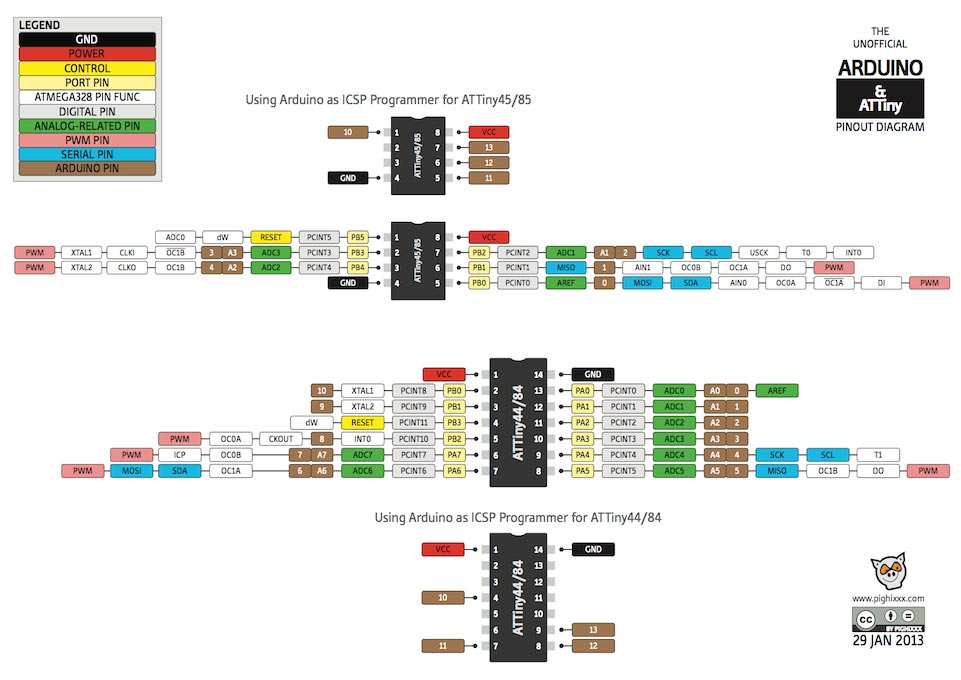
It was easy to find Attiny board 44 from data sheet and I’ve read it thoroughly to check which number of pins are connected to other boards and It came to me that finding ‘GND’ and ‘VCC’ is very important when looking at certain components.
 |
 |
ATTINY DATASHEET |
LOOKING AT PINOUT |
 |
 |
NO4. HELLO BOARD |
ARDUINO CODE(HELLO.LED) |
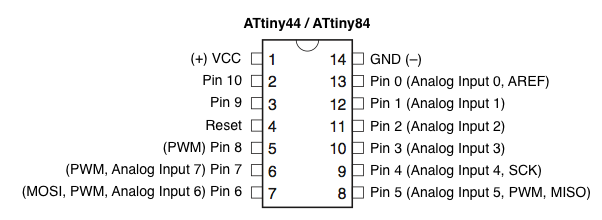
pin-out arrangement for Attiny44
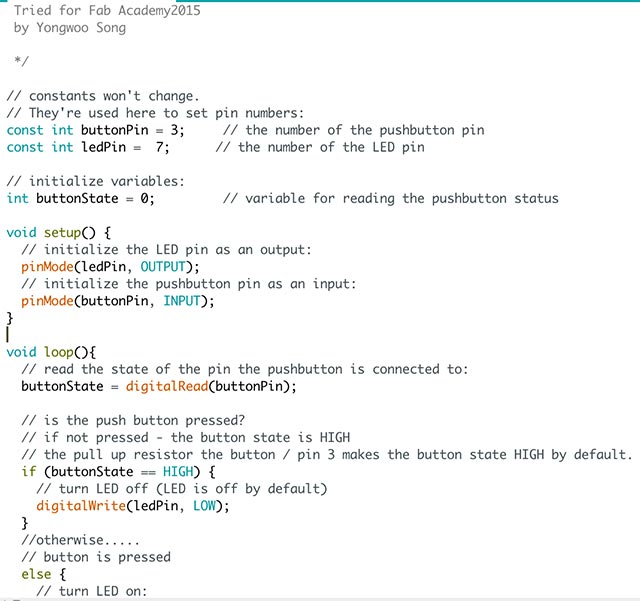
Looking at the DATASHEET and the eagle schematic file I read the datasheet of my analog input(LED) is connected to pin7. Which means in Arduino coding I have to set const of ledpin=7 to match the pin. I was told many times from my instructor that I should read datasheet many times as possible.
const int buttonPin = 3; (analog inpu
const in ledPin = 7;
Learning from failure
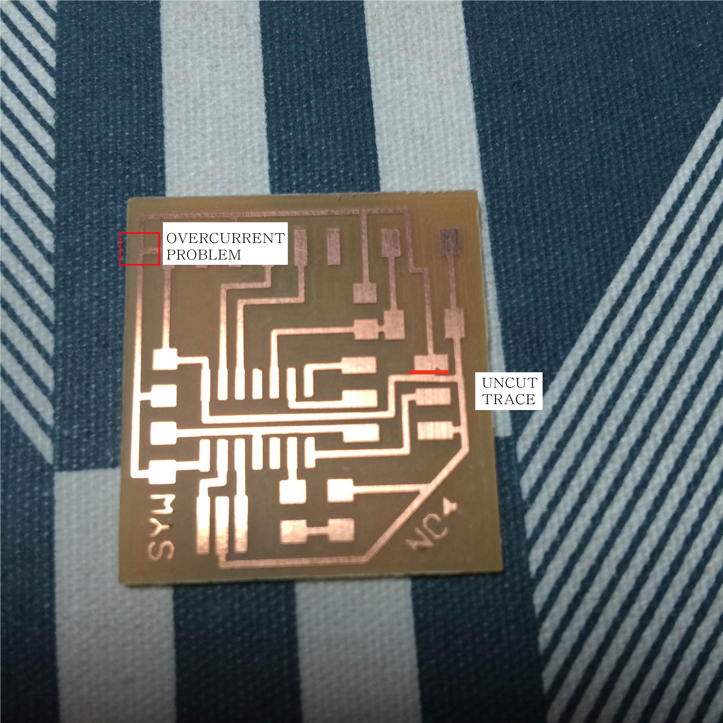
As i forgot to look more closely at the fab modules i found some un-cut traces and i manually with the cutter cut the traces to prevent bridges. There was a problem with my electronic design which i didn’t care for sure, which was there was a line which made a path directly from GND to VCC. Which could have a big mess to my board and set fire. When i connected the circuit with computer i could actually see the smoke and i knew that Macintosh automatically disable the circuit with overcurrent but Windows don’t !!! Learning from mistake again.
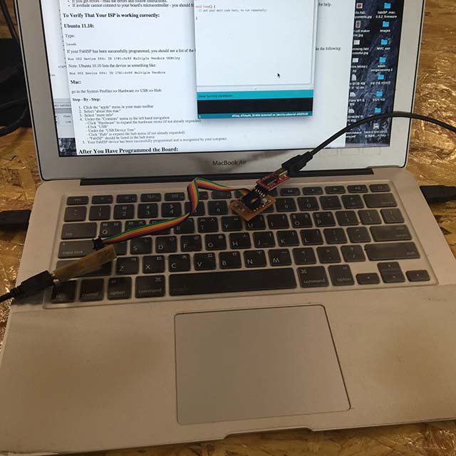
I’ve had a problem with programming the FabISP. FabISP is still giving me a lot of troubles and therefore i had to look again again and again.
I’ve checked again in my Mac OS to make sure the FabISP is successfully programmed and my computer recognizes as the USB( for Mac OS -> Go to ‘System preference’ -> Hardware)
If it is successfully programmed It normally catches the FabISP.
I’ve also checked with ubuntu and checked in terminal with command ‘lsusb’ to check if the FabISP is successfully connected.
I’ve done lots of trials to make ‘one’ successful FabISP. It was done my fifth trial and there were mistakes like using resistors that are not correct and other problems.
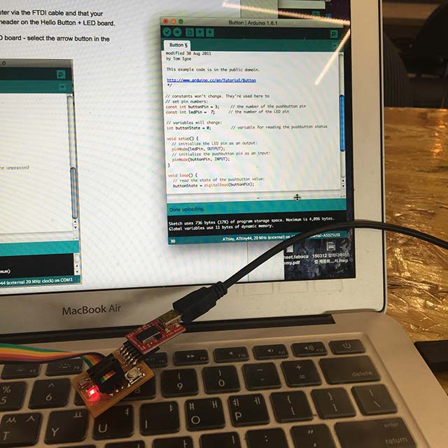
Programming with Arduino IDE
 |
 |
Blinking LED |
Connecting both boards |
By looking at the references sites ‘As220 Labs’ I could test my hello-board for testing the button when button is pressed, the led comes on to modify the board i’ve wanted to make it blink in faster speed by adding some code with delay(50); and switching the buttonState from ‘HIGH’ to ‘LOW’ constantly.
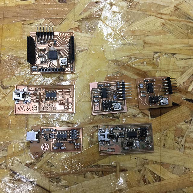
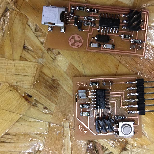
Current status of ‘SYW board’
 |
 |
CURRENT STATUS OF MY BOARDS |
SYW BOARD BLINK |
-
one FabKit v.0.2
-
two Hello.syw.board with components
-
three FabISP with only one working
Right now at the moment I’ve made 6 boards only 3 of them working and others for references and later-on reusable components. I’m always learning a lot from failures and I’ve been using lot of components and now I’m really trying to unsolder components to re-use it and save parts.
What I learned ....
Using FabISP to programme the board to tell what to do, read the data sheet and look at the available pinout to do something and understanding schematic of microcontroller. Doing the Arduino coding was not yet difficult since I had only one LED to control and one switch.Obviously the arduino coding is to set the variable tell what to do in void loop() { turn on, wait, turn off, wait // what i need to tell to the microcontroller }