11. Output devices
Add an output device to a microcontroller board you've designed and program it to do something
Board Trial
-
Try the board that is already designed and programme it
-
Re-design the board of my own design to do something // Stepper motor
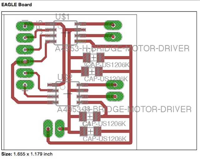
For this week, I wanted to try the bi-polar stepper motor circuit as to build axes control with the motors.
Sally Williams page says that another fab.lbr contains A4953 part and it’s necessary for my board. I looked at her electronic design configuration and it was exactly what i needed for my project. Controlling board with clockwise and anti-clockwise direction I’ll be able to control my axes in x, y axes as i intended to control.
 |
 |
On linux (Mac OS X) Terminal |
With etching problem chaning the board |
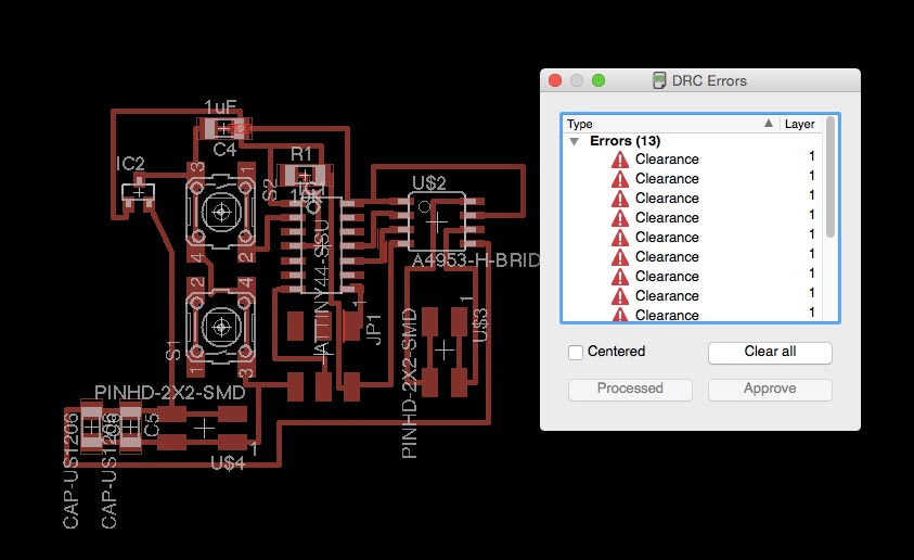
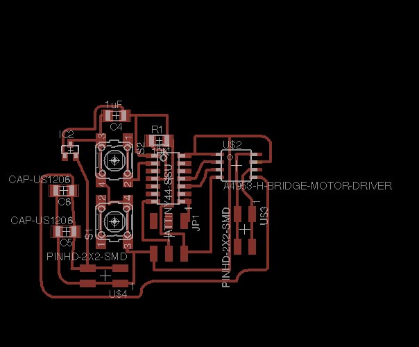
Now I’m always checking my design to be sure about clearance and less time doing self cutting traces after the milling.
 |
 |
On linux (Mac OS X) Terminal |
With etching problem chaning the board |
With the board adding 2 switches I wanted to try clockwise and anti-clockwise but with all finished artwork of PCB board I didn’t know that DC motor is difficult to control in the way that i intended. This happened with lack of knowledge of my electronic background.
-----------------------------
Under update
-----------------------------
Since my last misunderstanding between DC motors and stepping motors components alignment I’m down to the stepper motors
I wanted to use the FabKit (a.k.a Fabduino) and connect multiple output devices to do something that I intend to do. Therefore, It was important for me to do some trial with hello.stepper bipolar and DC motor for trying output device.
Before connecting I needed to programme my FabKit as usable and with ISP and hand-made connectors carefully see the position of RST and for me I first located RST and GND of two boards.
Just before, removing the components and redesigning the board I had to learn basic electronic components theory such as capacitors connected with IC controller and what IC controller does. For IC controller now I see the component as ‘smart’,’multiple’ switches by which means It’s just a normal switch inside tells the power(or electric current) to flow in 0,1 directions.
BE CAUTIOUS
It was important to check the voltage to run stepper.motor as I’ve already seen a smoke when connected with my laptop. It was kind of a surprise since I knew there should be power cut inside laptop that prevents overcurrent for safe issue. It was therefore important to keep an eye on it and be ready to pull the pin out to save my board.
 |
 |
On linux (Mac OS X) Terminal |
With etching problem chaning the board |
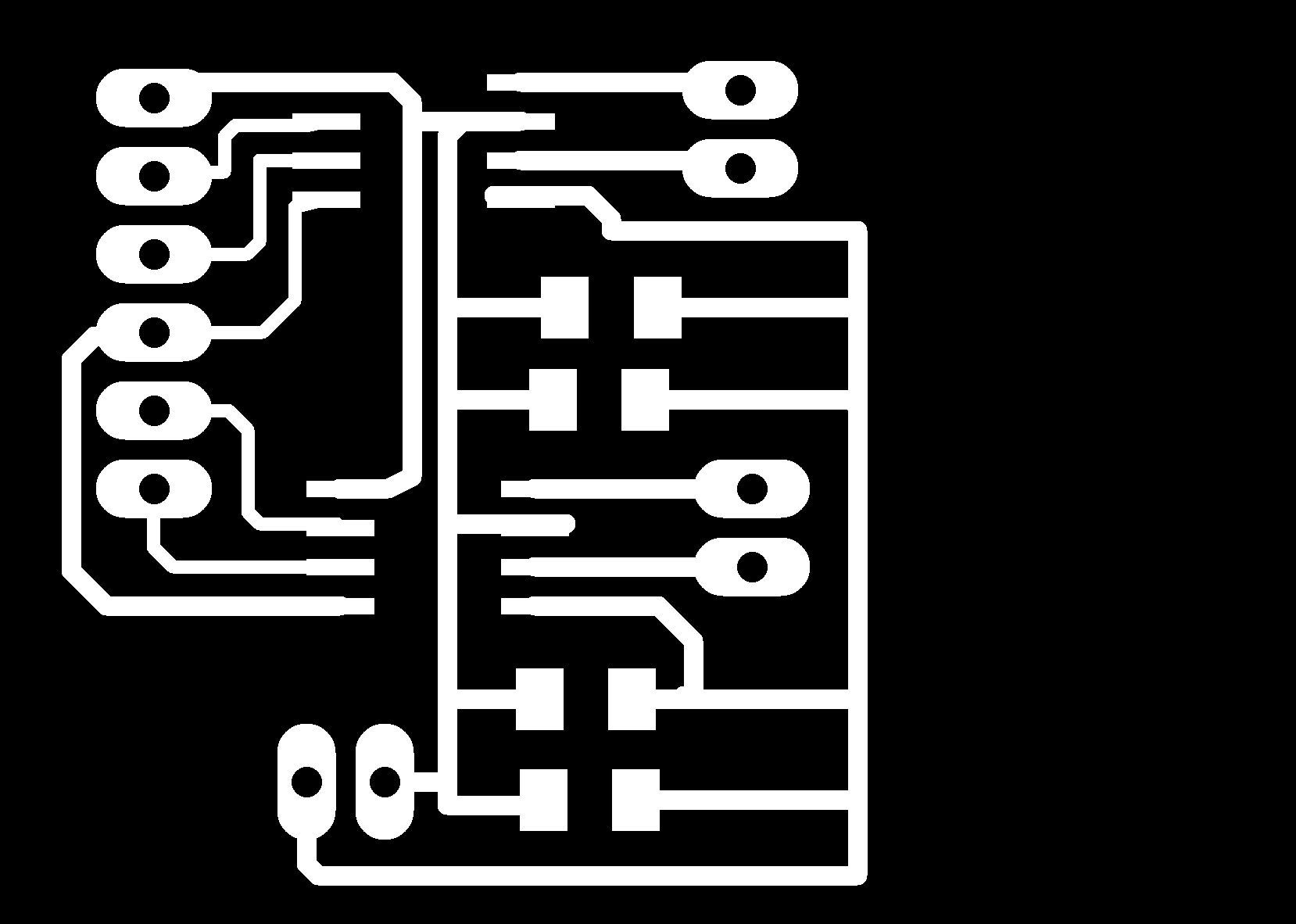
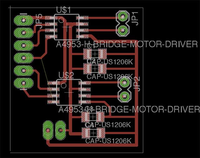
First, I checked on a hello.stepper bipolar board design to know which components can be removed or can be stayed to get the board working
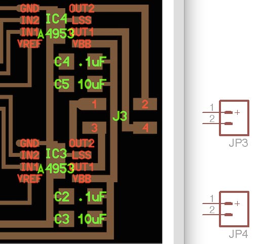
I renamed the JP3 and JP4 file to head it to the bottom IC so named the wires as ‘OUT3’ & ‘OUT4’
By finishing the design of my stepper.motor I found a serious problem with sharing voltage between IC1 and IC2, with current design above the above IC1 gets the power from FabDuino which is around 5V and the bottom IC2 gets the power from outer supply of 12V which could kill the motor from one of them. Additional problem with the board is that the wire that is connected to the power GND is too narrow and by far which I’ve asked from the professor or my other colleague for 1mm it is capable of letting 1A of current.
One more thing that i switched for good connections was to change the 2 pin headers that is same with other 6 Pin and GND VCC header which I already have done with making FabDuino.
Therefore, with research and help from the instructor I routed my decision to not add components and share the same voltage by correcting the IN1 of both motors.
This is the board with shared voltage in both IC ‘s and will be used as a controller of my two stepper motors to do CORE XY movement. I’ll be making another board named for ‘STEPPER2’ and connect with FabDuino .
 |
 |
On linux (Mac OS X) Terminal |
With etching problem chaning the board |
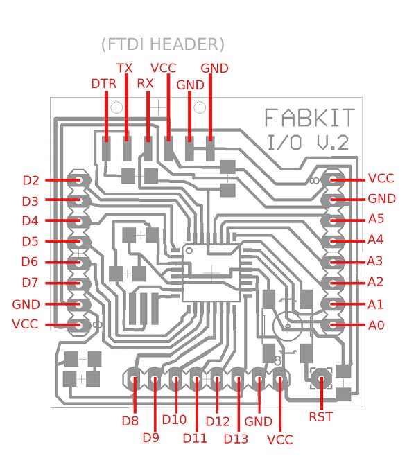
As I mentioned before, I looked up the FabKit information and checked for FTDI cable layout and Digital pin position and for me I want to use D2,D3 …. D7 for stepper board. I
I looked again for tutorial and got reminder again that the Fabduino gets the power supply of 5V from FTDI cable for powering the board and programme it with Arduino IDE.
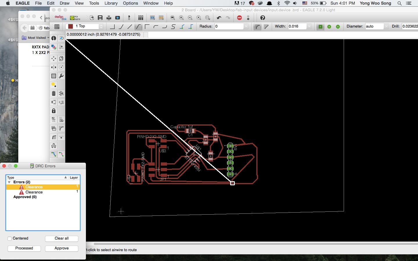
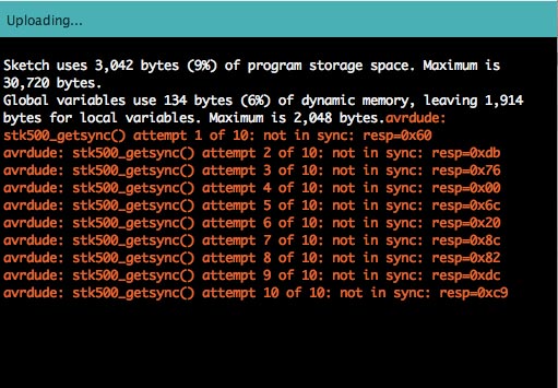
For programming the board I need a configuration in the setting of boards.txt file which is the shown setting of an Arduino IDE.
This kind of error happens as far as I’ve found with googling is bad connection that Arduino is not connecting with software
Test the stepper motor
 |
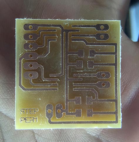 |
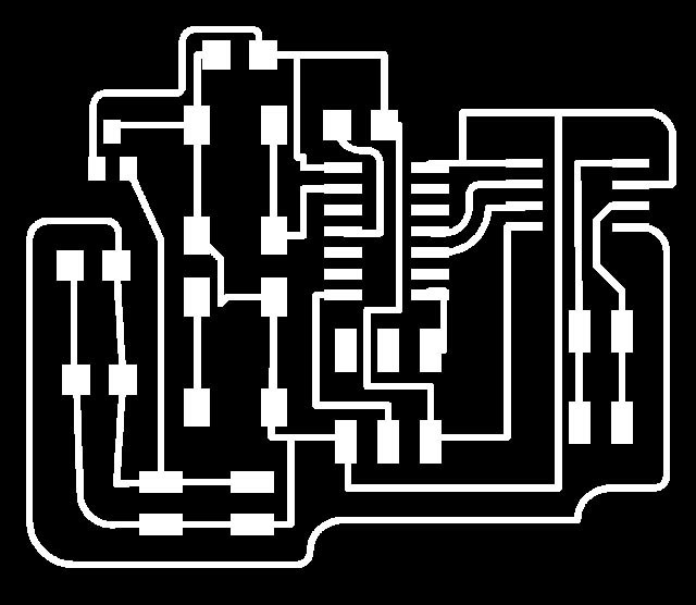
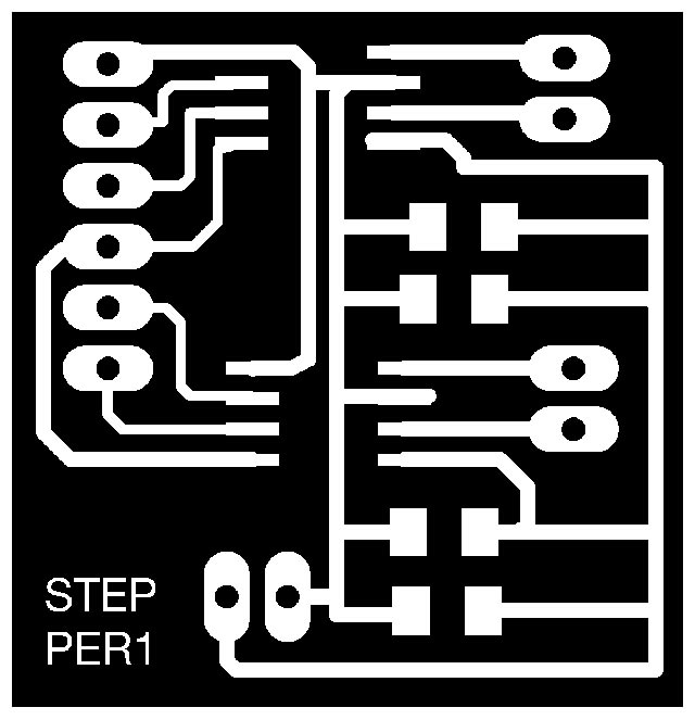
PNG FILE OF STEPPER |
STEPPER1&2 MILLED |
 |
|
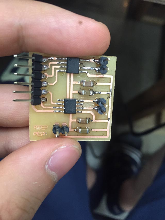
COMPONENTS MOUNTED |
(movie) Trying the motor moving with one stepper programmed, trying with other sets of digital pinouts
// I had two problem which the power supply not making the voltage that I want, which i thought at first was the breakdown of the power supply. The stepper motor was not making the continuous turn that I was intending and making strange ‘squeaky’ sound which is definitely that something is going wrong.
I fixed first problem with power supply by correcting the knob with the current and giving it a be cautious about rising the voltage.
Second problem was fixed by checking the stepper board I’ve made and I could see the data pin which connects with the stepper motor hasn’t been soldered properly so I made sure the solder gets under the pin with more than enough solder to make sure I don’t lose connection.
Then I changed the motor pins’ value to D2, D3, D5, D6, D7 and removed the sentence that wasn’t necessary for testing.
int motor pin = 2; // D2 connect with PA0
int motor pin = 3; // D3 connect with PA1
int motor pin = 5;// D5 connect with PA2
int motor pin = 6;// D6 connect with PA3
int motor pin = 7;// D7 connect with PA4
# I’m still not sure why my colleague encouraged me to leave out the fourth pin of FabKit therefore I still need to find out what’s the problem is with using the D4 pin.
Just as i finished the testing with first stepper board I made exactly the same the second board to make additional connection to the FabKit. this time I used the pinout for D8, D9, D11, D12, D13 for the second stepper motor. Programming the board was to connect the FTDI and get the power from the computer and additional 12V from power.
The stepper motor now moves with continuous and with steady pace.
I have to make sure that all of my digital pin is working correctly and my stepper board and FabKit is working at the same time.
With stepper motor smoothly working as i intended I check the Amperage by giving some reverse force to check how much current is needed for one motor and as my power supply was between 0.7 ~ 0.5 A I assume for my final project i need at least 2A of power. It's finally done and now I can use it on my final project.