6. Electronics design
Re-draw the echo hello-board, add (at least) a button and LED
Check the design rules, and make it extra credit : simulate its operation
First, i installed eagle followed by the link from Fab Academy. Here are the menus where i could check my libraries that are needed for this week’s assignment.
 |
 |
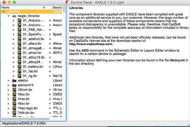
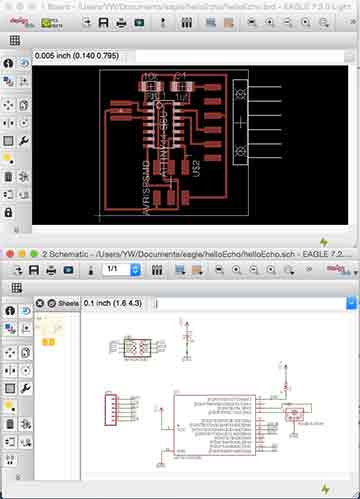
Loading the Eagle library |
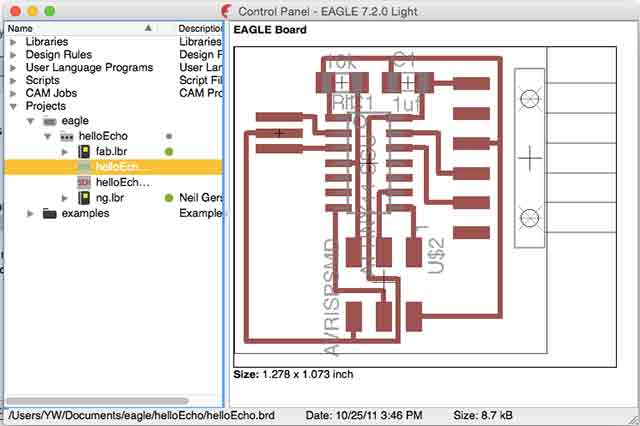
Loading Helle.Echo board |
Menus where i could check my libraries that are needed for this week’s assignment are shown below. Loading the library and unzipped at applications/Eagle 7-2.0/lbr and from the file menu i could check the library folders. This week i worked with helloworld.isp board and with the board tried to put 2 resistors and LED. Checking both schematic view and board view to understand the concept of circuit.
 |
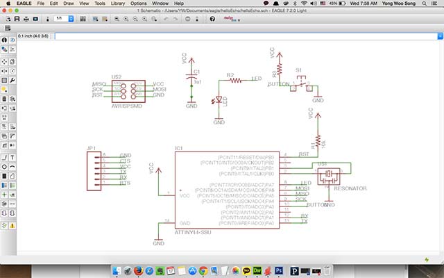 |
Schematic and Design view |
Schematic view of Hello.Echo |
 |
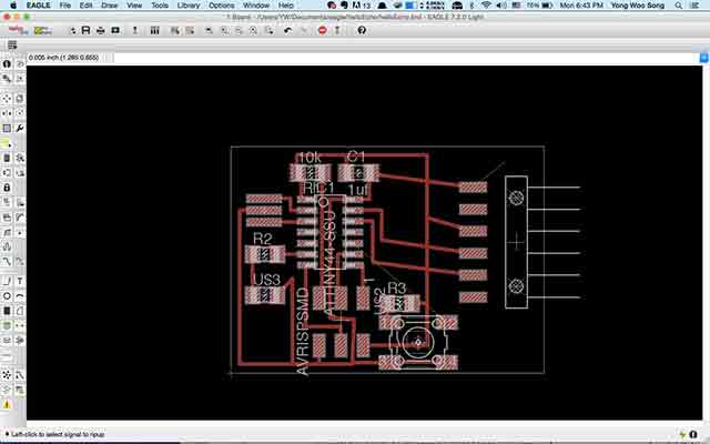 |
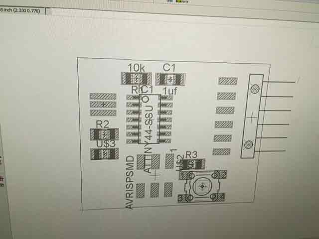
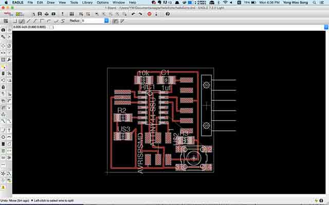
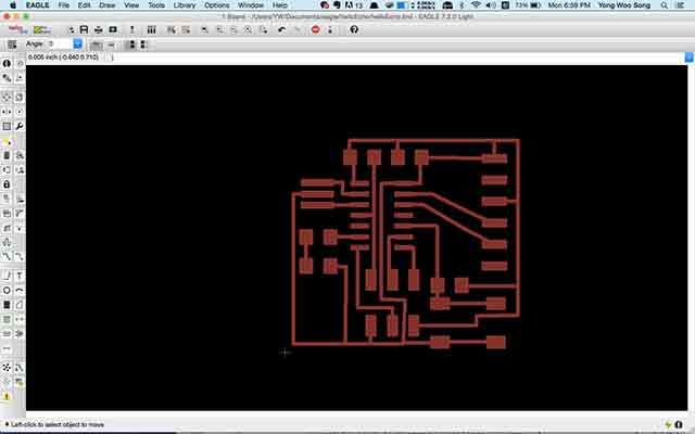
Design view of first Hello.Echo board |
Moving FTDI headers in design view |
 |
 |
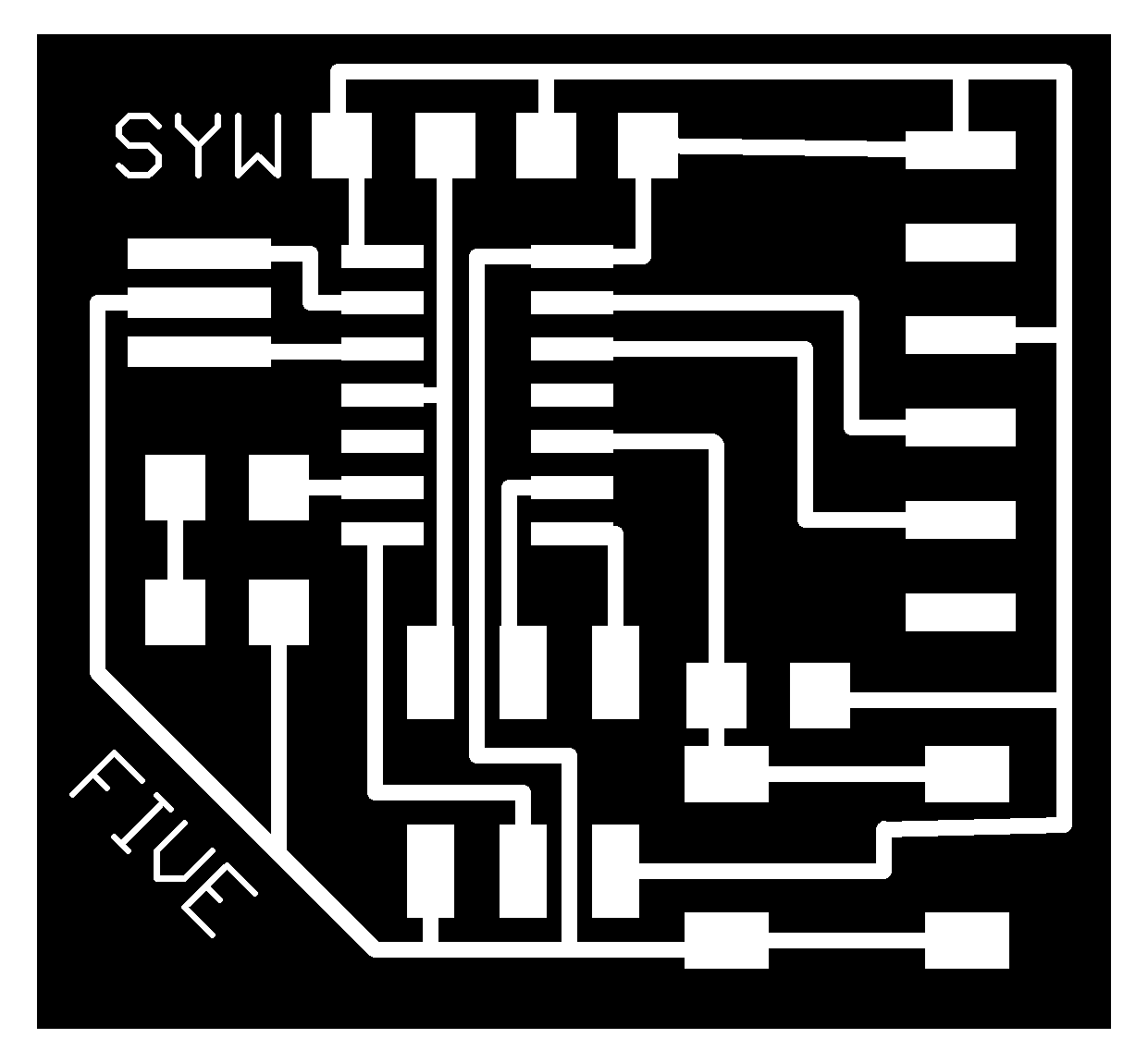
TOP LAYERSHOWN |
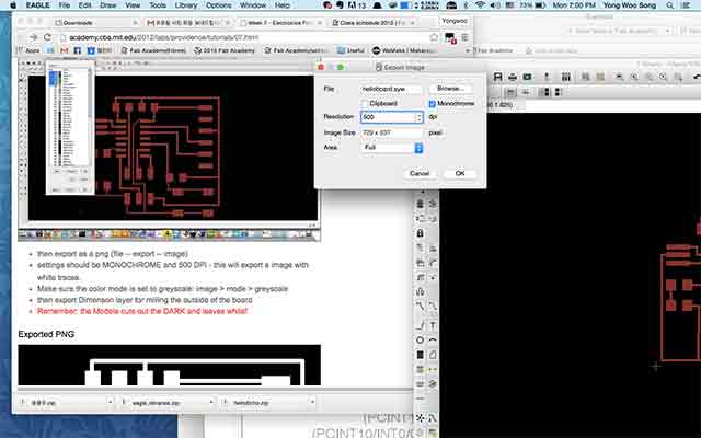
EXPORTING THE PNG |
It’s now ready to be exported to PNG file with all the layer for the other components view are gone.
To remove the components, click the view button and set for ‘monochrome’ and 500 dpi at least. For my board i wanted to be more precise so i changed the setting to 1000 dpi. I’ve countered problem with saving exporting image file with ‘out of memory’ error which I fixed with changing the direction where the files are saved. When the setting is defaulted in EAGLE programme folder this kind of error will happen.
 |
|
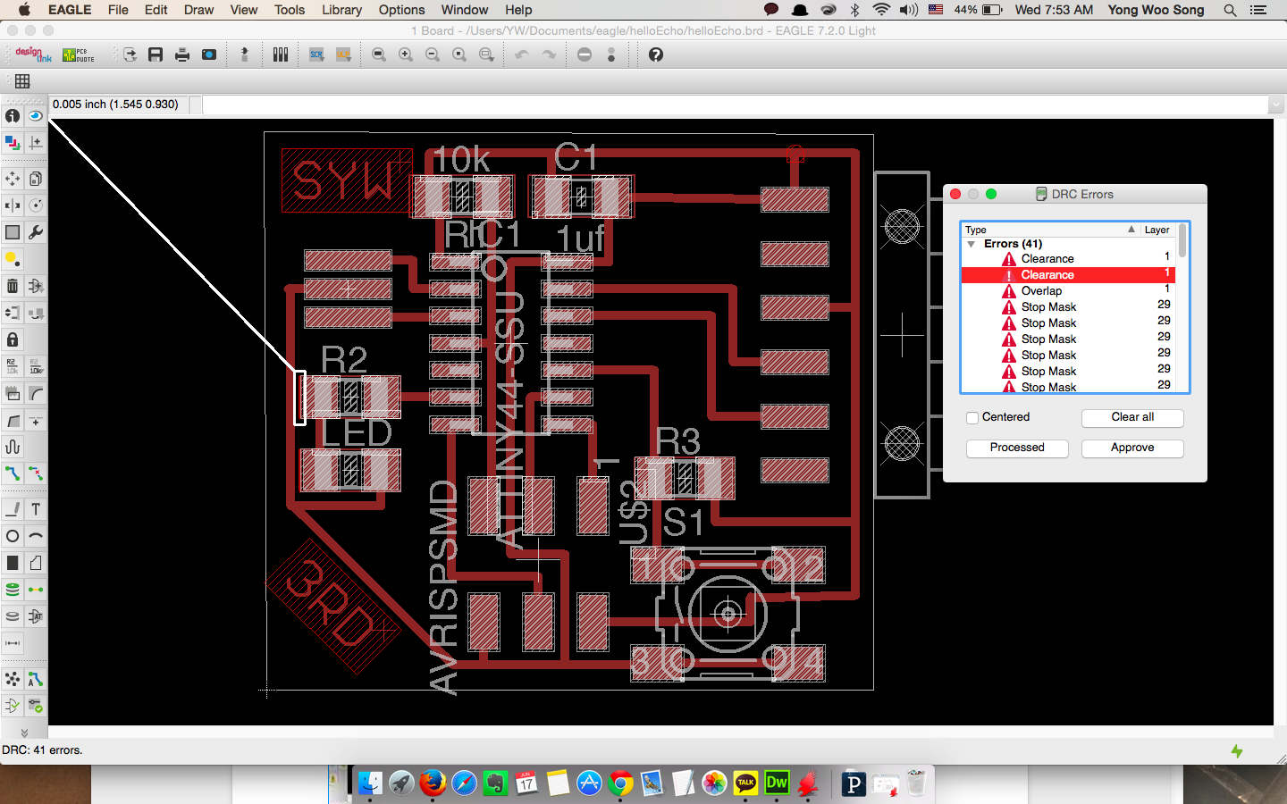
CHECKING CLEARANCE(DESIGN CHECK RULES) |
 |
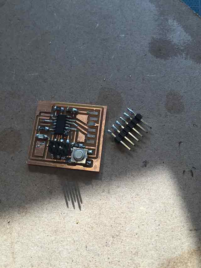 |
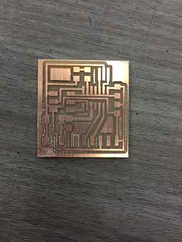
NO5 HELLOBOARD |
BROKEN FTDI HEADER |
 |
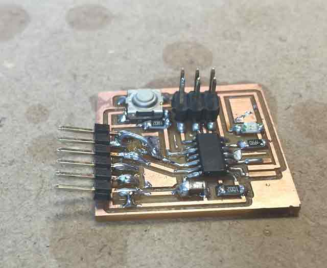 |
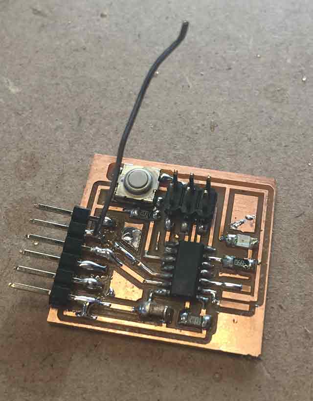
SOLDER FOR JUMPING |
FIRST TRY OF FIXING THE BOARD |