Assignment
design, make, and document a press-fit construction kit
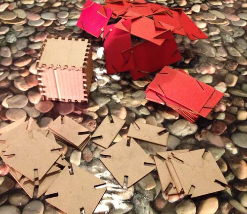
For my first laser cutting experience, I wanted to experiment with several types of materials, so I began with three little projects.
First of all, I build a box using 3 millimeters thick cardboard using this tutorial: Advanced - Press Fit Box.
For the second project I tried to make a Slide-Together Geometric Constructions following George Hart theories : Slide-Together” Geometric Paper Constructions.
I did not success because I choosed a very thick material than does not bend, but it breaks (1,8 mm thick pass partout).
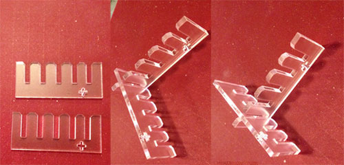
Finally I made some Slide-Together Structures with a rigid material (2,5 mm thick DMF), like the ones from Rinus Roelofs: Slide-Together Structures.
After that I was confident enough with the software (Inkscape and LaserCut5.3) and the hardware (GoldenSign GS1280 and GS9060 Laser Machines) to begin the week assignment.
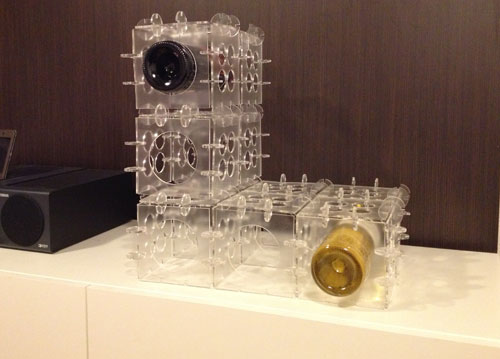
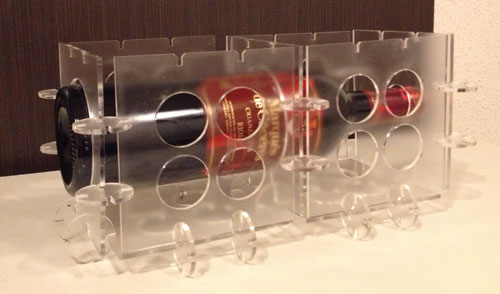
For my week assignment I have make a wine rack in 3 mm tick methacrylate.
I made the design of the pieces with Inkscape, export them as DXF files, and finally I import then into LaserCut 5.3 to send then to the Laser machine. In the end I have this
I began drawing the different pieces in Inkscape. There are two things than I have learned the hard way than can save you some time.
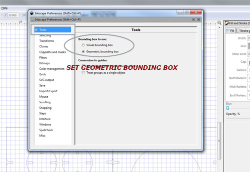
In Inkscape, positions and dimensions are reference to the bounding box. You can choose between two definitions for the bounding box, the visual or the geometric in the Tools section of the Inkscape Preferences dialog File/Inkscape Preferences.
The Visual bounding box includes the stroke width, if the stroke is visible. For example, a square 100 pixels to one side (between corner nodes) will have a width of 102 pixels if the stroke width is 2 pixels.
The Geometric bounding box mode uses only the nodes to determine the bounding box.
It will be easier to create tiled clones without worrying about the Stroke width, so select the Geometric bounding box in the Tools section of the Inkscape Preferences dialog.
Secondly, when you make tiled clones Inkscape make one clone on top of the original object. I recommend you to delete it for two reasons.
It is necessary to modify the original object if the clones are also to be modified. If you have a clon on top the original you can not do it. You need to raise it above the clon before you can modified it, you can do it by clicking on any of the clones and using Edit/Clone/Select Original, then bring it to the top by using Object/Raise on top on the menu bar.
Also if you have a clone on top the original one, when you send the file to the laser machine the laser is going to double cut on the same line, because one object is superimposed to the other one.
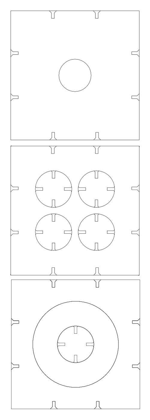
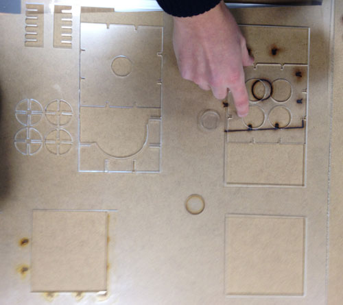
The desing have 3 different square pieces, one for the body of the bottle, one for the neck of the bottle and one for the laterals, top and botton and one circle piece for the unions.
The next step in the project is to select the laser settings for the material.
After cutting some squares, I choose: Speed 17, power 40, corner power 37.
After that, I measured the kerf created by the laser machine see this tutorial: Press-Fit Construction Tips.
And then, I tested the fit of various notches.
Then, I adjusted the notch width in the Inkscape files, I made the pattern using Edit/Clone/Create Tiled Clones and export then as DXF. Finally, I imported then into LaserCut 5.3 to send then to the Laser machine.
There are three things to do before you send them to the Laser machine:
1.- To up or down the layers in relation to the order than the laser should cut all of them.
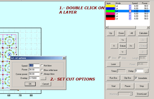
2.- Set the cut parameters.
You can set the same parameters to all the layers or different parameters to each one.
Double click on the color identification bar of the layer, and then a dialog box pops out as below
These are the definitions of each parameter:
Speed: operating speed of the laser head in cutting
Power: adjust the minimum (unit: %) of laser power in operating the layer.
Corner Power: adjust power of laser head when its speed is the minimum in the variable speed motion
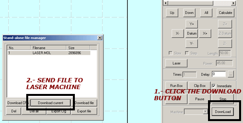
3.- Click Download data button, a dialog box appears as below.
Click Download current to download the current processing data to the laser machine.
Finally, before to start cutting we must adjust the focal distance, because the cut will
be not good if the focal distance is not accurate.
Then, press start and wait until the machine finish the work.
To finish, I just had to assemble it.
Final files:
frontal.svg
lateral.svg
back.svg
|