Fab Labs. Advanced made simple.
Local Solutions for local problems.
Posted by James Akumu | For Fab Academy
Echo Board Project
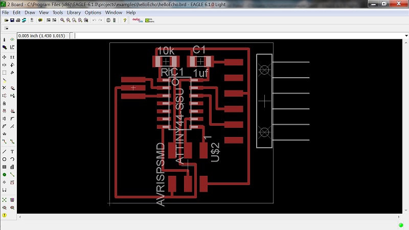
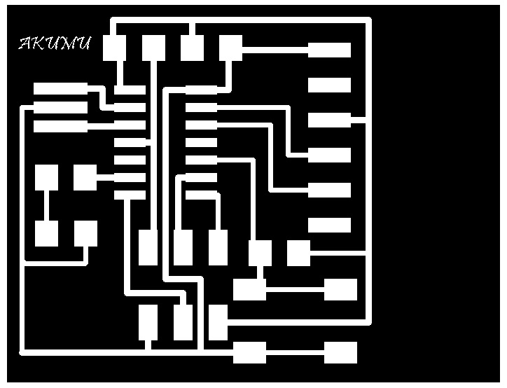
For the this project, we are to redraw the echo hello-world board above, using the CadSoft Eagle software, and add a button and LED, and make the new board.
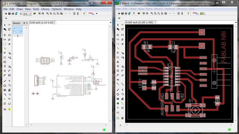
The first thing I had to do was to familarize myself with CadSoft Eagle software. I did this by going through the tutorials provided. I also found some good tutorials on youtube. Once I figured out the basics, I went on to download the sample echo board schematic and board (above).
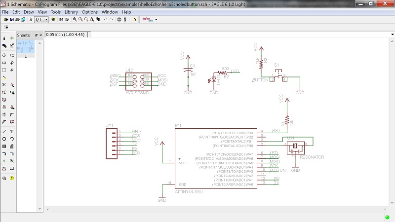
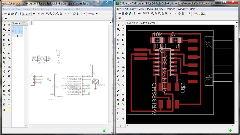
After downloading and installing the component library, I started adding the necessary components to the sample echo board schematic. I added a 10k Resistor; button (OMERON switch); grounds; VCC (connection to power); LED (Light Emitting Diode); Resistor (499 ohms).
After adding all the necessary components to the schematic, I connected them, and then routed the traces on the board.
After routing all the traces, I exported the board design in monochrome and 500DPI, to be used with the Modela. I did some minor editing using GIMP.
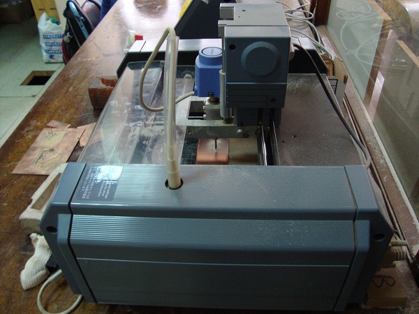
With all the editing done, I set the number of contours to -1 and sent the design to the machine for milling.
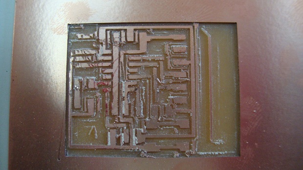
This first board did not mill properly. Some of the traces were completely milled off. Maybe I did not set the Z height of the end mill properly. Or maybe the Modela was shaking too much as a result of people walking around the Modela while it was milling. I will mill another board.
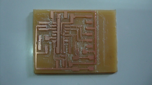
The second board came out better than the first, but some traces were milled out again. I will try and fix the traces with solder, before milling-out another board. I might have to go back to the design to make the traces being milled-out a little thicker.
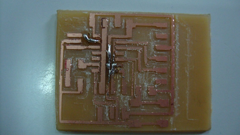
Fixing the traces did not work. The spaces were too narrow to work in. I will have to mill another board.
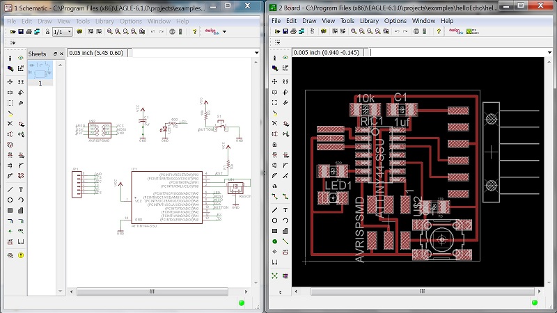
Before milling-out another board, I decided to change the design of the echo board to have more space in-between the traces, and not be so congested. This should give the bit enough room to mill, without milling the traces. I moved the components around and re-routed them.
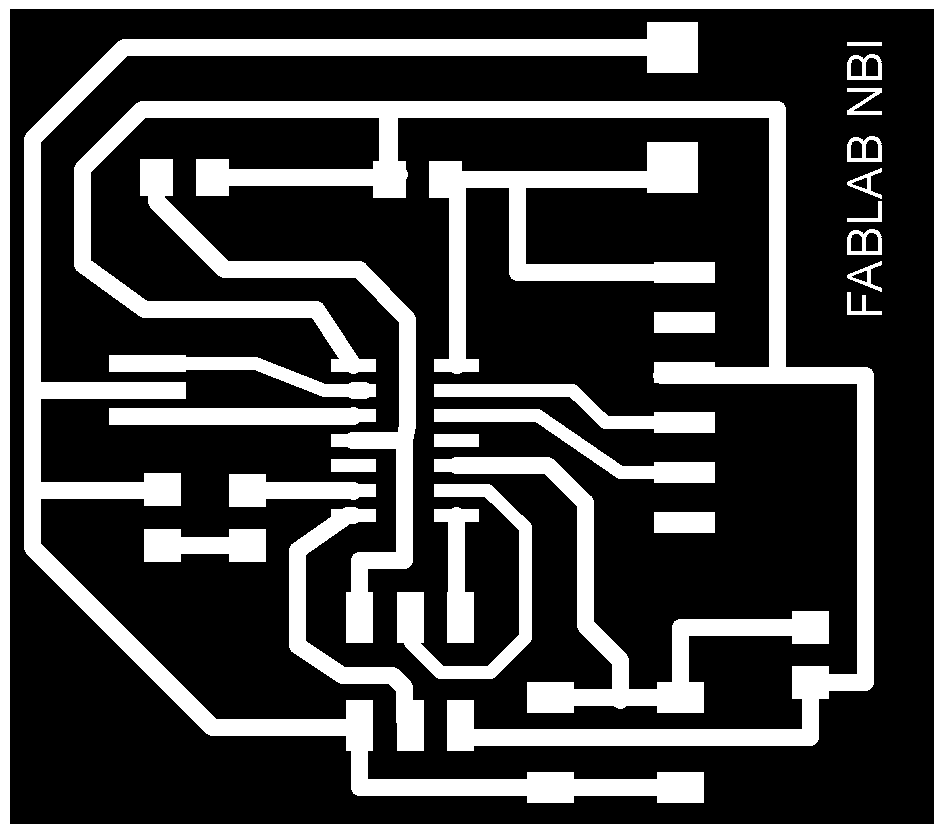
I then exported the new board design, edited it, and sent it to the machine for milling.
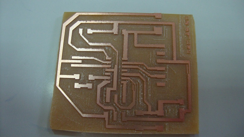
Success!! Finally, a decent board is milled out.
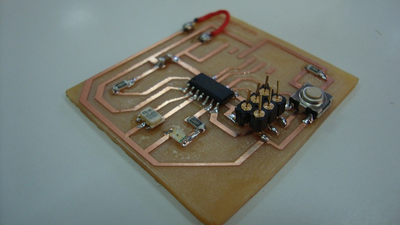
Stuffing the board was quick and easy. Onto programming the board.