Week 04 — Group Assignment
Embedded Programming
This group assignment compares available embedded architectures, programming environments, toolchains, and development workflows. It also includes practical tests based on serial monitor interaction and local UART communication between boards.
Personal Contributions
| Name | University | Activities carried out |
|---|---|---|
| Rodrigo Guamán | Universidad de Cuenca |
|
| Jenny Rojas | Universidad de Cuenca |
|
| Diego Zhindón | Universidad Politécnica Salesiana |
|
1. Checklist
- ✅ Identified the embedded platforms used by the group
- ✅ Compared toolchains and development workflows
- ✅ Documented embedded architectures used in the lab
- ✅ Compared programming environments and language options
- ✅ Documented coding foundations relevant to Arduino-style development
- ✅ Demonstrated serial monitor interaction with a real board
- ✅ Prepared and documented local board-to-board UART communication
- ✅ Added common errors, logic-level considerations, and references to individual pages
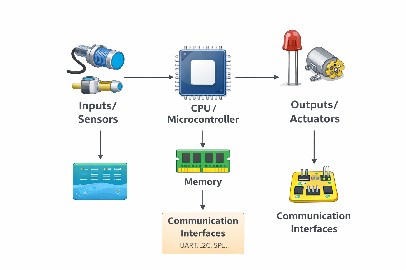
2. Embedded Systems Overview
An embedded system is a computing system designed to perform a specific task inside a larger product or technical process. Unlike a general-purpose computer, an embedded platform is optimized for control, sensing, communication, and low-resource operation. These systems are common in automation, robotics, smart products, sensor nodes, industrial interfaces, and IoT devices.
| Concept | Embedded System | General-Purpose Computer |
|---|---|---|
| Main purpose | Specific dedicated task | Multiple user-oriented tasks |
| Resources | Limited memory and processing power | Higher memory and processing capacity |
| Power consumption | Usually lower | Usually higher |
| Interfaces | GPIO, UART, I2C, SPI, PWM | USB, HDMI, network stack, OS-level interfaces |
| Typical use | Control, sensing, communication, automation | Office work, media, multitasking, software development |
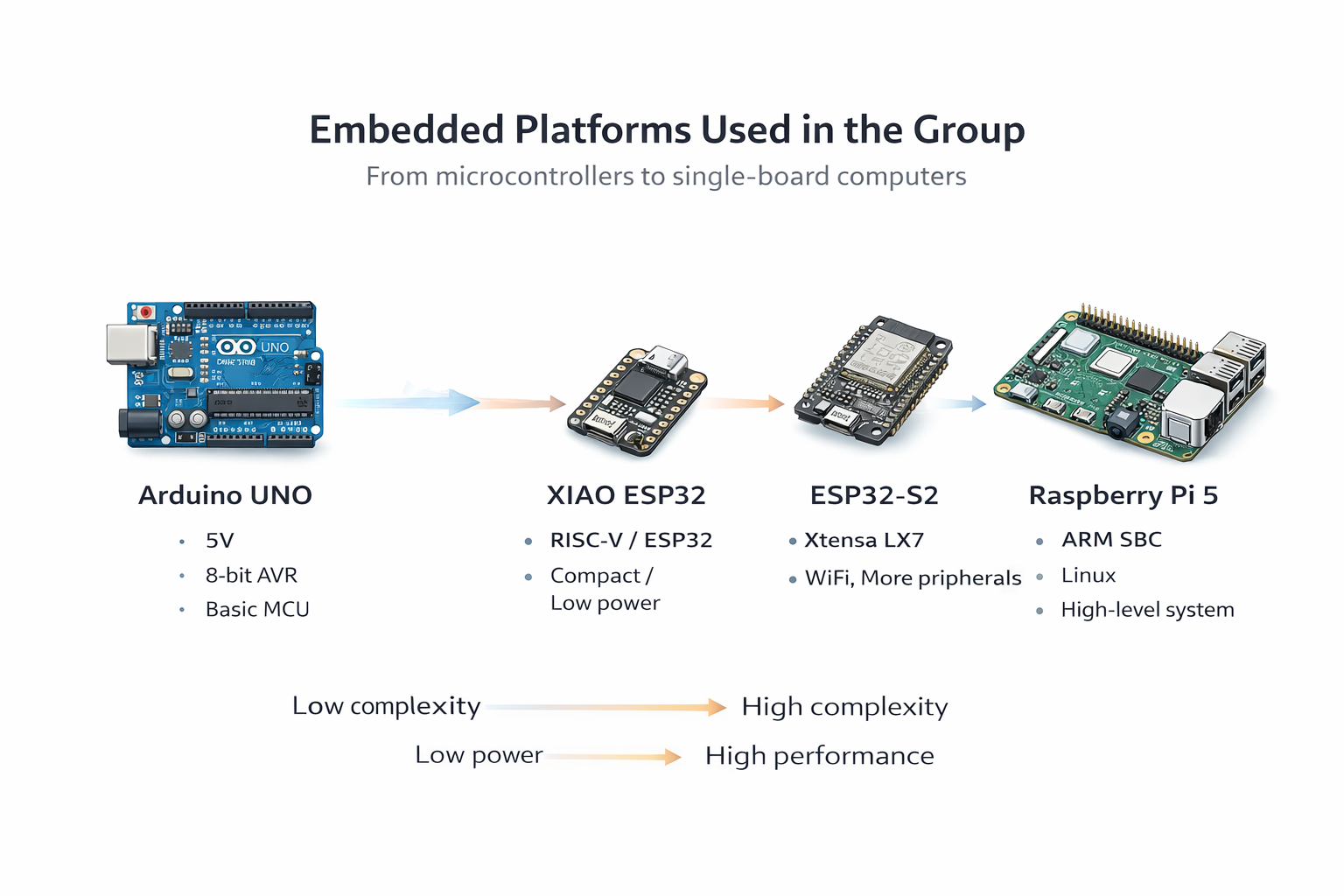
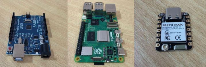
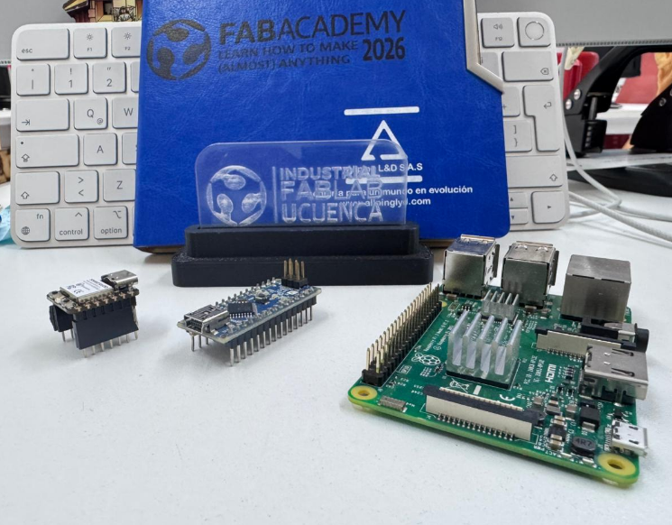
3. Platforms Used by the Group
Across the three individual assignments, the group documented a range of relevant platforms: classic AVR boards, ESP32-based boards, compact XIAO modules, and a Linux-based single-board computer. This variety makes it possible to compare microcontroller families, architecture differences, and development workflows.
| Board | Architecture | Type | Main Logic Level | Programming Environment |
|---|---|---|---|---|
| Arduino UNO | AVR ATmega328P | Microcontroller board | 5V | Arduino IDE |
| Arduino Nano | AVR ATmega328P | Microcontroller board | 5V | Arduino IDE |
| XIAO ESP32-C6 | ESP32-C6 family | Compact microcontroller board | 3.3V | Arduino IDE |
| XIAO ESP32-C3 | RISC-V | Compact microcontroller board | 3.3V | Arduino IDE |
| ESP32-S2 | Xtensa LX7 | Microcontroller board | 3.3V | Arduino IDE / ESP-IDF |
| Raspberry Pi 5 | ARM-based SBC | Single-board computer | 3.3V GPIO | Python / Linux environment |
4. Toolchains Comparison
One of the main goals of this week is to compare toolchains and development workflows. Even when several boards can be programmed from the Arduino IDE, their board packages, architecture-specific cores, upload behavior, and capabilities are not the same.
| Platform | Toolchain / Core | IDE / Environment | Main Language | Upload Method | Difficulty |
|---|---|---|---|---|---|
| Arduino UNO | AVR core | Arduino IDE | C/C++ | USB | Low |
| Arduino Nano | AVR core | Arduino IDE | C/C++ | USB | Low |
| XIAO ESP32-C6 | ESP32 board package | Arduino IDE | C/C++ | USB | Low to medium |
| XIAO ESP32-C3 | ESP32 board package | Arduino IDE | C/C++ | USB | Low to medium |
| ESP32-S2 | ESP32 board package / ESP-IDF | Arduino IDE / ESP-IDF | C/C++ | USB | Medium |
| Raspberry Pi 5 | Linux + Python environment | Terminal / editor / Python | Python | Command execution | Medium |
The same IDE does not mean the same internal architecture. A board may share Arduino-style code structure while relying on a completely different core, logic level, upload method, and peripheral behavior.
5. Development Workflows
The workflow changes depending on the board family. Some boards are very direct to use, while others require installing board packages, selecting the correct programmer or serial port, or even running code from a Linux terminal instead of uploading firmware in the usual Arduino sense.
| Stage | Arduino UNO / Nano | XIAO / ESP32 Boards | Raspberry Pi 5 |
|---|---|---|---|
| Install environment | Arduino IDE + AVR boards | Arduino IDE + ESP32 package | Python in Raspberry Pi OS |
| Select board | Direct board selection | Requires correct ESP32 family board selection | Not a traditional board upload flow |
| Select port | USB serial port | USB serial port | Local or remote terminal access |
| Compile / prepare | Compile sketch | Compile sketch with correct package | Save Python script |
| Upload / run | Upload directly | Upload directly | Run with Python interpreter |
| Debugging | Serial Monitor | Serial Monitor | Terminal output / runtime output |
6. Practical Tests
6.0 Communication Pins Reference
Before running the practical tests, it is useful to identify the communication-related pins on both boards. This is especially important for UART tests and for understanding where TX, RX, ground, and serial-capable pins are located.
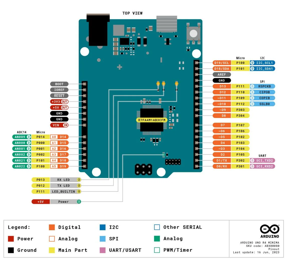
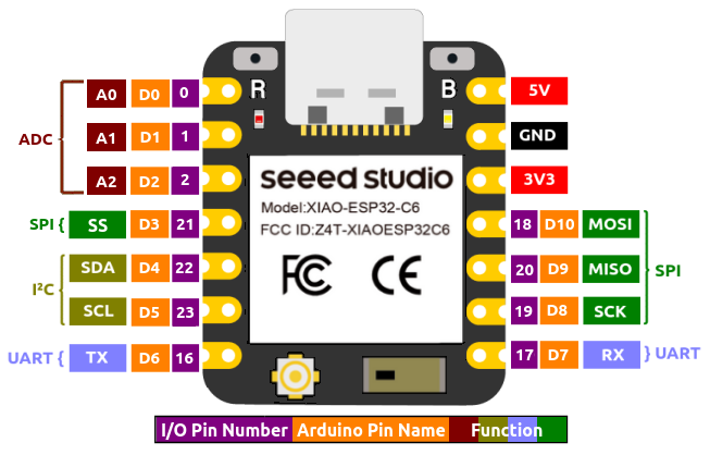
| Function | Arduino UNO | XIAO | Use in This Group Assignment |
|---|---|---|---|
| TX | D1 | UART TX pin | Serial data transmission |
| RX | D0 | UART RX pin | Serial data reception |
| GND | GND | GND | Common electrical reference |
| LED output pin | User-defined digital pin | User-defined digital pin | Output control in the tests |
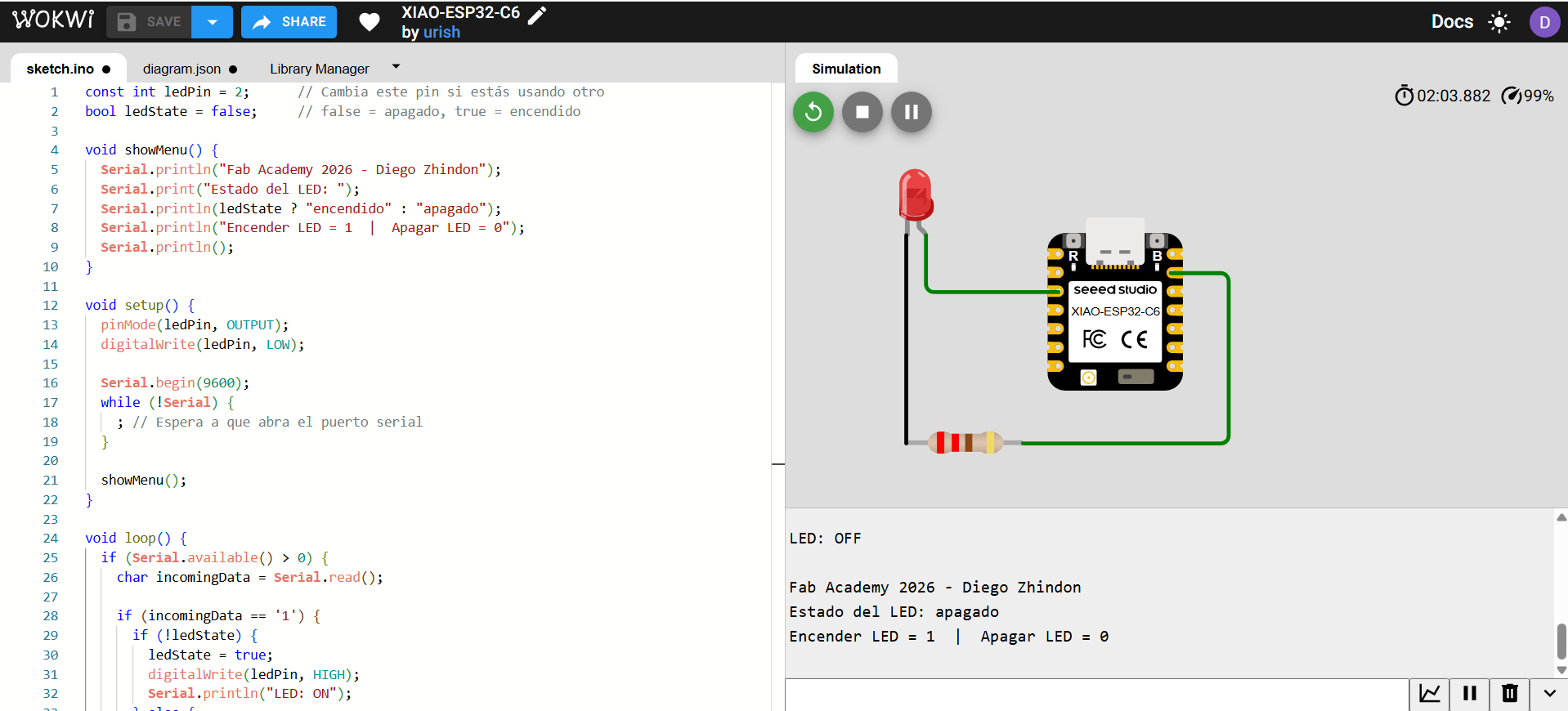
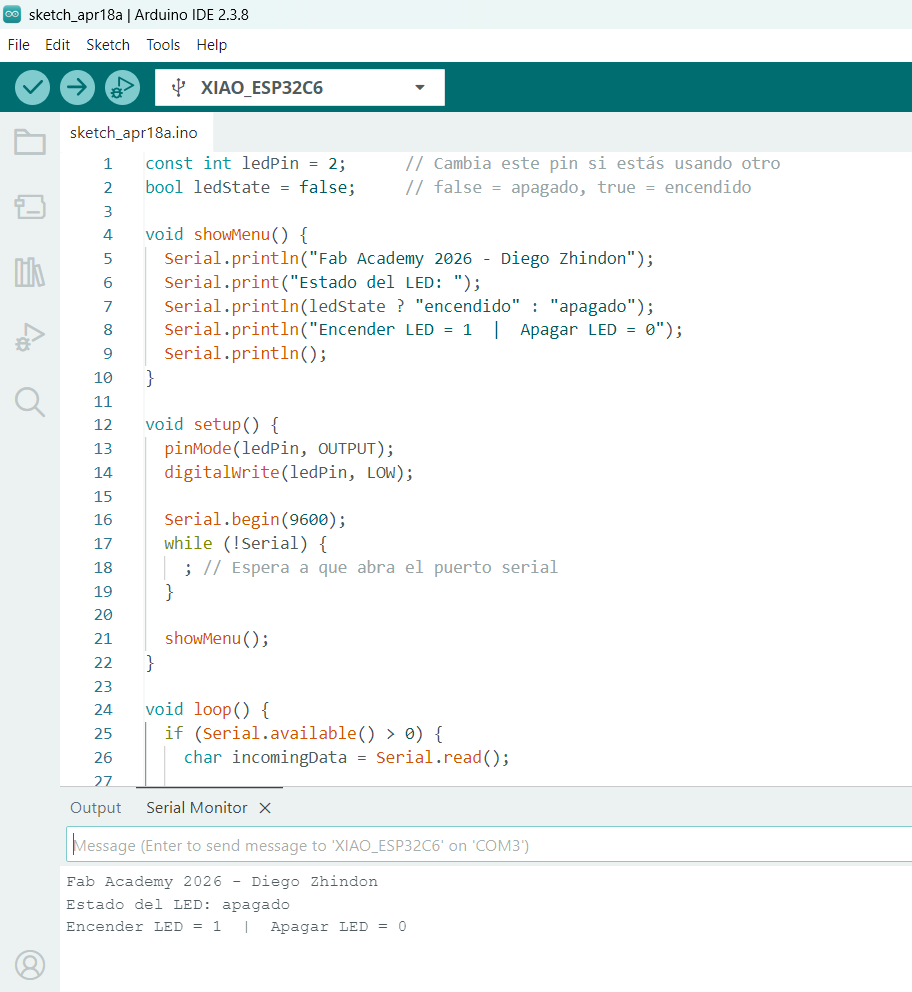
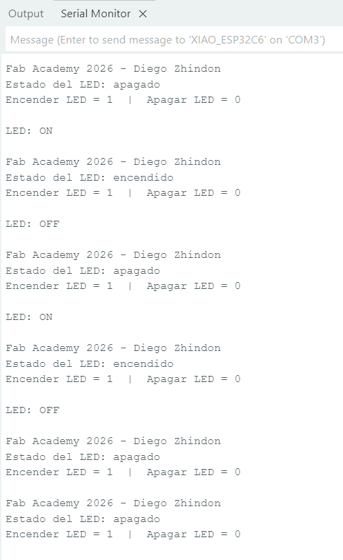
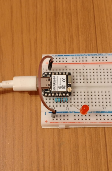
6.1 Practical Test 1 — Serial Monitor Controlled LED on XIAO
In this first test, the XIAO board receives data from the Arduino IDE Serial Monitor. Sending
1 turns an LED on, and sending 0 turns the LED off. This test is useful
because it combines code upload, serial communication, user interaction, and real hardware output
in a simple but meaningful workflow.
| Item | Value |
|---|---|
| Board | XIAO ESP32-C6 |
| IDE | Arduino IDE |
| Communication used | USB serial / Serial Monitor |
| Baud rate | 9600 |
| User input | Character 1 or 0 |
| Output | External LED ON/OFF |
| Pin Used | Purpose | Board |
|---|---|---|
| LED pin | Digital output for LED control | XIAO |
| GND | Return path for LED circuit | XIAO |
| USB serial | Communication with Arduino IDE Serial Monitor | XIAO |
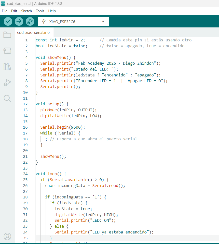
Code Used in XIAO
const int ledPin = 2;      // Cambia este pin si estás usando otro
        bool ledState = false;     // false = apagado, true = encendido

        void showMenu() {
          Serial.println("Fab Academy 2026 - Diego Zhindon");
          Serial.print("Estado del LED: ");
          Serial.println(ledState ? "encendido" : "apagado");
          Serial.println("Encender LED = 1  |  Apagar LED = 0");
          Serial.println();
        }

        void setup() {
          pinMode(ledPin, OUTPUT);
          digitalWrite(ledPin, LOW);

          Serial.begin(9600);
          while (!Serial) {
            ; // Espera a que abra el puerto serial
          }

          showMenu();
        }

        void loop() {
          if (Serial.available() > 0) {
            char incomingData = Serial.read();

            if (incomingData == '1') {
              if (!ledState) {
                ledState = true;
                digitalWrite(ledPin, HIGH);
                Serial.println("LED: ON");
              } else {
                Serial.println("LED ya estaba encendido");
              }
              Serial.println();
              showMenu();
            }
            else if (incomingData == '0') {
              if (ledState) {
                ledState = false;
                digitalWrite(ledPin, LOW);
                Serial.println("LED: OFF");
              } else {
                Serial.println("LED ya estaba apagado");
              }
              Serial.println();
              showMenu();
            }
          }
        }
This first test validated the complete basic workflow: simulation, code upload, serial interaction, and physical response in hardware. It also confirmed that the Serial Monitor can be used not only for debugging but also for direct control of an embedded output.
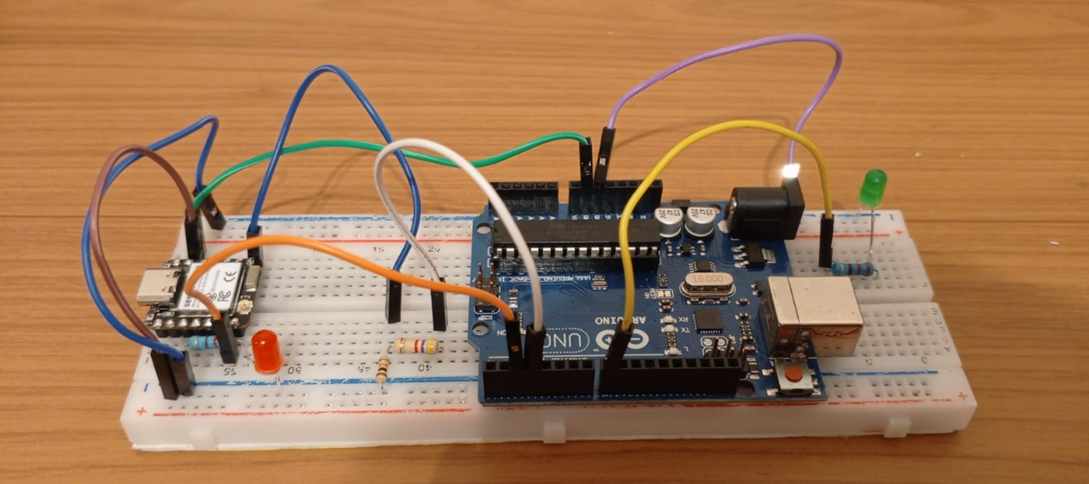
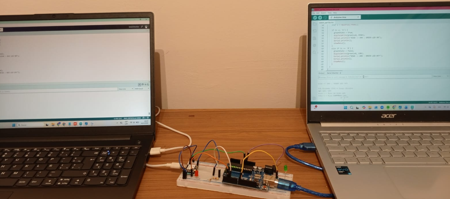
6.2 Practical Test 2 — UART Communication Between XIAO and Arduino UNO
In this second test, UART communication was established between two real boards. The experiment extended the previous serial interaction by sending data locally from one board to another. This test is especially relevant because it demonstrates not only code execution, but also signal compatibility, wiring strategy, baud-rate matching, and practical upload considerations when the hardware UART pins are in use.
| Connection | From | To | Purpose |
|---|---|---|---|
| UART line | XIAO TX | Arduino UNO RX | Data sent from XIAO to UNO |
| UART line | Arduino UNO TX | XIAO RX | Data sent from UNO to XIAO |
| Common reference | XIAO GND | Arduino UNO GND | Shared electrical reference for UART communication |
Important logic-level note: Arduino UNO works at 5V logic, while XIAO works at 3.3V logic. For this reason, the line from UNO TX to XIAO RX must be treated carefully, because the UNO can output a 5V HIGH signal and the XIAO input is designed for 3.3V logic. To reduce this voltage safely, a resistive voltage divider was used.
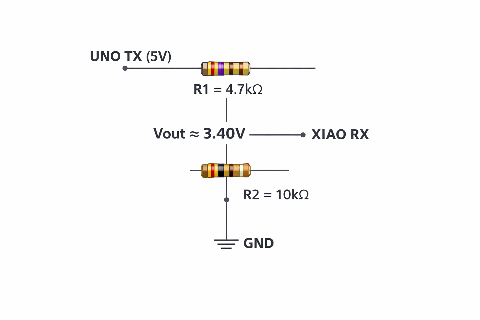
6.2.1 Voltage Divider Used for Safe UART Reception
To protect the XIAO RX input, the signal coming from the Arduino UNO TX pin was reduced using a voltage divider made with two resistors:
- R1 = 4.7kΩ — connected between UNO TX (Vin) and Vout
- R2 = 10kΩ — connected between Vout and GND
The output voltage of the divider is calculated with:
Vout = Vin × (R2 / (R1 + R2))
Vout = 5V × (10k / (4.7k + 10k))
Vout = 5V × (10 / 14.7)
Vout ≈ 5V × 0.6803
Vout ≈ 3.40V
This result safely reduces the 5V UART signal from the Arduino UNO to a value close to the 3.3V logic level used by the XIAO. This was a very important part of the test, because it prevented direct overvoltage on the XIAO RX input and demonstrated the application of basic electronics theory to real embedded communication.
6.2.2 Baud Rate and Serial Consistency
UART communication only works correctly if both devices use the same transmission speed. In our tests, both programs were configured to 9600 baud. If one board uses a different baud rate, the received bytes may appear corrupted, unreadable, or may not be interpreted correctly at all.
| Parameter | Value Used | Why It Matters |
|---|---|---|
| Baud rate | 9600 | Both boards must match the same transmission speed |
| Frame interpretation | Character-based | Commands such as '1' and '0' were interpreted reliably |
| Ground reference | Shared GND | Required for stable signal interpretation |
6.2.3 Important Upload Consideration When Using TX and RX
Important upload note: when the hardware UART pins TX and RX are connected between boards, uploading a new program can fail because those same pins are also used by the serial interface. In practice, the reliable workflow is:
- Disconnect the communication wires from TX and RX
- Upload the program to each board separately
- Reconnect TX, RX, and GND after the upload is complete
- Run the UART communication test again
This detail is important to document because it reflects a real laboratory issue that appears when the serial pins are shared between programming and runtime communication.
6.2.4 Visual Evidence of the UART Test
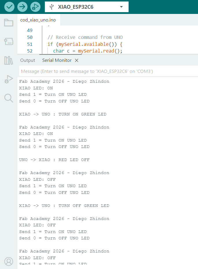
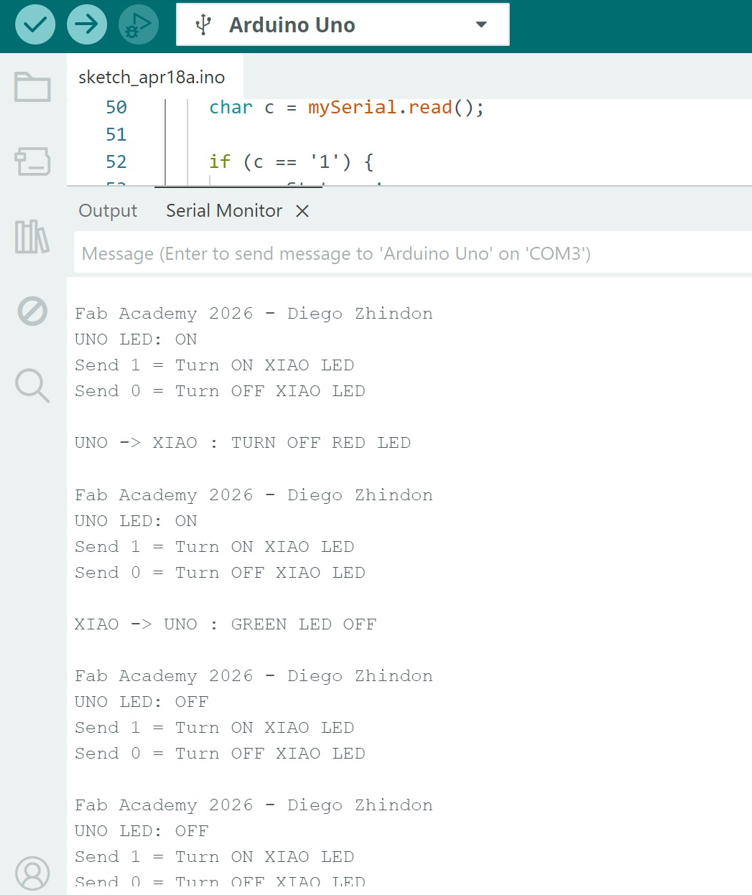
| Board | Role | Communication | Baud Rate | Output / Behavior |
|---|---|---|---|---|
| XIAO | Transmitter / receiver | UART | 9600 | Data exchange and response through serial communication |
| Arduino UNO | Transmitter / receiver | UART | 9600 | Receives values and executes the intended control logic |
XIAO Code
#include
HardwareSerial mySerial(1); // UART1 on XIAO
const int redLed = D2;
bool redState = false;
#define XIAO_RX D7
#define XIAO_TX D6
void showMenu() {
Serial.println("Fab Academy 2026 - Diego Zhindon");
Serial.print("XIAO LED: ");
Serial.println(redState ? "ON" : "OFF");
Serial.println("Send 1 = Turn ON UNO LED");
Serial.println("Send 0 = Turn OFF UNO LED");
Serial.println();
}
void setup() {
pinMode(redLed, OUTPUT);
digitalWrite(redLed, LOW);
Serial.begin(9600); // USB serial monitor
mySerial.begin(9600, SERIAL_8N1, XIAO_RX, XIAO_TX); // RX, TX pins
delay(1000);
showMenu();
}
void loop() {
// Send command from PC to UNO
if (Serial.available()) {
char c = Serial.read();
if (c == '1' || c == '0') {
mySerial.write(c);
if (c == '1') {
Serial.println("XIAO -> UNO : TURN ON GREEN LED");
} else {
Serial.println("XIAO -> UNO : TURN OFF GREEN LED");
}
Serial.println();
showMenu();
}
}
// Receive command from UNO
if (mySerial.available()) {
char c = mySerial.read();
if (c == '1') {
redState = true;
digitalWrite(redLed, HIGH);
Serial.println("UNO -> XIAO : RED LED ON");
Serial.println();
showMenu();
}
else if (c == '0') {
redState = false;
digitalWrite(redLed, LOW);
Serial.println("UNO -> XIAO : RED LED OFF");
Serial.println();
showMenu();
}
}
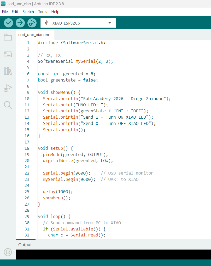
} Arduino UNO Code
#include

        // RX, TX
        SoftwareSerial mySerial(2, 3);

        const int greenLed = 8;
        bool greenState = false;

        void showMenu() {
          Serial.println("Fab Academy 2026 - Diego Zhindon");
          Serial.print("UNO LED: ");
          Serial.println(greenState ? "ON" : "OFF");
          Serial.println("Send 1 = Turn ON XIAO LED");
          Serial.println("Send 0 = Turn OFF XIAO LED");
          Serial.println();
        }

        void setup() {
          pinMode(greenLed, OUTPUT);
          digitalWrite(greenLed, LOW);

          Serial.begin(9600);    // USB serial monitor
          mySerial.begin(9600);  // UART to XIAO

          delay(1000);
          showMenu();
        }

        void loop() {
          // Send command from PC to XIAO
          if (Serial.available()) {
            char c = Serial.read();

            if (c == '1' || c == '0') {
              mySerial.write(c);

              if (c == '1') {
                Serial.println("UNO -> XIAO : TURN ON RED LED");
              } else {
                Serial.println("UNO -> XIAO : TURN OFF RED LED");
              }

              Serial.println();
              showMenu();
            }
          }

          // Receive command from XIAO
          if (mySerial.available()) {
            char c = mySerial.read();

            if (c == '1') {
              greenState = true;
              digitalWrite(greenLed, HIGH);
              Serial.println("XIAO -> UNO : GREEN LED ON");
              Serial.println();
              showMenu();
            }
            else if (c == '0') {
              greenState = false;
              digitalWrite(greenLed, LOW);
              Serial.println("XIAO -> UNO : GREEN LED OFF");
              Serial.println();
              showMenu();
            }
          }
        }
This second practical test was more complete than a simple serial monitor interaction because it required electrical compatibility, correct TX/RX crossing, common ground, matching baud rate, and an appropriate workflow for uploading programs while using the hardware UART pins.
7. Programming Foundations in Arduino IDE
Since most of the boards in the group were programmed with Arduino IDE, it is useful to document the basic structure of Arduino-style C/C++ programming. This helps explain how embedded logic is organized and executed.
7.1 Structure of an Arduino Sketch
| Element | Meaning | Role |
|---|---|---|
setup() |
Runs once | Initialization of pins, serial communication, and libraries |
loop() |
Runs repeatedly | Main embedded behavior and repeated system logic |
7.2 Variables, Constants, and Functions
| Element | Meaning | Example |
|---|---|---|
| Variable | Value that can change | int state = 0; |
| Constant | Fixed value | const int ledPin = 13; |
| Function | Reusable code block | digitalWrite() |
7.3 Common Data Types
| Type | Example | Use |
|---|---|---|
int |
int x = 1; |
Whole numbers |
float |
float t = 23.5; |
Decimals |
char |
char c = 'A'; |
Characters |
bool |
bool on = true; |
Logic |
7.4 Common Arduino Functions
| Function | Purpose |
|---|---|
pinMode() |
Configures a pin as input or output |
digitalWrite() |
Writes HIGH or LOW to an output pin |
digitalRead() |
Reads digital input state |
analogRead() |
Reads analog input values |
delay() |
Pauses execution |
Serial.begin() |
Starts serial communication |
Serial.print() |
Sends text or values |
Serial.read() |
Reads received serial data |
7.5 Libraries and Language Options
Most of the practical work in the group used Arduino-style C/C++, but embedded platforms can support other languages and frameworks depending on their architecture and memory resources.
| Language / Option | Where It Can Be Used | Comment |
|---|---|---|
| C / C++ | Arduino UNO, Nano, ESP32 boards, XIAO | Main language used by the group for this week |
| Python | Raspberry Pi 5 | Useful in Linux-based scripting and GPIO control |
| MicroPython | Some microcontroller families | Useful for rapid prototyping on supported boards |
| CircuitPython | Some supported ecosystems | Readable and beginner-friendly in compatible environments |
Libraries simplify access to peripherals such as serial communication, I2C, SPI, sensors, PWM outputs, and display modules. However, not all libraries are portable across all architectures, so board compatibility must always be verified.
8. Serial Monitor and Communication
The Serial Monitor allows interaction between the user and the board. It is essential for debugging, testing logic, and sending commands to the system.
| Feature | Purpose |
|---|---|
| Send data | User interaction |
| Receive data | Debugging output |
| Baud rate | Defines communication speed |
| Line ending options | Defines message termination format |
Baud Rate: Both devices must use the same baud rate. In this assignment, the tests were configured at 9600 baud. If the baud rate does not match, communication will fail or produce incorrect characters.
9. Communication Basics
9.1 UART Communication
UART is a serial communication protocol that uses two main lines and a common electrical reference. It is widely used in embedded systems for board-to-board communication, debugging, and interaction with peripherals.
- TX: Transmit data
- RX: Receive data
- GND: Common reference
9.2 Logic-Level Compatibility
| Board | Logic Level | Implication |
|---|---|---|
| Arduino UNO | 5V | Can damage 3.3V-only inputs if connected directly |
| XIAO ESP32 | 3.3V | Requires careful interfacing with 5V systems |
Connecting a 5V signal directly to a 3.3V input can damage the board. For this reason, voltage adaptation using a voltage divider or logic level shifter is required for safe communication.
9.3 ISP and Other Interfaces
Besides UART, embedded systems may also use interfaces such as SPI, I2C, and ISP depending on the board and the programming method. In AVR-based systems, ISP is especially important because it allows in-system programming through dedicated signals.
| Signal | Function |
|---|---|
| MISO | Master In Slave Out |
| MOSI | Master Out Slave In |
| SCK | Clock signal |
| RESET | Programming control / reset line |
| VCC | Power reference |
| GND | Ground reference |
10. Common Errors
10.1 IDE and Setup Errors
- Wrong board selected in the IDE
- Wrong serial port selected
- ESP32 package not installed for XIAO or ESP boards
- Missing or incompatible libraries
- Upload attempted with incorrect board package
10.2 Wiring and Hardware Errors
- TX and RX connected incorrectly
- No shared GND
- LED polarity reversed
- Wrong resistor placement in the voltage divider
- Loose jumper wires or poor breadboard contact
- Wrong pin numbers used in code
10.3 Communication Errors
- Baud rate mismatch between sender and receiver
- Serial Monitor configured with wrong baud rate
- Wrong line ending selection in Serial Monitor
- Incorrect parsing of received characters
- Ignoring logic-level mismatch between 5V and 3.3V devices
- Trying to upload code while TX/RX lines are still connected between boards
When using the hardware TX/RX pins for UART communication, disconnect them before uploading the code. After the program is uploaded successfully, reconnect the communication lines and repeat the test.
11. References
The group assignment was supported by the individual weekly documentation of each member. These pages were used as a reference for platform comparison, workflow analysis, and practical test evidence.
12. Conclusions
- Embedded programming involves not only writing code, but also understanding the relationship between hardware architecture, logic levels, communication protocols, and development environments.
- Even when multiple boards are programmed using the same environment, such as Arduino IDE, their internal architectures and electrical characteristics significantly affect compatibility, workflow, and available functionality.
- The comparison between Arduino UNO/Nano and ESP32/XIAO boards shows the transition from simple and accessible AVR-based systems to more advanced and flexible platforms with broader communication and processing capabilities.
- The Raspberry Pi 5 represents a different embedded development model, where the workflow is based on a Linux operating system, scripting tools, and higher-level software interaction rather than direct microcontroller firmware upload.
- The Serial Monitor proved to be a fundamental debugging and interaction tool, enabling real-time communication between the user and the embedded system for testing and validation.
- The first practical test demonstrated that serial communication can be used as an effective user input mechanism to control hardware outputs, reinforcing the integration between software logic and physical devices.
- The UART communication test between XIAO and Arduino UNO confirmed that board-to-board communication is feasible, but only when the system is configured carefully with matching baud rate, correct TX/RX cross-connection, and shared ground.
- Logic-level compatibility is a critical engineering consideration in mixed-board communication. The use of a voltage divider to adapt a 5V signal to approximately 3.40V demonstrated the importance of electrical protection and signal adaptation.
- The calculation and implementation of the voltage divider using 4.7kΩ and 10kΩ resistors reinforced the practical use of basic electronics formulas in a real embedded systems scenario.
- A practical limitation was identified when using the hardware TX/RX pins: program upload may fail if those lines remain connected during programming. This highlights the importance of understanding shared resources in microcontroller systems.
- The documentation process itself is a key part of the engineering workflow, since it requires structuring experiments, validating results, identifying problems, and clearly communicating technical decisions and solutions.
- Working as a group enabled a broader comparison of platforms, workflows, and communication methods, providing a more complete understanding of embedded programming than individual experimentation alone.