NODO

Toolchains, Development Workflows and Microcontroller Programming
For the group assignment, the lab explored development workflows and communication concepts between embedded platforms. This week is strongly focused on understanding toolchains, pin configurations, architecture differences, and board-to-board communication.
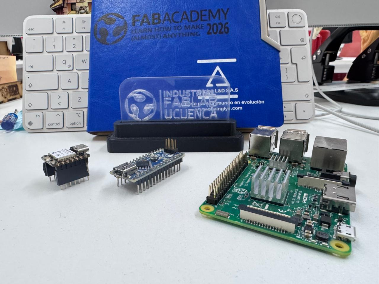
This individual page focuses on comparing Arduino UNO, Seeed XIAO, and Raspberry Pi 5, while the group assignment complements this comparison through practical communication testing between devices.
Open Group AssignmentMicrocontrollers Analyzed:
This individual page focuses on comparing Arduino UNO, Seeed XIAO, and Raspberry Pi 5, while the group assignment complements this comparison through practical communication testing between devices.
| Feature | ESP32-S2 | XIAO ESP32-C3 | Arduino Nano |
|---|---|---|---|
| Architecture | Xtensa LX7 (32-bit) | RISC-V (32-bit) | AVR (8-bit) |
| Clock Speed | Up to 240 MHz | 160 MHz | 16 MHz |
| Flash Memory | 4MB | 4MB | 32 KB |
| RAM | 320 KB | 400 KB | 2 KB |
| Wireless | WiFi | WiFi + BLE | None |
| Debug Interface | USB CDC / JTAG | USB CDC | UART Serial |
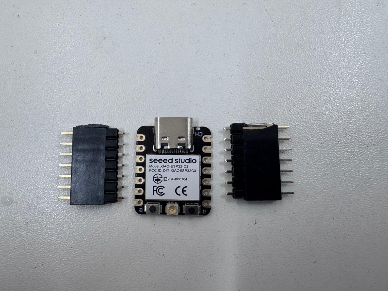
Controller used for analysis: The Seeed XIAO ESP32-C3 is a compact microcontroller board based on the ESP32-C3 chip, featuring Wi-Fi and Bluetooth Low Energy (BLE) connectivity. It is designed for low-power embedded applications, offering efficient GPIO control, wireless communication, and high performance in a small form factor.
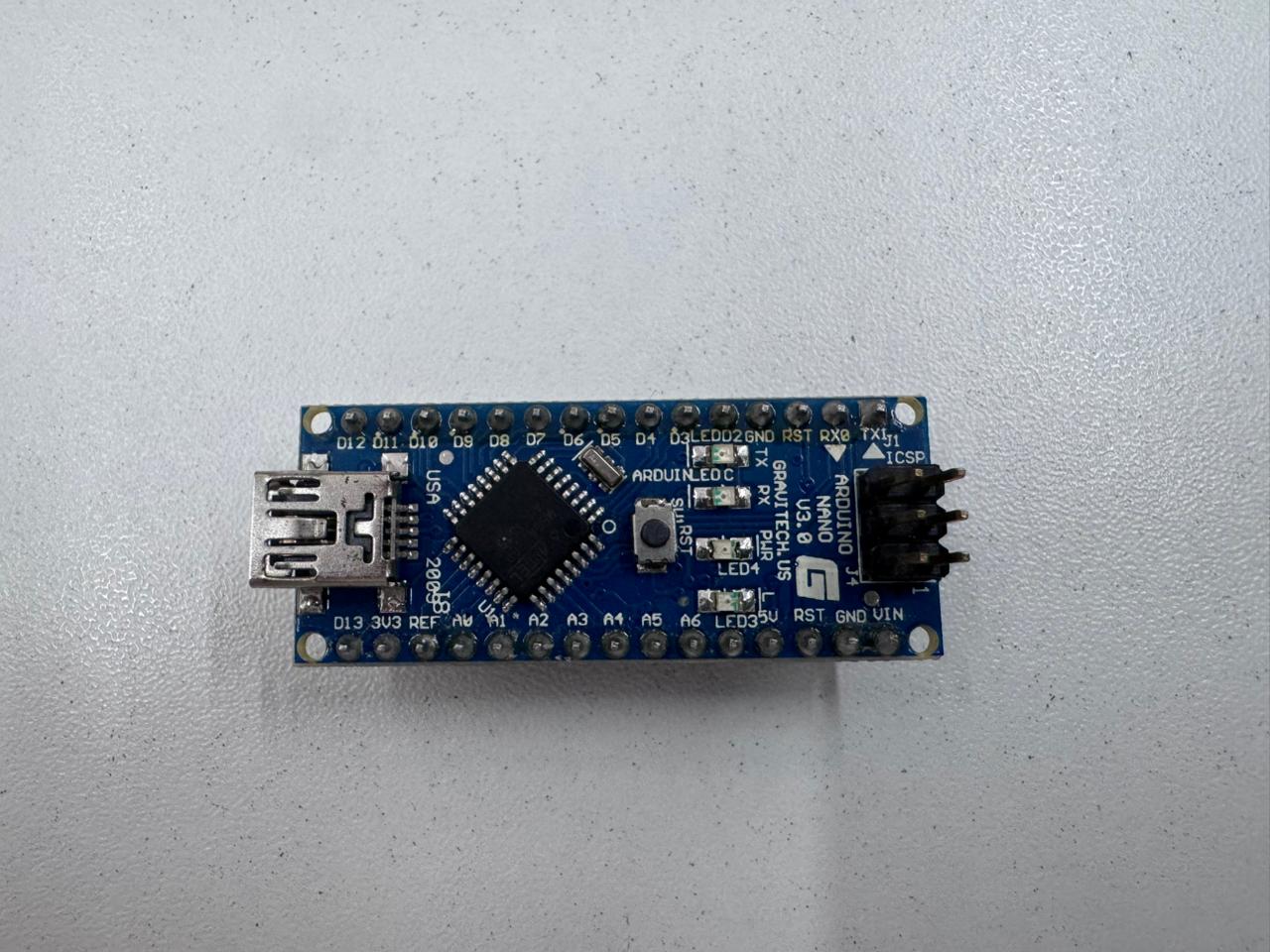
Controller used for analysis: This individual page focuses on Arduino NANO, highlighting its role in embedded programming, GPIO control, and basic communication testing as part of the development process.
| Criteria | Arduino IDE | PlatformIO | ESP-IDF |
|---|---|---|---|
| Ease of Use | High | Medium | Low |
| Flexibility | Medium | High | Very High |
| Compilation Control | Limited | Advanced | Full Control |
| Debugging Capabilities | Basic Serial | Integrated Debugger | Professional JTAG Debugging |
| Best For | Rapid Prototyping | Intermediate/Advanced | Industrial/Advanced IoT |
| Compilation | One-click compile/upload | Configurable build tasks | Manual and highly configurable |
| SDK Support | Arduino Core | Multiple frameworks (Arduino, ESP-IDF, etc.) | Native ESP-IDF SDK |
| Optimization | Limited | Moderate (configurable) | High (fine-tuned control) |
| Debugging | Serial Monitor | Advanced debugging tools | Full JTAG and low-level debugging |
| Build System | Simplified (hidden) | Based on CMake/PlatformIO Core | CMake-based (full control) |
| Library Access | Extensive, easy integration | Very extensive, managed dependencies | ESP-IDF components (modular) |
| Ease of Use | Beginner-friendly | Requires some setup | Steep learning curve |
The ESP32 family allows advanced debugging using JTAG and FreeRTOS integration, while the Arduino Nano workflow is simpler but more limited in professional debugging tools.
This section presents the development workflow for embedded programming using the Seeed XIAO ESP32-C3, following a structured approach from simulation to physical implementation. The process integrates design, coding, testing, and validation to ensure reliable system behavior.
The workflow begins with circuit design using Wokwi, where components such as LEDs, resistors, and inputs are virtually connected to the ESP32-C3. This stage allows validation of logic, pin configuration, and expected behavior before working with real hardware.
The program is written in the Arduino IDE, configuring GPIO pins, defining input/output behavior, and implementing control logic. Serial communication is used for monitoring and debugging.
The ESP32 board package is installed in the Arduino IDE, and the Seeed XIAO ESP32-C3 is selected along with the appropriate communication port. This ensures compatibility between the development environment and the hardware.
The code is compiled and uploaded to the physical board via USB. The IDE transfers the program into the microcontroller’s memory, enabling standalone execution.
The circuit is assembled on a breadboard, connecting all components according to the design. This stage allows real-world testing and validation of electrical connections and system response.
The system is tested under real conditions. Any discrepancies between simulation and physical behavior are corrected through iterative debugging, adjusting code, wiring, or timing parameters as needed.
The workflow concludes with a final demonstration, confirming that the system operates according to the programmed logic. This step validates the integration of simulation, programming, and hardware implementation.
This structured workflow ensures a reliable transition from digital design to physical prototyping, reducing errors and improving efficiency in embedded system development.
The datasheet of the ATmega328P (Arduino Nano) and ESP32-S2 was reviewed. Key sections analyzed:
Understanding the datasheet allowed correct configuration of registers, communication interfaces, and peripheral usage.
A program was developed to:
const int buttonPin = 4;
const int ledPin = 2;

void setup() {
  pinMode(buttonPin, INPUT_PULLUP);
  pinMode(ledPin, OUTPUT);
  Serial.begin(115200);
}

void loop() {
  int buttonState = digitalRead(buttonPin);

  if (buttonState == LOW) {
    digitalWrite(ledPin, HIGH);
    Serial.println("Button Pressed - LED ON");
  } else {
    digitalWrite(ledPin, LOW);
    Serial.println("Button Released - LED OFF");
  }

  delay(200);
}
The system successfully interacted with physical input (button), controlled an output (LED), and communicated through USB serial.
Using ESP32 WiFi libraries, the board connected to a local network and transmitted status messages via TCP.
This demonstrates wireless embedded communication capability, which is not available on the Arduino Nano without additional modules.
Go to the official Arduino website and download the latest version for your operating system.
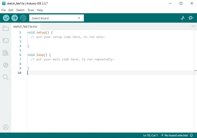
Development platform: Arduino IDE is an open-source programming environment used to write, compile, and upload code to microcontroller boards. It provides a simple interface, built-in libraries, and serial monitoring tools, making it widely used for embedded systems development and rapid prototyping.
Run the installer and follow the installation wizard:
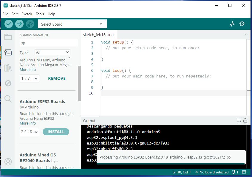
Installation process: To use a microcontroller board in the Arduino IDE, it is necessary to install the corresponding board package through the Board Manager. This involves adding the board manager URL in the preferences, searching for the specific board (e.g., ESP32 or Seeed XIAO), and installing the required drivers and libraries. Once installed, the board can be selected along with the correct port, enabling code upload and communication with the device.
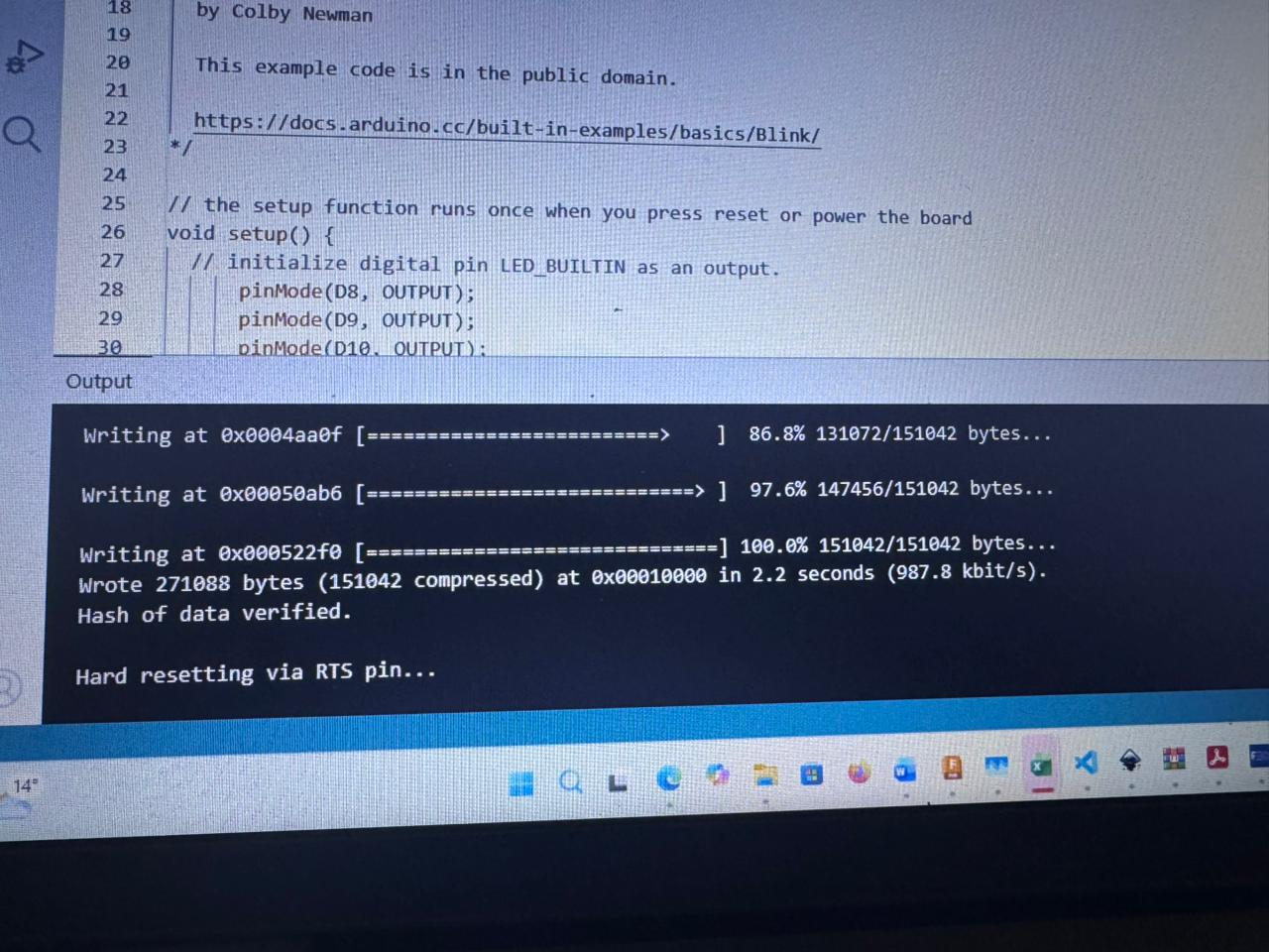
Upload process: The program is transferred to the physical Seeed XIAO ESP32-C3 from the computer using the Arduino IDE via a USB connection. After selecting the correct board and communication port, the code is compiled and uploaded. During this process, the IDE establishes a serial connection with the microcontroller, flashing the program into its memory. Once completed, the board executes the code independently, confirming successful communication between the computer and the device.
Tools → Board → ESP32 Arduino → Select "XIAO_ESP32C3"
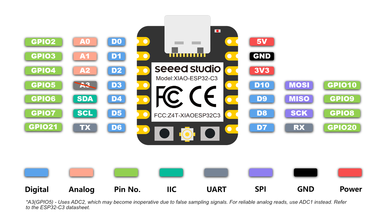
Pinout description: The Seeed XIAO ESP32-C3 features a compact and versatile pinout that includes digital GPIO pins, analog inputs, and communication interfaces such as UART, I2C, and SPI. Each pin can serve multiple functions depending on the configuration, allowing flexibility in embedded applications. It also includes dedicated power pins (3.3V and GND) and supports PWM for output control. Understanding the pin mapping is essential to correctly connect components and ensure proper operation of the circuit.
For this assignment, we selected and used Wokwi as the main tool for circuit board design and simulation. Wokwi is an online platform that allows users to design, simulate, and test electronic circuits in a virtual environment before implementing them physically.
Using Wokwi, we were able to create circuit schematics, connect components such as microcontrollers, LEDs, and sensors, and verify their behavior through real-time simulation. This significantly reduces errors and improves understanding of circuit functionality prior to fabrication.
One of the main advantages of Wokwi is its accessibility, as it runs directly in the browser without requiring installation. Additionally, it supports code integration (e.g., Arduino), allowing simultaneous testing of both hardware connections and embedded programming.
Overall, Wokwi proved to be an effective tool for learning and validating circuit designs, bridging the gap between conceptual design and real-world implementation.
Go to wokwi.com and create a new ESP32-C3 project.
Simulation tool: Wokwi is an online platform used to simulate electronic circuits and embedded systems in a virtual environment. It allows users to design circuits, connect components such as microcontrollers, sensors, and actuators, and test their behavior in real time using code (e.g., Arduino). This tool helps validate designs, debug programs, and reduce errors before implementing the circuit in physical hardware.
| Component | Quantity |
|---|---|
| LED Red | 1 |
| LED Yellow | 1 |
| LED Green | 1 |
| Resistors (220Ω) | 3 |
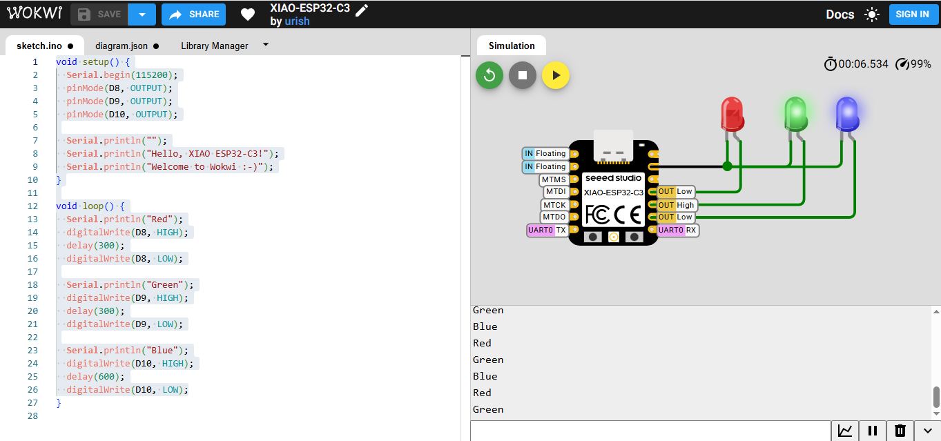
Simulation video: This video shows the circuit running in Wokwi, where the behavior of the components is validated in a virtual environment. It demonstrates how the programmed logic operates correctly before being implemented on physical hardware, allowing verification of connections, timing, and functionality.
The following program controls three LEDs connected to pins D8, D9, and D10 of the Seeed XIAO ESP32-C3. It turns them on sequentially while sending messages through the serial monitor to indicate the current state.
void setup() {
  Serial.begin(115200);
  pinMode(D8, OUTPUT);
  pinMode(D9, OUTPUT);
  pinMode(D10, OUTPUT);

  Serial.println("");
  Serial.println("Hello, XIAO ESP32-C3!");
  Serial.println("Welcome to Wokwi :-)");
}

void loop() {
  Serial.println("Red");
  digitalWrite(D8, HIGH);
  delay(300);
  digitalWrite(D8, LOW);

  Serial.println("Green");
  digitalWrite(D9, HIGH);
  delay(300);
  digitalWrite(D9, LOW);

  Serial.println("Blue");
  digitalWrite(D10, HIGH);
  delay(600);
  digitalWrite(D10, LOW);
}
The setup() function runs once when the microcontroller starts. It initializes the system configuration:
The loop() function runs continuously. It defines the main behavior of the system:
HIGH),
stays on for 300 ms, and then turns OFF.
The program creates a sequential LED pattern, where each LED turns on one after another. The delays control the duration of each light, with the blue LED staying on longer to create variation. At the same time, serial messages provide real-time feedback, which is useful for debugging and monitoring.
This loop repeats indefinitely, creating a continuous light sequence. This demonstrates basic concepts of GPIO control, timing using delays, and serial communication in embedded systems.
Program transfer: The code is uploaded from the Arduino IDE to the Seeed XIAO ESP32-C3 via USB connection. After selecting the correct board and port, the program is compiled and transferred to the microcontroller’s memory. Once the upload is complete, the board runs the code autonomously, confirming successful communication and proper configuration.
| Component | Description |
|---|---|
| XIAO ESP32-C3 | Main microcontroller |
| LEDs | Red (D8), Yellow (D9), Green (D10) |
| Resistors | 220Ω current limiting resistors |
| Protoboard | Assembly platform |
| Jumper Wires | Connections |
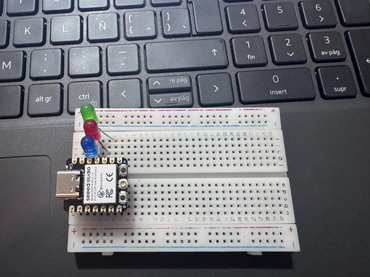
Breadboard connection: The Seeed XIAO ESP32-C3 is connected on a protoboard to facilitate rapid prototyping without soldering. Components such as LEDs, resistors, and input devices are interconnected using jumper wires, following the defined circuit design. This setup allows easy modification, testing, and debugging of the system before final implementation.
This section presents the final demonstration of the developed circuit assembled on a breadboard. The video shows the complete operation of the system, including component interaction and response according to the programmed logic.
The circuit was programmed using the Arduino IDE, and all functionalities were tested in real conditions. As observed in the demonstration, the behavior of the system matches the expected results defined during the design and coding stages.
Hero shot – Final demonstration: This image/video highlights the final implementation of the system, showing the circuit assembled on the protoboard and operating as expected. It demonstrates that the behavior matches the logic programmed in the Arduino IDE, validating correct integration between hardware and software.
The correct operation confirms that the configuration of connections, code implementation, and component integration were successfully executed. This final test validates both the design process and the embedded programming workflow.
This section explains the relationship between the implemented code and the physical hardware using the Seeed XIAO ESP32-C3. The system is based on controlling three LEDs through digital outputs, where each instruction in the code directly corresponds to a physical action in the circuit.
The circuit was assembled on a breadboard using the following pin configuration:
Each LED is connected in series with a resistor to limit current and protect the components. The GPIO pins act as digital outputs, switching between HIGH (3.3V) and LOW (0V) to control the LEDs.
In the code, the pins D8, D9, and D10 are configured as outputs using
pinMode(). When the program executes digitalWrite(HIGH), the
corresponding pin supplies voltage, turning the LED ON. When LOW is written,
the LED turns OFF.
The sequential logic implemented in the loop() function creates a pattern where
each LED is activated one after another, directly reflecting the wiring configuration on the
breadboard.
The system was first validated using simulation (Wokwi), followed by real hardware testing. Each LED was tested individually to confirm correct pin assignment, and then the full sequence was executed to verify timing and synchronization.
This implementation demonstrates a clear relationship between software and hardware, where each line of code directly controls a physical component. The iterative testing and debugging process improved reliability and ensured that the system behaves exactly as intended.
Regards
This practice demonstrates embedded programming fundamentals including GPIO configuration, serial communication, digital output control, simulation before physical implementation, testing workflow, and debugging. Beyond the technical implementation, it also strengthened our understanding of how software and hardware interact in real time, reinforcing the importance of structured thinking when developing embedded systems.
One of the main challenges encountered was the correct configuration of GPIO pins, especially when working across different platforms where pin mapping and logic levels vary. This initially caused unexpected behavior in the circuits. To overcome this, datasheets were carefully reviewed and pin diagrams were analyzed in detail, ensuring that each connection matched the intended function.
Another difficulty was related to serial communication and debugging. In some cases, the system did not respond as expected, making it hard to identify whether the issue was in the code or in the wiring. This was resolved by implementing incremental testing: validating each module separately, using serial print statements for monitoring, and relying on simulation tools before moving to physical implementation.
Additionally, transitioning from simulation to real hardware introduced discrepancies, such as timing issues or unstable connections. These were addressed through iterative testing, adjusting delays in the code, and ensuring proper wiring and power supply stability.
In conclusion, this experience highlighted that debugging is an essential part of embedded systems development. By combining simulation, systematic testing, and careful analysis of both code and hardware, we were able to successfully identify and resolve issues, leading to a more robust and reliable implementation.
The workflow followed: Simulation → Code Debugging → Serial Monitoring → Physical Assembly → Final Validation.
The embedded system was assembled on a breadboard including:
The hardware assembly was tested and validated before final code deployment.