
Week 04
Embedded Programming
Microcontrollers, GPIO, Simulation, and Local Communication Concepts
1. Checklist
- ✅ Linked the group assignment page
- ✅ Reviewed and documented microcontroller datasheet information
- ✅ Compared three embedded platforms
- ✅ Programmed boards to control local outputs
- ✅ Included simulation where applicable
- ✅ Documented software, code, wiring, and physical tests
- ✅ Added downloadable source files and videos
2. Group Assignment
For the group assignment, the lab explored development workflows and communication concepts between embedded platforms. This week is strongly connected to understanding toolchains, pin usage, architecture differences, and board-to-board communication.
This individual page focuses on comparing Arduino UNO, Seeed XIAO, and Raspberry Pi 5, while the group assignment complements that comparison through communication testing.
3. Individual Assignment
For this assignment, I worked with three platforms: an Arduino UNO, a Seeed XIAO board, and a Raspberry Pi 5. The goal was to compare their characteristics, review their pinouts, and develop simple LED-based programs to understand digital output, PWM behavior, and GPIO control using different toolchains.
4. Platform Comparison
Before programming, I compared the three platforms using the most relevant embedded characteristics. This helped define what each board is best suited for and how each one fits into prototyping workflows.
| Platform | Type | Main Voltage | GPIO / I/O | Protocols | Programming Environment | Best Use |
|---|---|---|---|---|---|---|
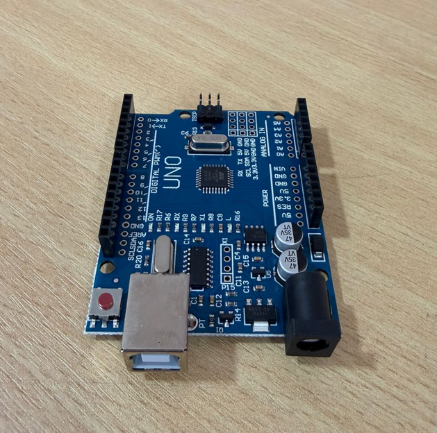
| Arduino UNO | Microcontroller board | 5V logic | Digital + analog I/O | UART, I2C, SPI, PWM | Arduino IDE | Basic embedded programming and fast prototyping |
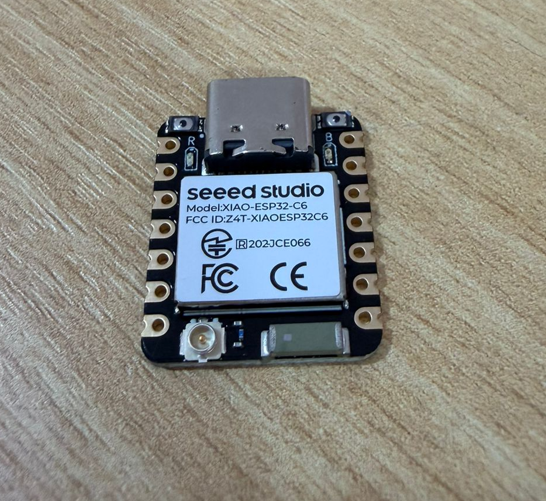
| Seeed XIAO ESP32-C6 | Compact microcontroller board | 3.3V logic | Compact multifunction GPIO | UART, I2C, SPI, PWM | Arduino IDE | Small embedded applications and compact smart devices |
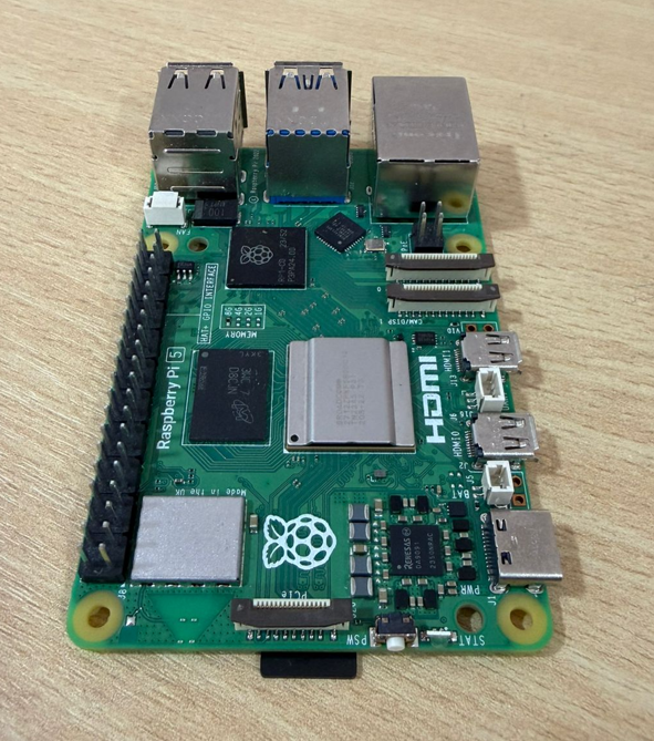
| Raspberry Pi 5 | Single-board computer | 3.3V GPIO | 40-pin header GPIO | UART, I2C, SPI, PWM, Linux networking | Python | Higher-level processing, Linux applications, and GPIO control |
5. Datasheet and Pinout Review
Reviewing the pinout is essential before programming because it defines power pins, GPIO behavior, communication interfaces, and safe connection points for components such as LEDs and resistors.
5.1 Arduino UNO Pinout
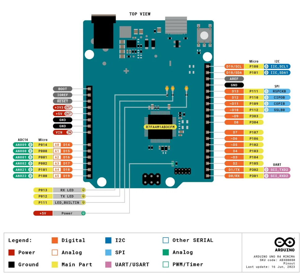
The most important elements for this assignment are the 5V and GND pins, digital outputs, PWM-capable pins, and the communication pins used for UART, I2C, and SPI.
| Pin / Area | Function | Relevance in this assignment |
|---|---|---|
| 5V | Power output | Used to supply the breadboard rails if needed |
| GND | Ground reference | Required for both LEDs and resistors |
| D8 | Digital output | Green LED output |
| D9 | Digital output / PWM | Red LED output |
| A0–A5 | Analog inputs | Available for future sensor integration |
| SDA / SCL | I2C | Relevant for group communication work |
| MOSI / MISO / SCK | SPI | Important embedded communication option |
| TX / RX | UART | Used for serial communication and monitoring |
5.2 Seeed XIAO Pinout
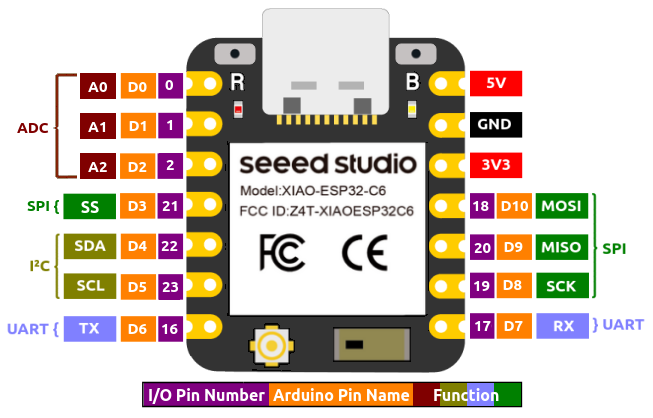
The XIAO board offers a very compact form factor, so each pin becomes more multifunctional. For this assignment, the most relevant areas are 3.3V, GND, digital/PWM-capable pins, and communication interfaces.
| Pin / Area | Function | Relevance in this assignment |
|---|---|---|
| 3V3 | Main logic voltage | Reference for the board logic level |
| 5V / VBUS | Power input/output reference | Useful depending on USB-powered configuration |
| GND | Ground | Common reference for both LEDs |
| D2 | PWM-capable output | Green LED PWM output |
| D3 | PWM-capable output | Red LED PWM output |
| SDA / SCL | I2C | Important for compact board communication |
| TX / RX | UART | Used for serial communication |
| MOSI / MISO / SCK | SPI | Available for peripheral communication |
5.3 Raspberry Pi 5 Pinout
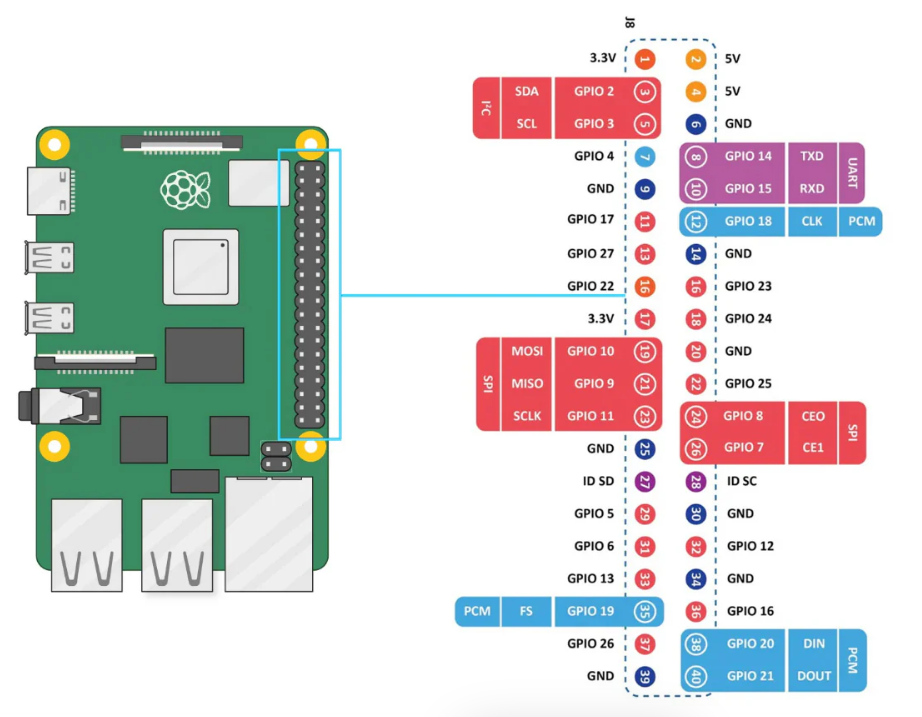
Unlike the Arduino and XIAO, the Raspberry Pi 5 is a single-board computer running Linux. Its GPIO header works at 3.3V logic and should be used carefully when wiring external components.
| Pin / Area | Function | Relevance in this assignment |
|---|---|---|
| Pin 1 / 17 | 3.3V power | Logic reference for GPIO ecosystem |
| Pin 2 / 4 | 5V power | Available power source if needed |
| Pin 14 | GND | Ground used in the LED circuit |
| GPIO17 (Pin 11) | Digital GPIO | Red LED output |
| GPIO27 (Pin 13) | Digital GPIO | Green LED output |
| GPIO2 / GPIO3 | I2C SDA / SCL | Important for communication workflows |
| GPIO14 / GPIO15 | UART TX / RX | Serial communication option |
| GPIO10 / 9 / 11 | SPI | Peripheral communication support |
6. Programming and Physical Tests
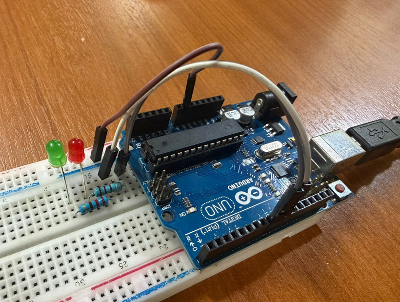
For all three cases, I used a red LED and a green LED, each one connected with a 220 Ω resistor. The goal was to keep the circuits simple and focused on output control, while still demonstrating different programming approaches in each platform.
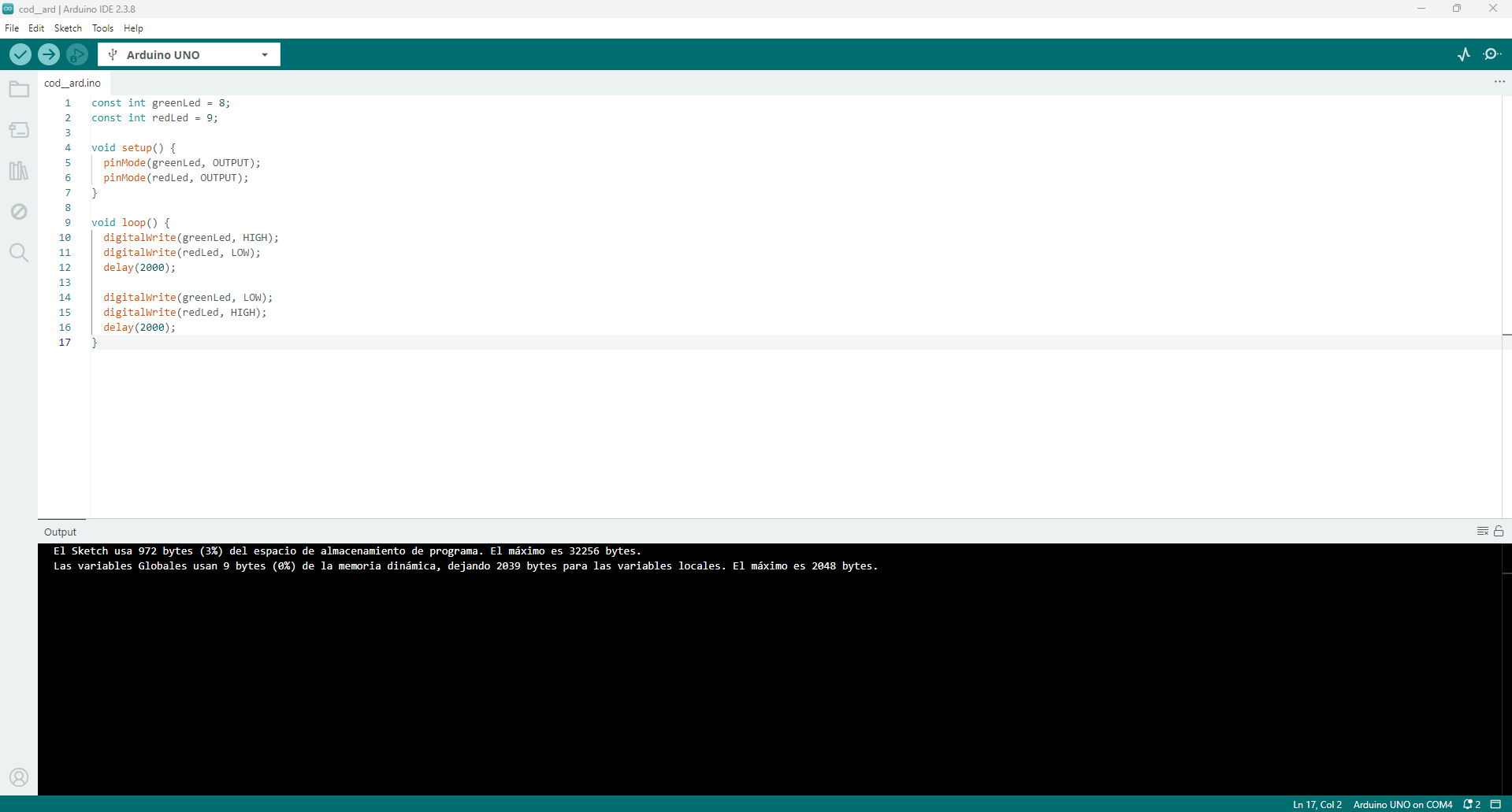
6.1 Arduino UNO
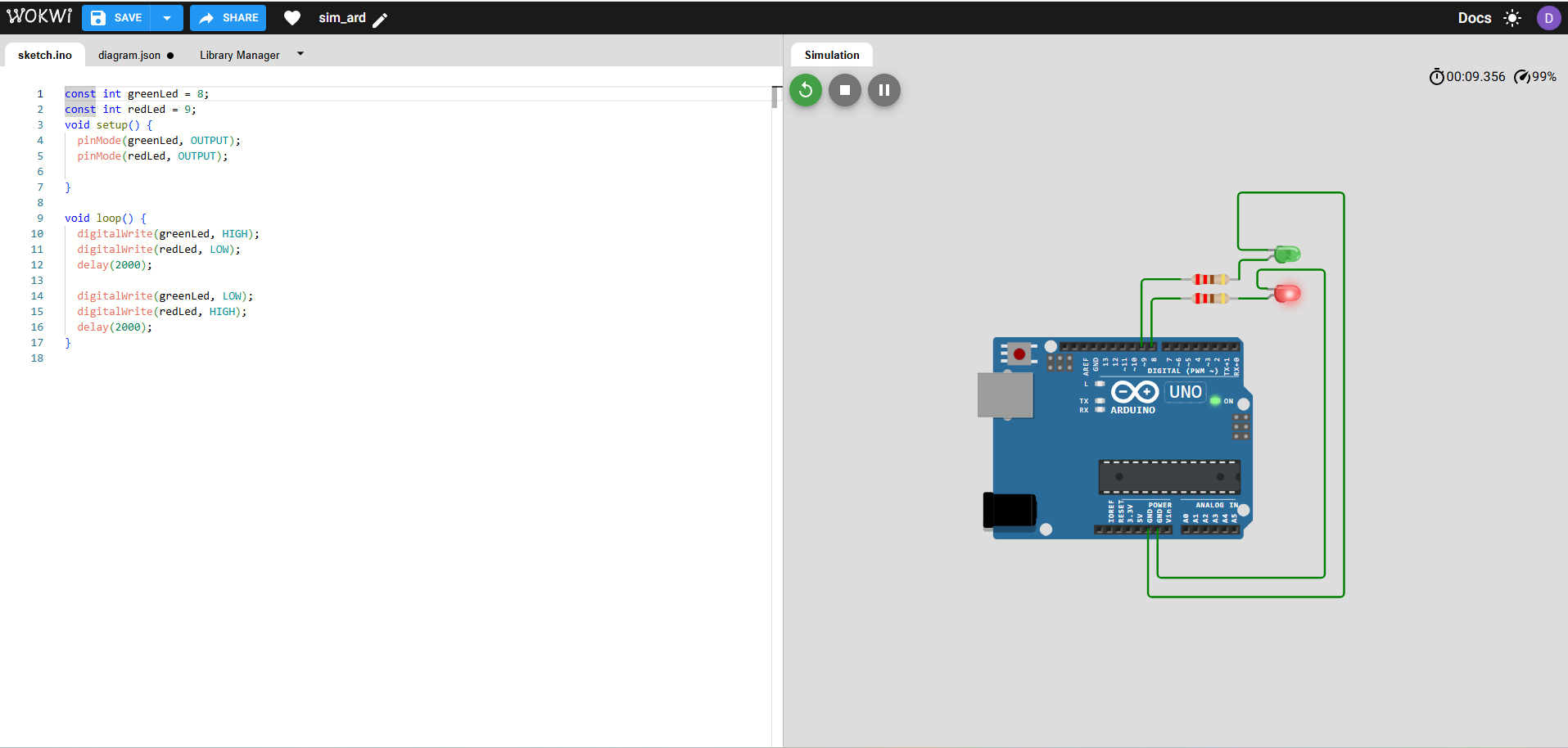
In the Arduino UNO test, two LEDs were connected to digital outputs. The program alternates the LEDs every 2 seconds: when the green LED is on, the red LED is off, and after 2 seconds they switch states.
Components and pins used
- Arduino UNO
- 1 red LED
- 1 green LED
- 2 resistors of 220 Ω
- Green LED → pin D8
- Red LED → pin D9
- Both LED cathodes connected to GND
Software used
- Open Arduino IDE.
- Select the correct board: Arduino UNO.
- Select the correct serial port.
- No extra library is required for this program.
- Write the sketch using digital outputs and delay timing.
- Compile and upload the code to the board.
Program logic
- Configure pins D8 and D9 as outputs.
- Turn the green LED on and the red LED off.
- Wait 2 seconds.
- Turn the red LED on and the green LED off.
- Wait 2 seconds.
- Repeat the sequence in an infinite loop.
Source code
const int greenLed = 8;
const int redLed = 9;

void setup() {
  pinMode(greenLed, OUTPUT);
  pinMode(redLed, OUTPUT);
}

void loop() {
  digitalWrite(greenLed, HIGH);
  digitalWrite(redLed, LOW);
  delay(2000);

  digitalWrite(greenLed, LOW);
  digitalWrite(redLed, HIGH);
  delay(2000);
}
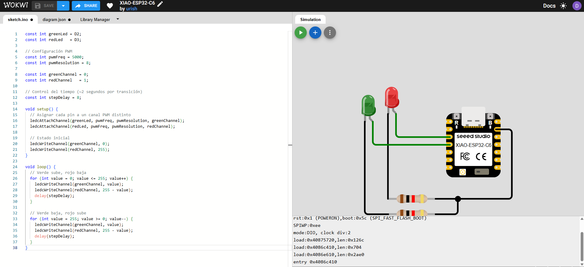
6.2 Seeed XIAO ESP32-C6
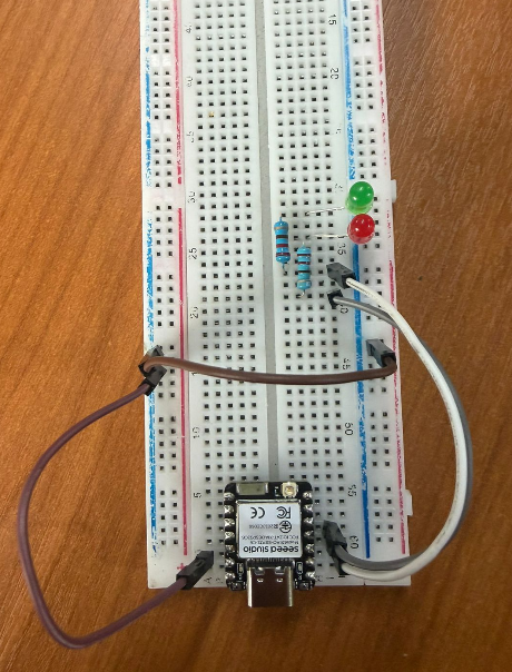
In the XIAO test, two LEDs were connected to PWM-capable pins. The objective was to create an inverse fade effect: while the green LED increases its intensity, the red LED decreases proportionally, generating a smooth looped transition.
Components and pins used
- Seeed XIAO ESP32-C6
- 1 red LED
- 1 green LED
- 2 resistors of 220 Ω
- Green LED → pin D2
- Red LED → pin D3
- Both LED cathodes connected to GND
Software used
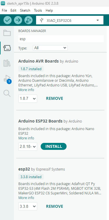
- Open Arduino IDE.
- Open Boards Manager and install the ESP32 package.
- Select the correct board model: XIAO ESP32-C6.
- Select the corresponding serial port.
- Write the PWM code using two independent PWM channels.
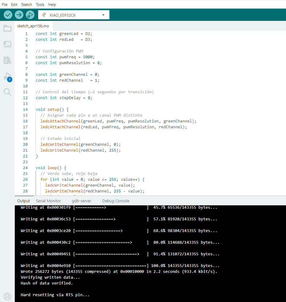
- Compile and upload the program to the board.
Program logic
- Configure D2 and D3 as PWM outputs.
- Start with the green LED at minimum brightness and the red LED at maximum brightness.
- Increase the green LED intensity step by step.
- At the same time, decrease the red LED intensity inversely.
- Repeat the opposite direction to create a smooth transition cycle.
- Keep the full sequence running in an infinite loop.
Source code
const int greenLed = D2;
            const int redLed   = D3;

            // Configuración PWM
            const int pwmFreq = 5000;
            const int pwmResolution = 8;

            const int greenChannel = 0;
            const int redChannel   = 1;

            // Control del tiempo (~2 segundos por transición)
            const int stepDelay = 8;

            void setup() {
              // Asignar cada pin a un canal PWM distinto
              ledcAttachChannel(greenLed, pwmFreq, pwmResolution, greenChannel);
              ledcAttachChannel(redLed, pwmFreq, pwmResolution, redChannel);

              // Estado inicial
              ledcWriteChannel(greenChannel, 0);
              ledcWriteChannel(redChannel, 255);
            }

            void loop() {
              // Verde sube, rojo baja
              for (int value = 0; value <= 255; value++) {
                ledcWriteChannel(greenChannel, value);
                ledcWriteChannel(redChannel, 255 - value);
                delay(stepDelay);
              }

              // Verde baja, rojo sube
              for (int value = 255; value >= 0; value--) {
                ledcWriteChannel(greenChannel, value);
                ledcWriteChannel(redChannel, 255 - value);
                delay(stepDelay);
              }
            }
6.3 Raspberry Pi 5
For the Raspberry Pi 5, I used Python to control two LEDs through GPIO pins. The sequence is simple but useful to compare GPIO scripting with microcontroller-style programming: red on / green off, then the opposite, then both on, then both off, repeating continuously.
Components and pins used
- Raspberry Pi 5
- 1 red LED
- 1 green LED
- 2 resistors of 220 Ω
- Red LED → GPIO17 (physical pin 11)
- Green LED → GPIO27 (physical pin 13)
- Ground → physical pin 14
Software used
- Use the latest stable Python 3 version available in Raspberry Pi OS. :contentReference[oaicite:1]{index=1}
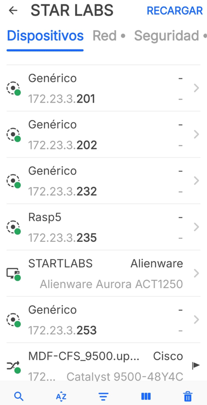
- Use the Fing application to identify the Raspberry Pi IP address in the local network.
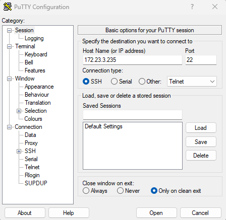
- Open PuTTY and connect to the Raspberry Pi using the detected IP: 172.23.3.235.
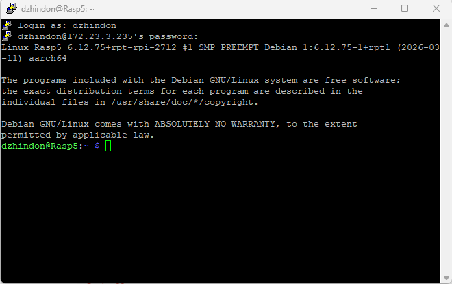
- Log in with the Raspberry Pi user name and password through the terminal console.
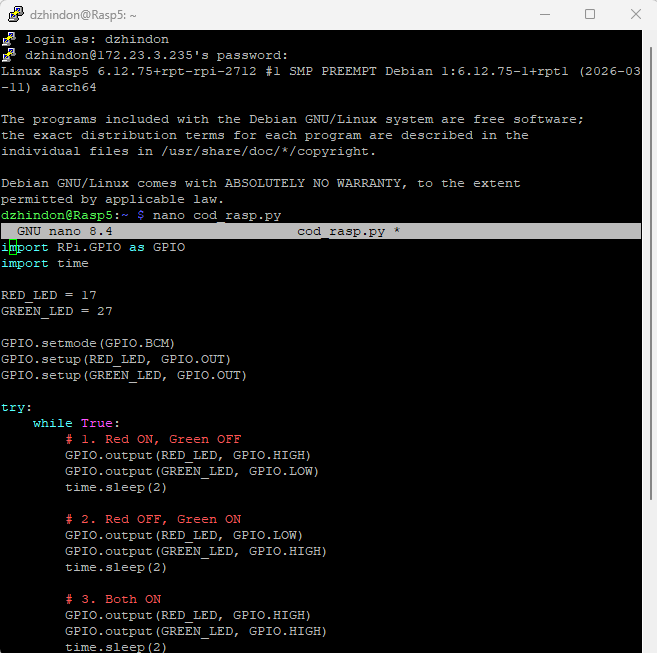
- Create the program with the command
nano cod_rasp.py. - Save the file and execute it with
sudo python3 cod_rasp.py.
Program logic
- Set GPIO17 and GPIO27 as outputs.
- Turn the red LED on and the green LED off.
- Swap the states.
- Turn both LEDs on.
- Turn both LEDs off.
- Repeat the full sequence continuously.
Main commands used
nano cod_rasp.py
sudo python3 cod_rasp.py
Source code
import RPi.GPIO as GPIO
            import time

            RED_LED = 17
            GREEN_LED = 27

            GPIO.setmode(GPIO.BCM)
            GPIO.setup(RED_LED, GPIO.OUT)
            GPIO.setup(GREEN_LED, GPIO.OUT)

            try:
                while True:
                    # 1. Red ON, Green OFF
                    GPIO.output(RED_LED, GPIO.HIGH)
                    GPIO.output(GREEN_LED, GPIO.LOW)
                    time.sleep(2)

                    # 2. Red OFF, Green ON
                    GPIO.output(RED_LED, GPIO.LOW)
                    GPIO.output(GREEN_LED, GPIO.HIGH)
                    time.sleep(2)

                    # 3. Both ON
                    GPIO.output(RED_LED, GPIO.HIGH)
                    GPIO.output(GREEN_LED, GPIO.HIGH)
                    time.sleep(2)

                    # 4. Both OFF
                    GPIO.output(RED_LED, GPIO.LOW)
                    GPIO.output(GREEN_LED, GPIO.LOW)
                    time.sleep(2)

            except KeyboardInterrupt:
                pass

            finally:
                GPIO.cleanup()
nano cod_rasp.py.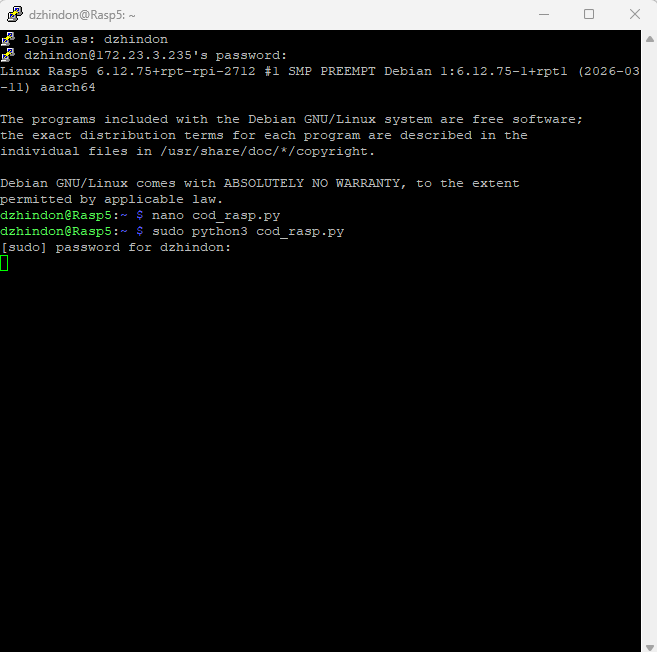
sudo python3 cod_rasp.py.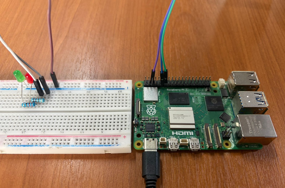
7. Toolchain Notes
Arduino UNO and XIAO were programmed in Arduino IDE, which makes uploading embedded code straightforward. The Raspberry Pi 5, on the other hand, was programmed with Python as a Linux-based GPIO workflow.
- Arduino UNO required no additional library for the LED alternation test.
- XIAO required installing the ESP32 board package before selecting the XIAO ESP32-C6 model.
- Wokwi was useful for simulation in Arduino UNO and XIAO workflows.
- Raspberry Pi 5 used Python 3 and remote access through PuTTY for execution and testing. :contentReference[oaicite:2]{index=2}
8. Reflection
- Arduino UNO is a very direct platform for learning digital outputs and basic timing logic.
- The Seeed XIAO ESP32-C6 provides a more compact solution while still supporting advanced features such as PWM.
- Raspberry Pi 5 differs from microcontrollers because it combines GPIO control with a full Linux environment.
- Reviewing pinouts before wiring is essential to avoid incorrect connections and incompatible pin usage.
- Simulation is very helpful for validating logic before assembling the real circuit, especially with Arduino and XIAO.
- Using 220 Ω resistors with LEDs is important to protect the components and keep the circuits stable.
- This comparison provides a strong base for selecting the most appropriate platform for future integration in my final project.
- This assignment helped me better understand how the microcontroller responds to inputs and executes instructions in real conditions beyond simulation.
- I learned the importance of testing step by step and debugging errors, improving the reliability and functionality of the final implementation.