Week 03 — Group Assignment
Computer-Controlled Cutting
This group assignment focused on understanding, testing, and documenting the behavior of the laser cutters available across our labs. The work includes machine identification, safety protocol, maintenance routines, focus setup, material references, engraving and cutting tests, kerf characterization, and common troubleshooting cases.
Personal Contributions
| Name | University | Activities carried out |
|---|---|---|
| Rodrigo Guamán | Universidad de Cuenca |
|
| Jenny Rojas | Universidad de Cuenca |
|
| Diego Zhindón | Universidad Politécnica Salesiana |
|
1. Checklist
- ✅ Completed safety training and documented critical safety considerations
- ✅ Identified the laser cutters available in the labs
- ✅ Documented machine setup and focus adjustment
- ✅ Characterized kerf behavior through a press-fit test
- ✅ Compared typical cutting parameters for common materials
- ✅ Tested engraving behavior on MDF and acrylic
- ✅ Documented common machine errors and troubleshooting notes
- ✅ Added cross-lab references from the individual documentation of team members
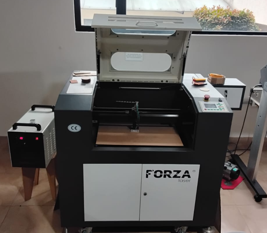
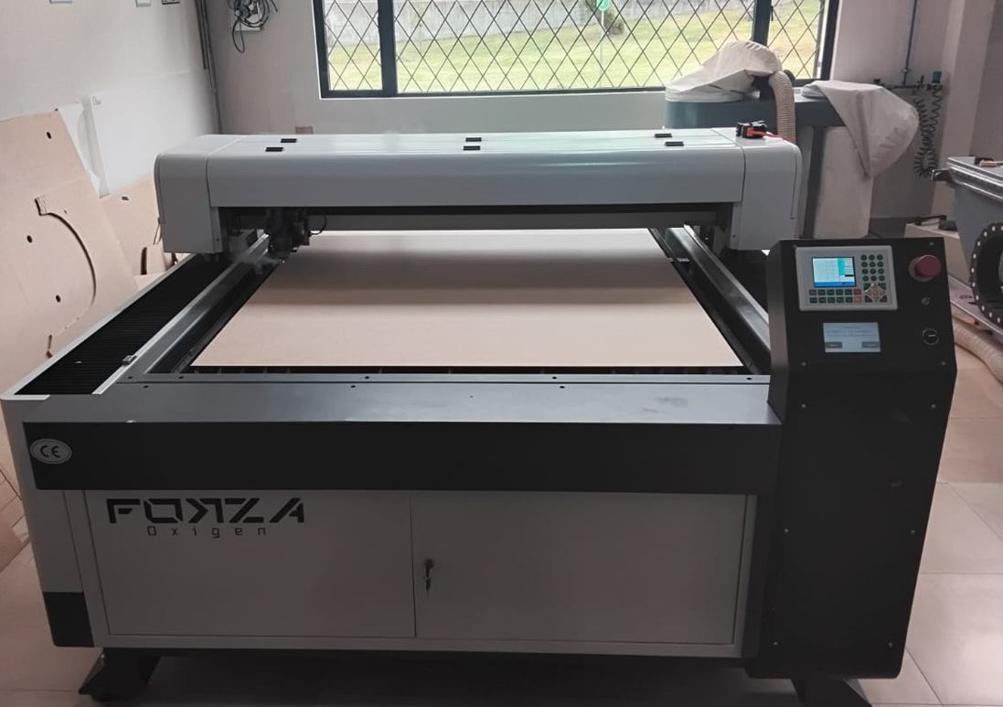
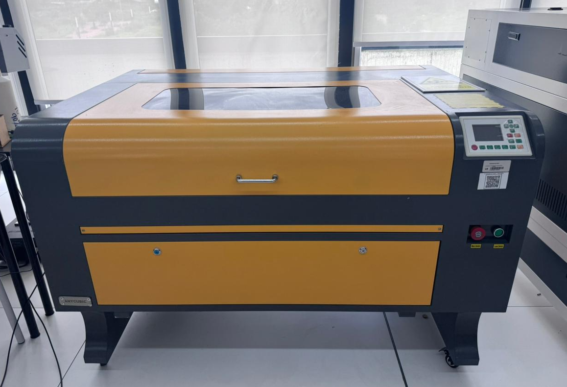
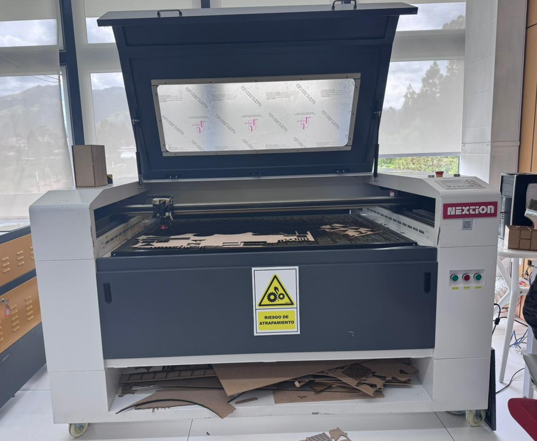
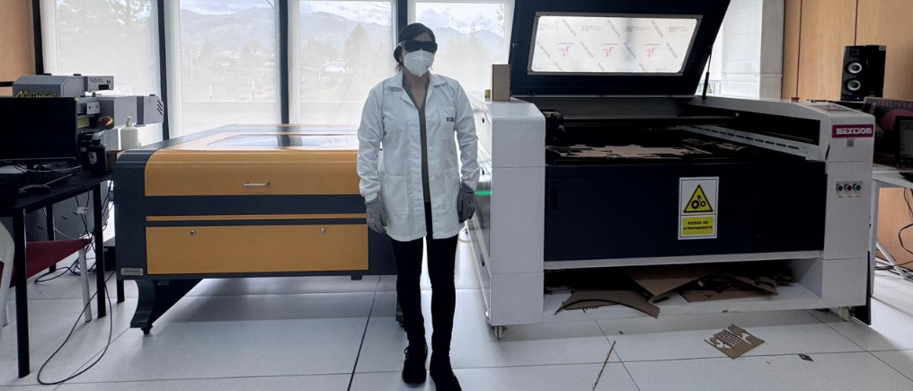
2. Available Laser Cutters
Across the participating labs, we documented four laser cutting machines. Two machines are available in our local lab, and two more were documented by our teammates. This allowed us to compare workflows, power ranges, machine formats, and typical cutting configurations.
3. Safety Protocol
Laser cutting requires both machine awareness and material awareness. The main risks are smoke generation, flare-ups, lens damage, hot material surfaces, and incorrect machine configuration. For that reason, the operator must follow a controlled startup routine and remain near the machine during the full cutting process.
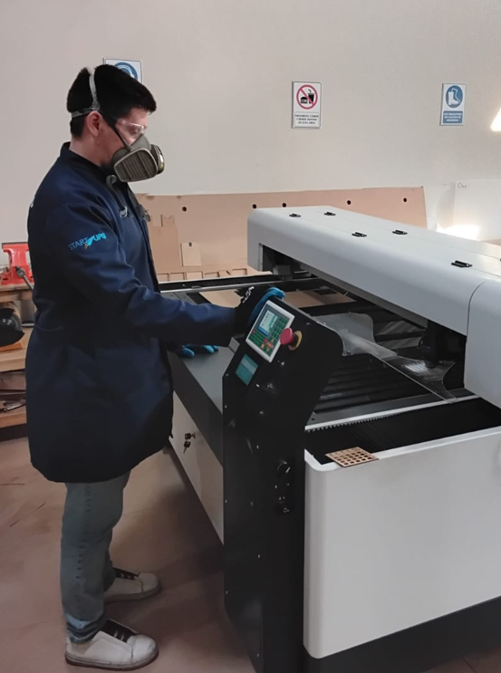
3.1 Personal Protective Equipment
- Protective glasses
- Mask, especially during handling of cut material and residue
- Apron or workshop protection clothing
3.2 Safe Machine Operation
- Do not place hands inside the machine while it is operating.
- Keep the extraction system turned on during all cutting and engraving processes.
- Keep the air assist on to reduce burning risk and protect optics.
- Verify that the chiller is active before enabling the laser.
- Do not leave the machine unattended while cutting.
- Check that the material is properly placed and flat on the bed.
- Always confirm the origin point and work area before sending the job.
3.3 Fire Prevention
- Air assist helps reduce local flame and prevents excessive heat concentration.
- Keep a suitable fire extinguisher nearby.
- A CO₂ extinguisher is recommended near electrical and laser equipment.
- An ABC extinguisher can also be kept as a general workshop backup.
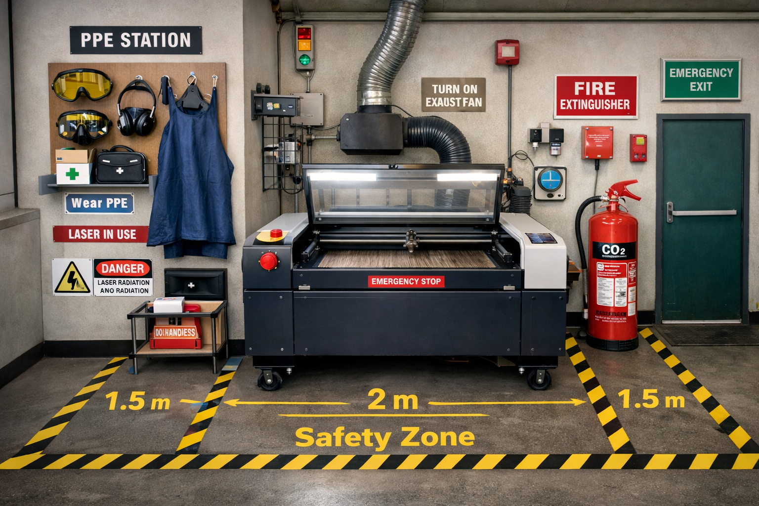
3.4 Recommended Clearance
As a practical workshop recommendation, it is useful to keep at least 1 meter of free space around the machine for safe movement, loading, maintenance, and emergency access. Larger industrial machines may require more clearance, especially in loading and unloading areas.
Some materials should not be cut in a standard CO₂ laser workflow. Unknown coated sheets, PVC, chlorine-based plastics, and questionable composite materials should be avoided because they can damage the machine and generate hazardous fumes.
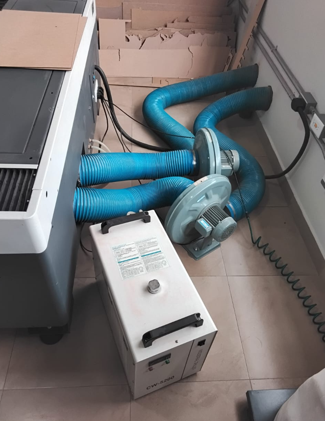
3.5 Ventilation and Extraction System
The extraction system is a critical component of the laser cutting workflow. It removes smoke, particles, and fumes generated during cutting and engraving, improving visibility and protecting both the operator and the machine.
- The extraction system must be turned on before any job starts.
- It reduces burning marks on the material surface.
- It protects lenses and internal components from residue buildup.
- It helps reduce fire risk during cutting operations.
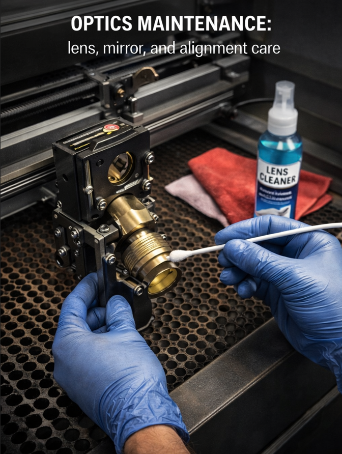
4. Preventive and Corrective Maintenance
Good machine maintenance has a direct effect on cutting quality, machine safety, and tube life. A laser cutter that is not cleaned and checked periodically will lose performance and become more prone to error.
| Maintenance Task | Type | Typical Frequency | Why it Matters |
|---|---|---|---|
| Lens cleaning | Preventive | Weekly or according to use | Maintains beam quality and reduces overheating risk. |
| Mirror cleaning | Preventive | Weekly or according to use | Improves beam alignment and power delivery. |
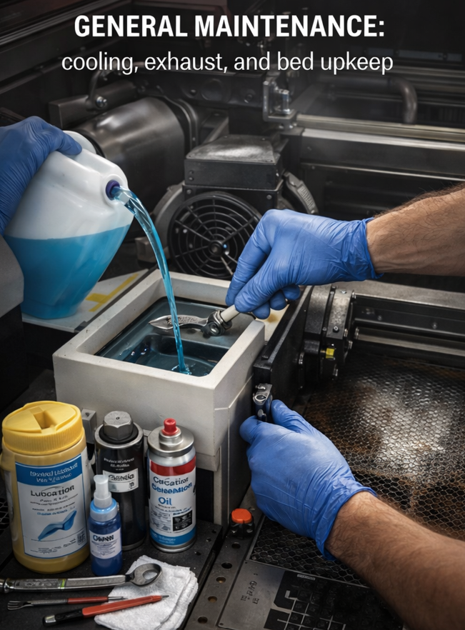
| Chiller water replacement | Preventive | Every 1–2 weeks or according to use | Protects the tube and prevents contamination of the cooling loop. |
| Extraction system cleaning | Preventive | Periodic | Improves smoke removal and keeps the work environment safer. |
| Guide lubrication | Preventive | Periodic | Maintains smooth motion and positional accuracy. |
| Bed cleaning | Preventive | After repeated use | Prevents residue buildup, staining, and poor support of materials. |
| Lens replacement | Corrective | When damaged or degraded | Necessary when cut quality decreases or the lens is burned. |
| Mirror replacement | Corrective | When damaged or degraded | Restores beam path quality. |
| CO₂ tube replacement | Corrective | When power drops significantly | Needed when the machine can no longer cut reliably at known good parameters. |
5. Machine Setup and Focus
Before cutting, the machine must be configured correctly. One of the most important steps is setting the focus height between the nozzle and the material surface. This is done using a reference spacer and adjusting the Z axis until the correct distance is reached.
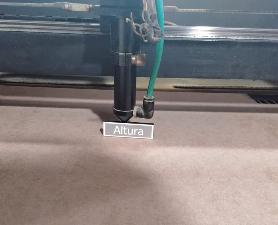
- If the head is too high, the beam loses focus and the cut becomes weak or incomplete.
- If the focus is incorrect, engraving can become blurry and vector cuts may develop slanted edges.
- The material origin must also be defined properly to avoid motion errors or jobs going outside the work area.
6. Material Comparison and Starting Parameters
The following table summarizes practical starting values for a 100W CO₂ laser system working with common materials. These values are useful as a reference and should always be fine-tuned according to machine condition, optics, focus, material brand, and desired finish.
| Material | Thickness | Operation | Speed | Power | Observation |
|---|---|---|---|---|---|
| MDF | 3 mm | Cut | 22 | 45 | Clean cut in a typical 100W setup. |
| MDF | 6 mm | Cut | 16 | 50 | Lower speed improves full cut penetration. |
| Acrylic | 3 mm | Cut | 22 | 45 | Good starting point for clear acrylic sheets. |
| Acrylic | 6 mm | Cut | 16 | 45 | Lower speed helps maintain cut continuity. |
| Cardstock | Thin sheet | Cut | 200 | 18 | Fast, low-power cut to reduce burning. |
| Cardboard | 2 mm | Cut | 150 | 20 | Useful for prototypes and packaging tests. |
| Plywood | 3 mm | Cut | 20 | 45 | May require cleanup depending on glue content. |
Recommended spacing between adjacent cut parts is at least 3 to 5 mm to reduce overheating, edge darkening, and local weakening between nearby vectors.
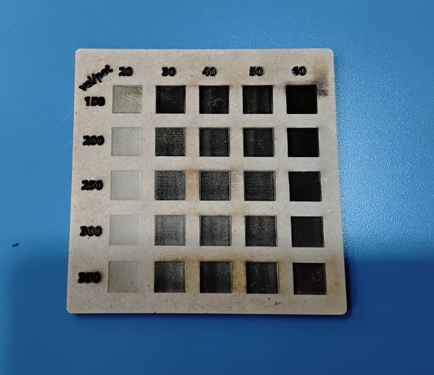
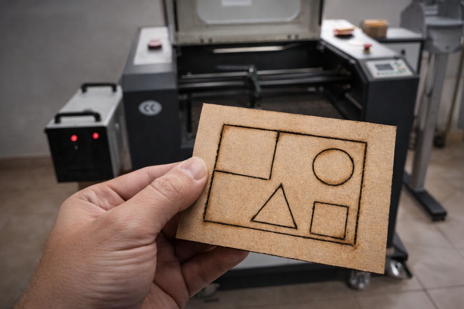
7. Engraving Parameter Tests
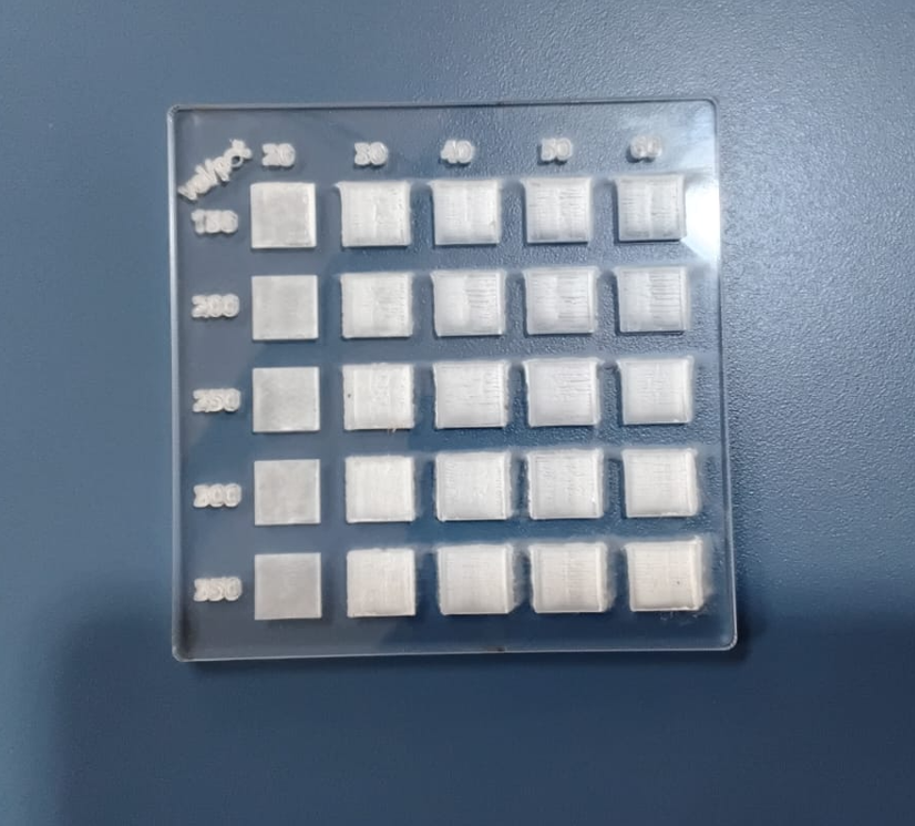
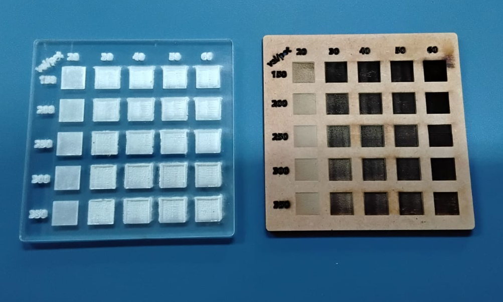
We tested engraving behavior by varying speed and power levels. In these trials, speed values ranged from 150 to 350 with steps of 50, while power values ranged from 20 to 60 with steps of 10. The goal was to observe depth, contrast, surface damage, and heat effects in MDF and acrylic.
| Material | Speed | Power | Assessment |
|---|---|---|---|
| MDF | 350 | 30 | Good controlled engraving with acceptable burn level. |
| MDF | 350 | 40 | Deeper mark, still acceptable and visually clear. |
| Acrylic | 350 | 20 | Best tested acrylic engraving among the evaluated settings. |
In MDF, low speed combined with high power such as 60 can produce excessive burning and very deep marks, which may not be visually desirable. Acrylic also reacts strongly to power concentration, so moderate settings are preferable for a cleaner result.
8. Kerf Test
Kerf is one of the most relevant values for press-fit construction. To characterize it, we designed a fitting test, cut the pieces, and checked which slot width produced a smooth pressure fit without force and without looseness.
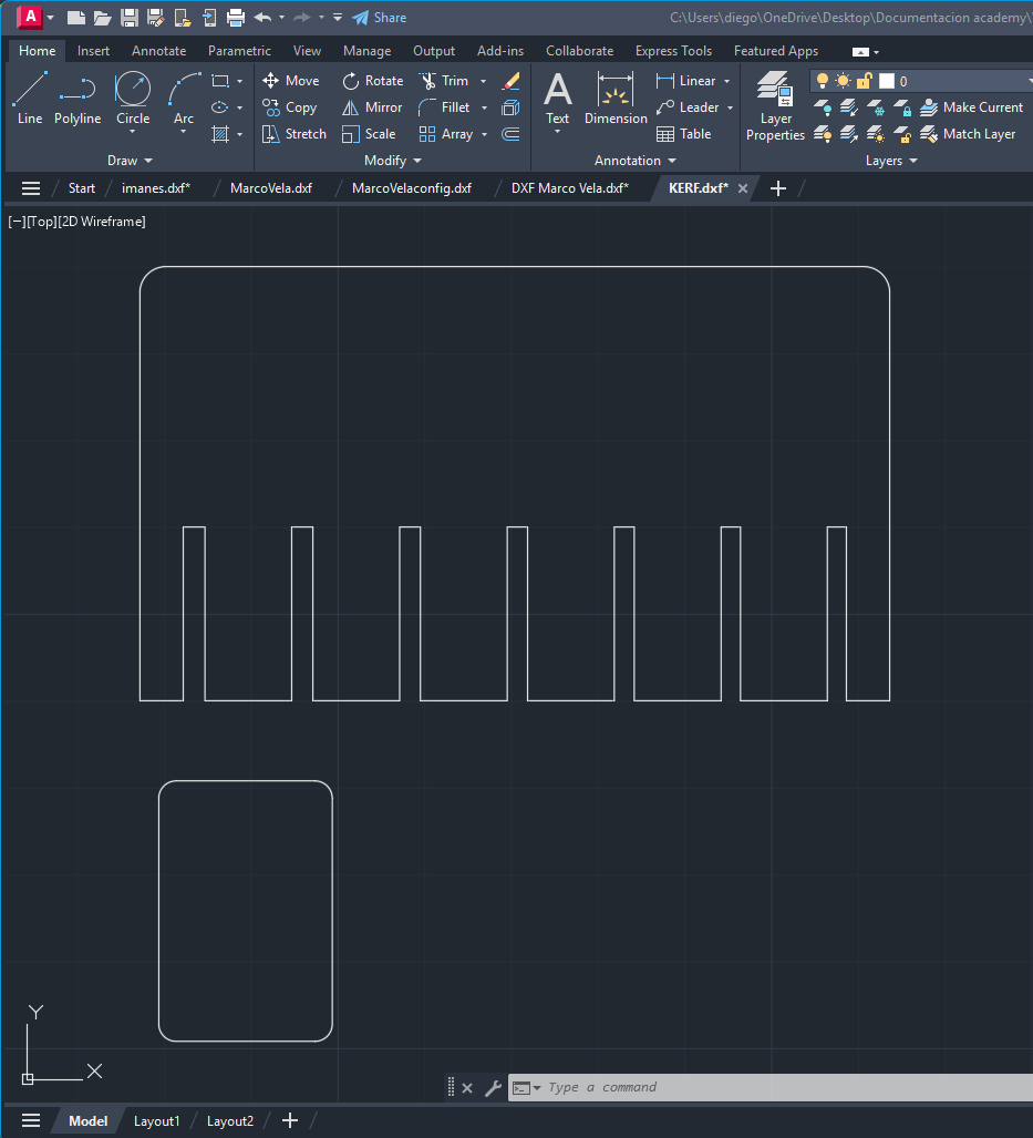
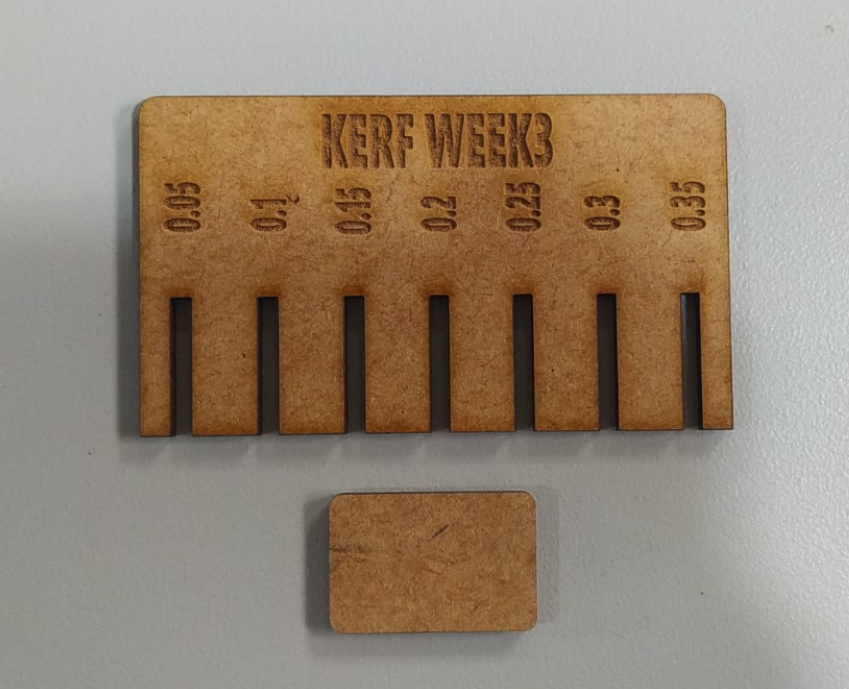
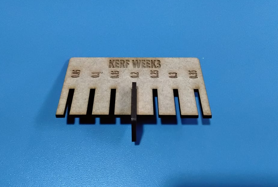
This kerf value was then used as the reference for press-fit slot adjustment in the individual parametric design workflow.
9. Common Errors and Troubleshooting
During laser cutting, several setup errors can prevent correct cutting or engraving. Documenting these issues is useful because many failures are not caused by the design itself, but by machine preparation or job setup.
- Chiller off: the laser will not fire correctly, so the machine will not cut.
- Air assist off: increases the risk of burning the lens and igniting the material.
- Incorrect height calibration: the beam defocuses, cutting weakens, and engraving becomes less defined.
- Too much focus height: may cause a slight beam spread and produce slanted or poor-quality cuts.
- Origin not defined correctly: the machine may attempt to move outside the cutting area and generate axis errors.
- Scan placed too far on the X limit: may generate a displacement error because of machine travel constraints.
- Dirty lens or mirrors: reduces power delivery and lowers cut quality.
- Material not flat: changes local focus and causes inconsistent cutting depth.
10. Cross-Lab Notes
A useful part of this group exercise was comparing the information documented across different students and machine contexts. Even when the machines are not identical, the same logic appears repeatedly: machine setup, focus, material thickness, kerf adjustment, and safe operation are the factors that most strongly affect the final result.
- Kerf compensation is essential when designing press-fit systems.
- Focus calibration is one of the fastest ways to improve cut quality.
- Air assist and extraction are not optional; they directly affect safety and finish quality.
- Reference starting values are useful, but each machine still requires local adjustment.
11. Conclusions
- Laser cutter characterization is necessary before making press-fit designs or detailed engraving work.
- Safety depends not only on PPE, but also on machine preparation, extraction, air assist, and supervised operation.
- Kerf testing is fundamental for dimensional accuracy and assembly behavior.
- Focus calibration strongly affects both engraving sharpness and vector cut quality.
- Moderate engraving values gave the best visual results in MDF and acrylic, while high power and low speed tended to overburn the material.
- Preventive maintenance of optics, cooling, extraction, and guides directly improves reliability and output quality.
- Reference parameter tables are useful starting points, but each machine and material combination still requires validation.
- Cross-lab comparison helped confirm that machine behavior changes in scale and format, but the core design rules remain consistent.