NODO

Parametric Design, Kerf Calibration and Press-Fit Assembly
For the group assignment, the lab characterized the laser cutter by analyzing key parameters such as focus, power, speed, kerf, and material behavior. This collaborative work allowed us to understand how different configurations affect cutting quality and precision.
The results obtained from this characterization directly supported the individual development of the press-fit construction kit presented on this page, ensuring proper tolerances and accurate assembly.
Open Group AssignmentAs part of the Fab Academy Week 3 assignment, I designed and fabricated a parametric construction kit focused on press-fit assembly. For the parametric modeling process, I used Fusion 360 as the main CAD software.
As a construction reference, I based the design on the assembly logic of a pre-designed piece of furniture developed in Rhinoceros with Grasshopper, which can be reviewed in Assignment 02.
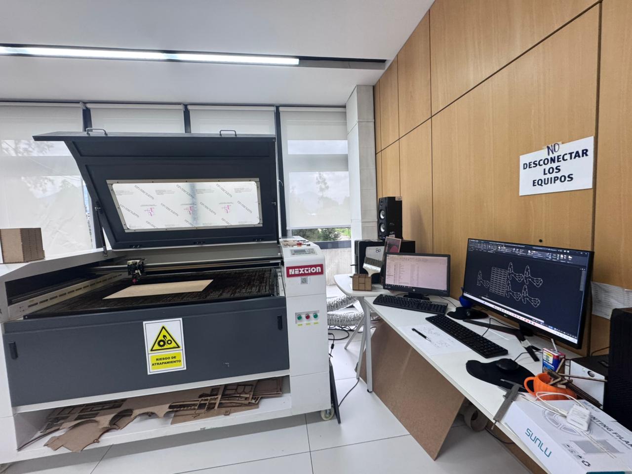
The fabrication process was carried out using a 90 W CO₂ Core Laser cutting machine available at the Industrial FABLAB. The main objective of this exercise was to achieve a fully functional press-fit system without the use of adhesives, relying entirely on parametric control and kerf calibration.
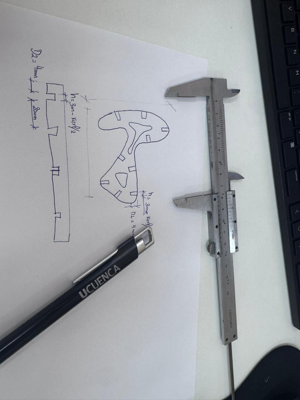
The design process started from a construction plan using curvilinear tracing. Initially, the geometry was explored through hand sketches on paper, defining the shape, proportions, and dimensions of the assembly links before moving into the digital environment.
This step was essential to understand how the individual parts would interact mechanically during assembly and to establish the initial measurements of the press-fit joints.
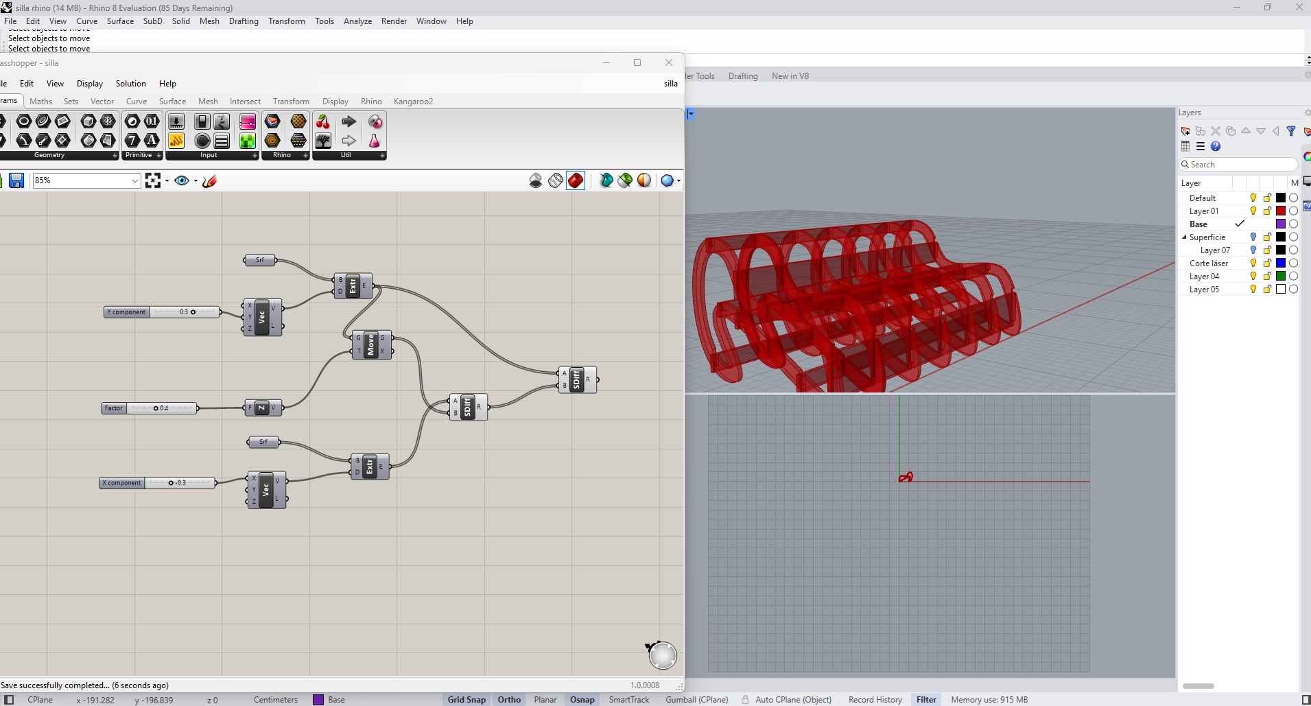
Image c001
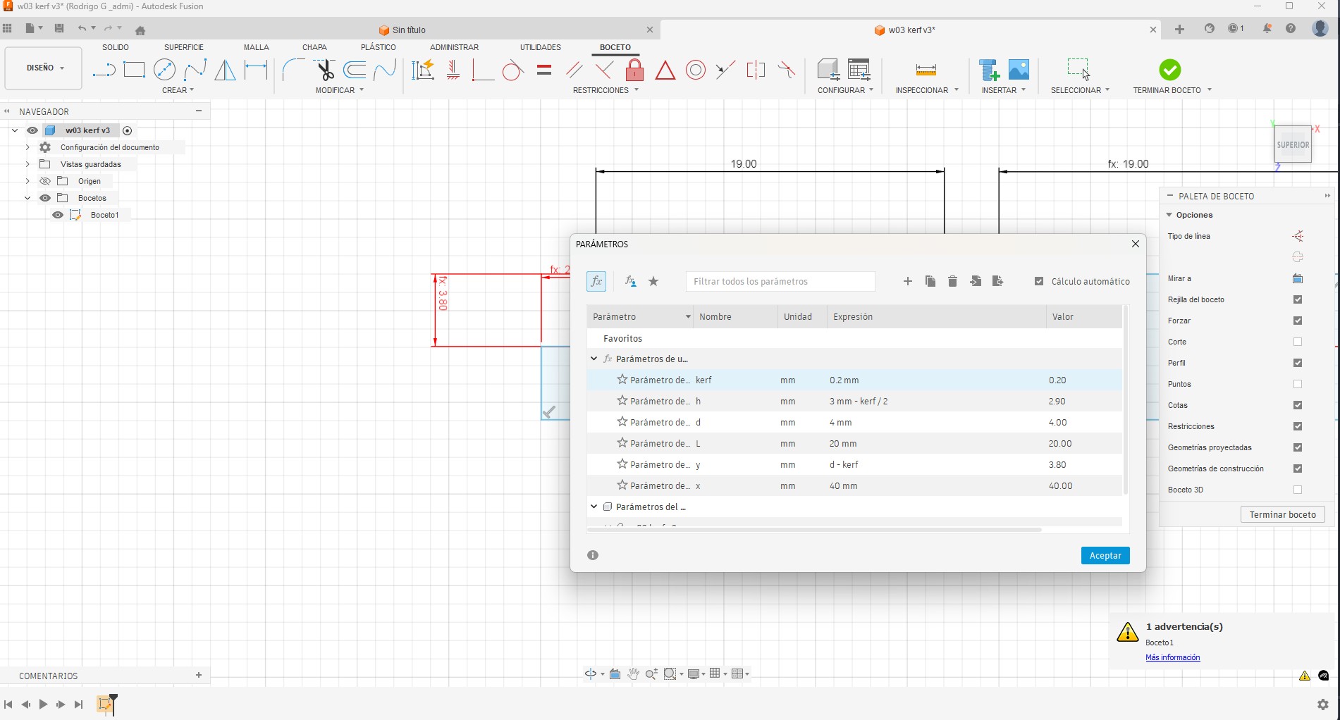
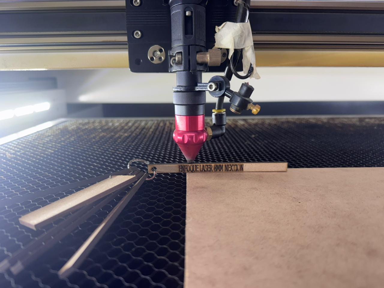
To ensure a precise press-fit assembly, the kerf value of the laser cutting machine was calculated. This was done using a reference table that combines laser power (in watts) and cutting speed (in mm/s).
The best cutting result was obtained using a combination of 40 W power and 40 mm/s speed, which produced a measured kerf of 0.05 mm.
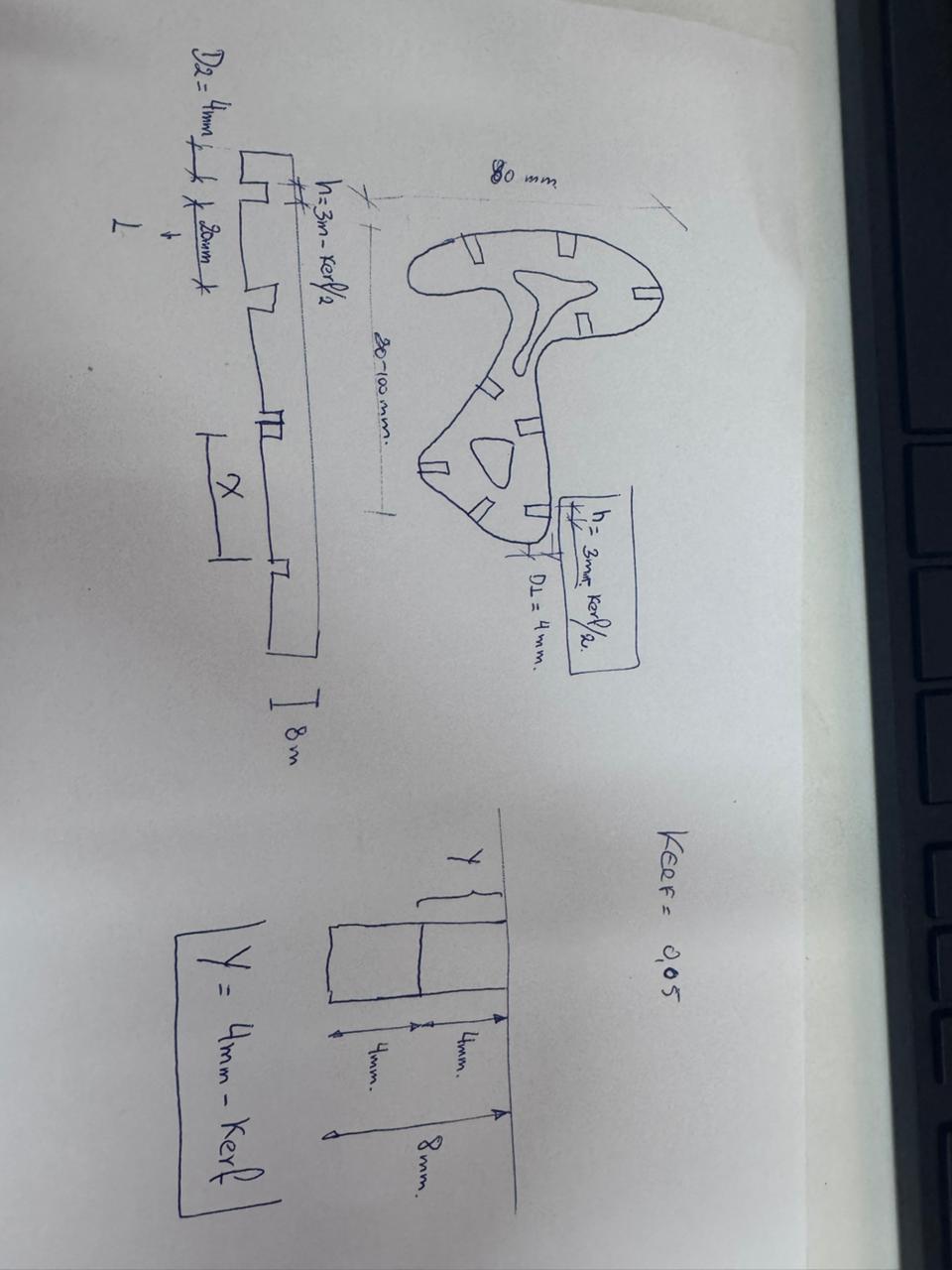
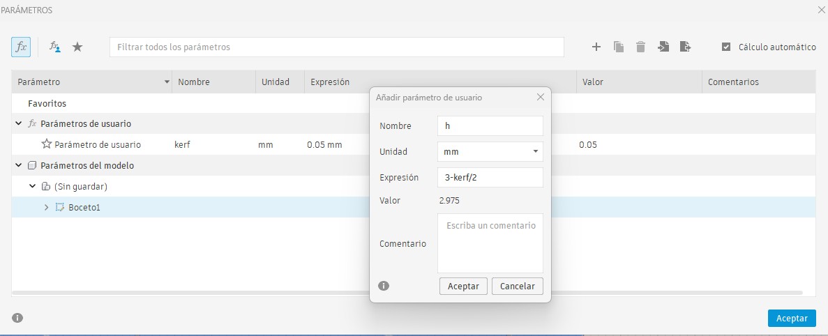
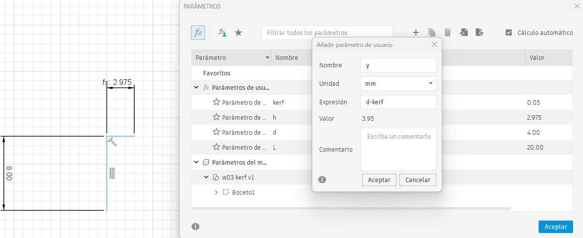
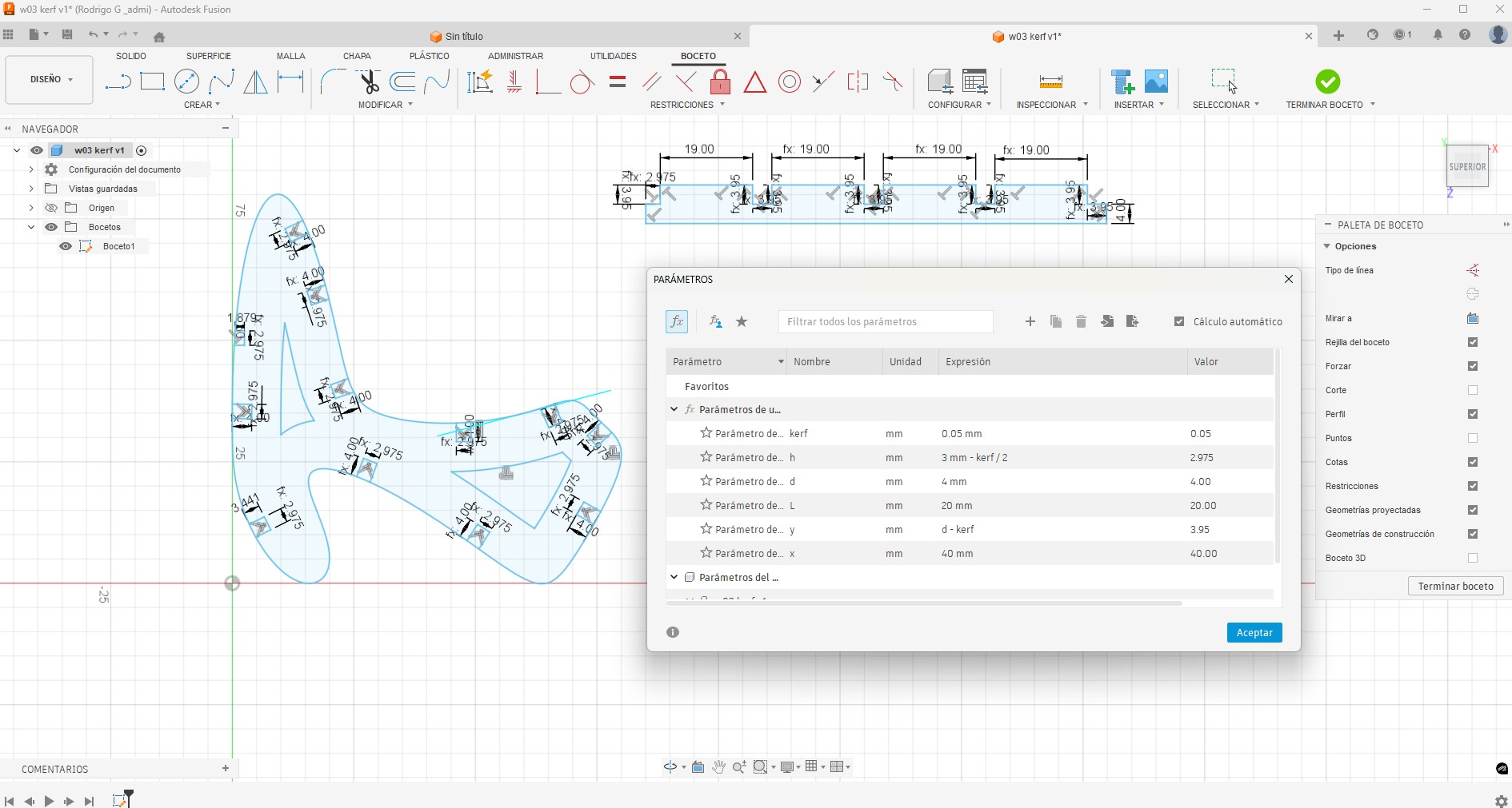
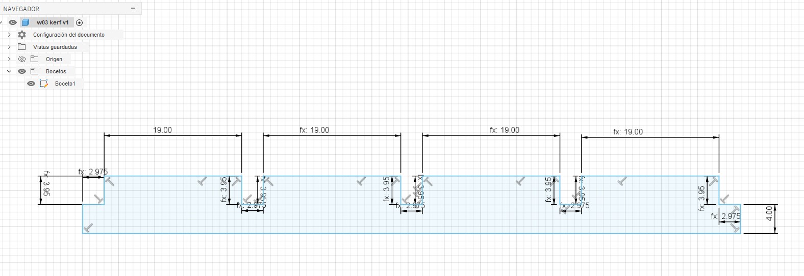
Once the kerf value was established, the design was fully parameterized in Fusion 360 using the following variables:
The chair was designed within a working area of 80 × 80 mm, allowing a compact yet functional prototype.
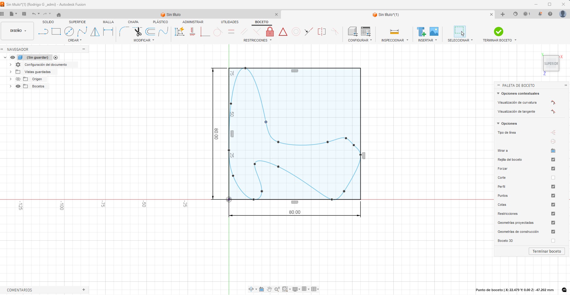
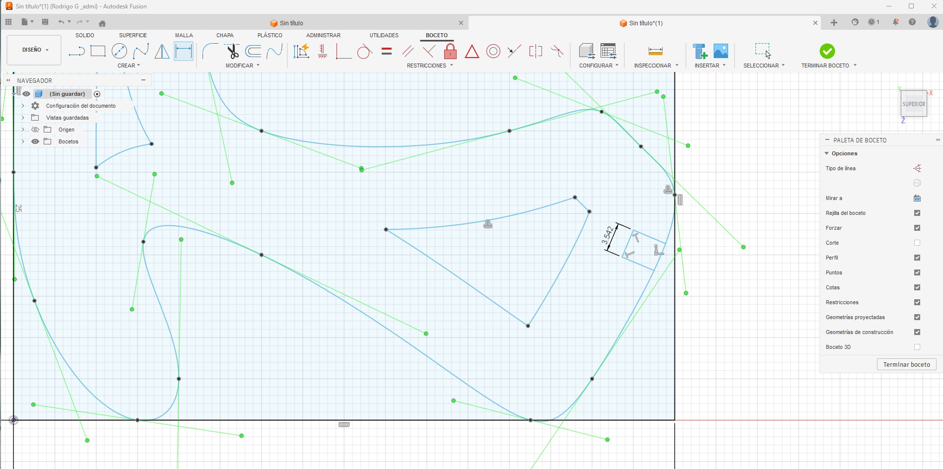
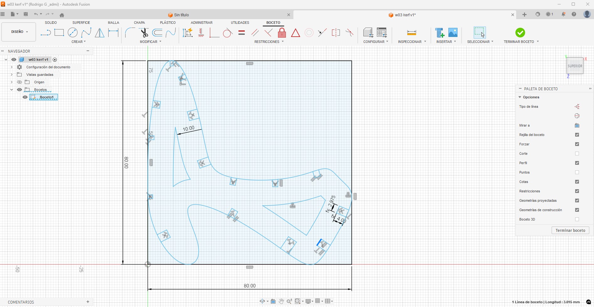
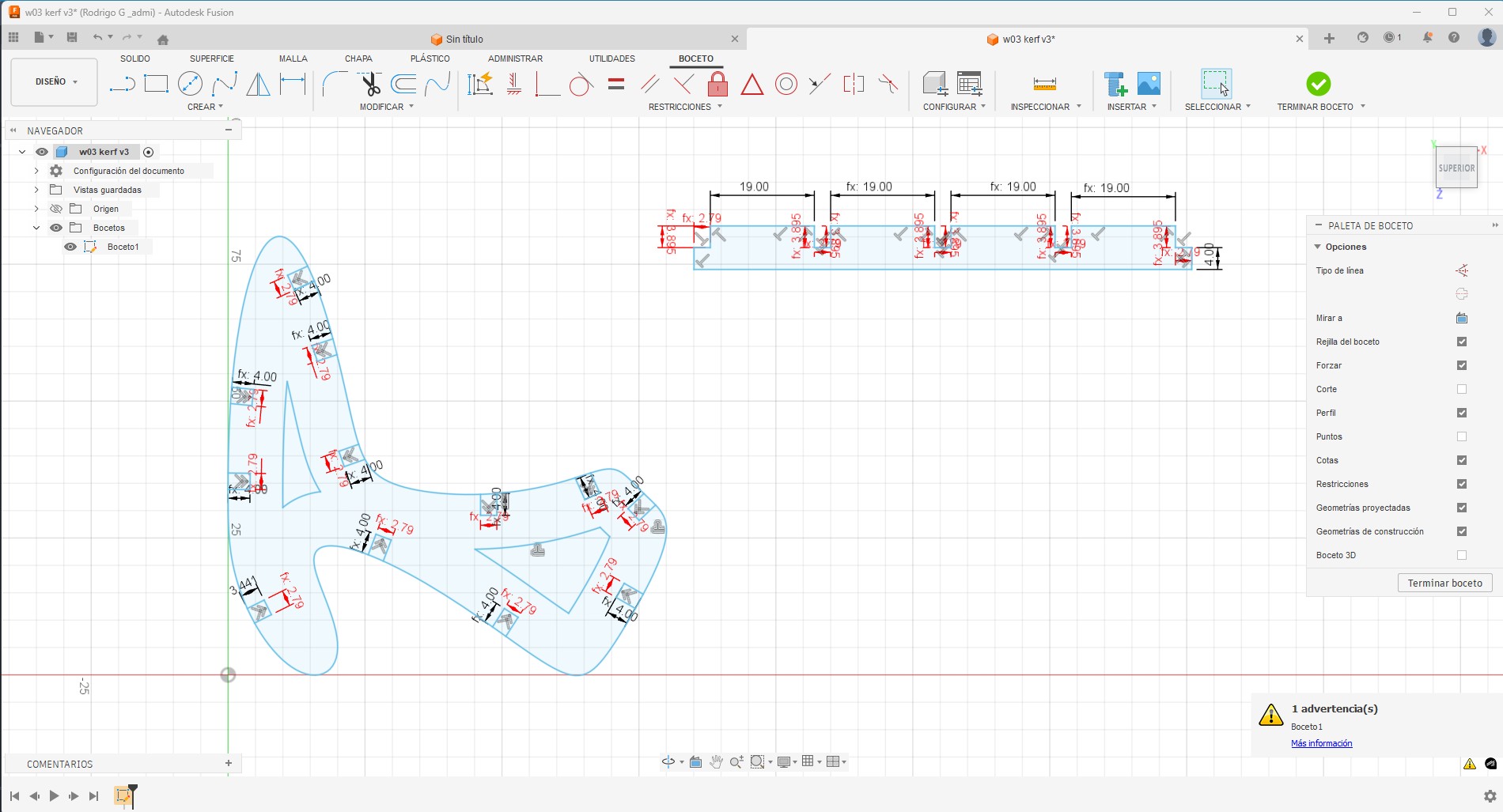
After defining the main geometry, the notches and joints were drawn directly on the construction plane. All joints were designed using parametric values, allowing easy adaptation if a different material, thickness, or kerf value were required.
This approach ensures that the design remains flexible and scalable, which is a key principle in digital fabrication workflows promoted by Fab Academy.
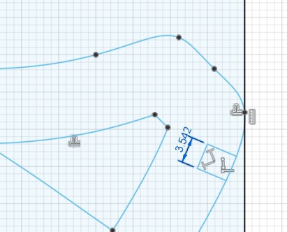
All notches were referenced sequentially using the defined parameters and tolerances. Once the main chair structure was completed, the crossbars (travesaños) were designed using the same parametric logic to ensure consistency throughout the assembly.
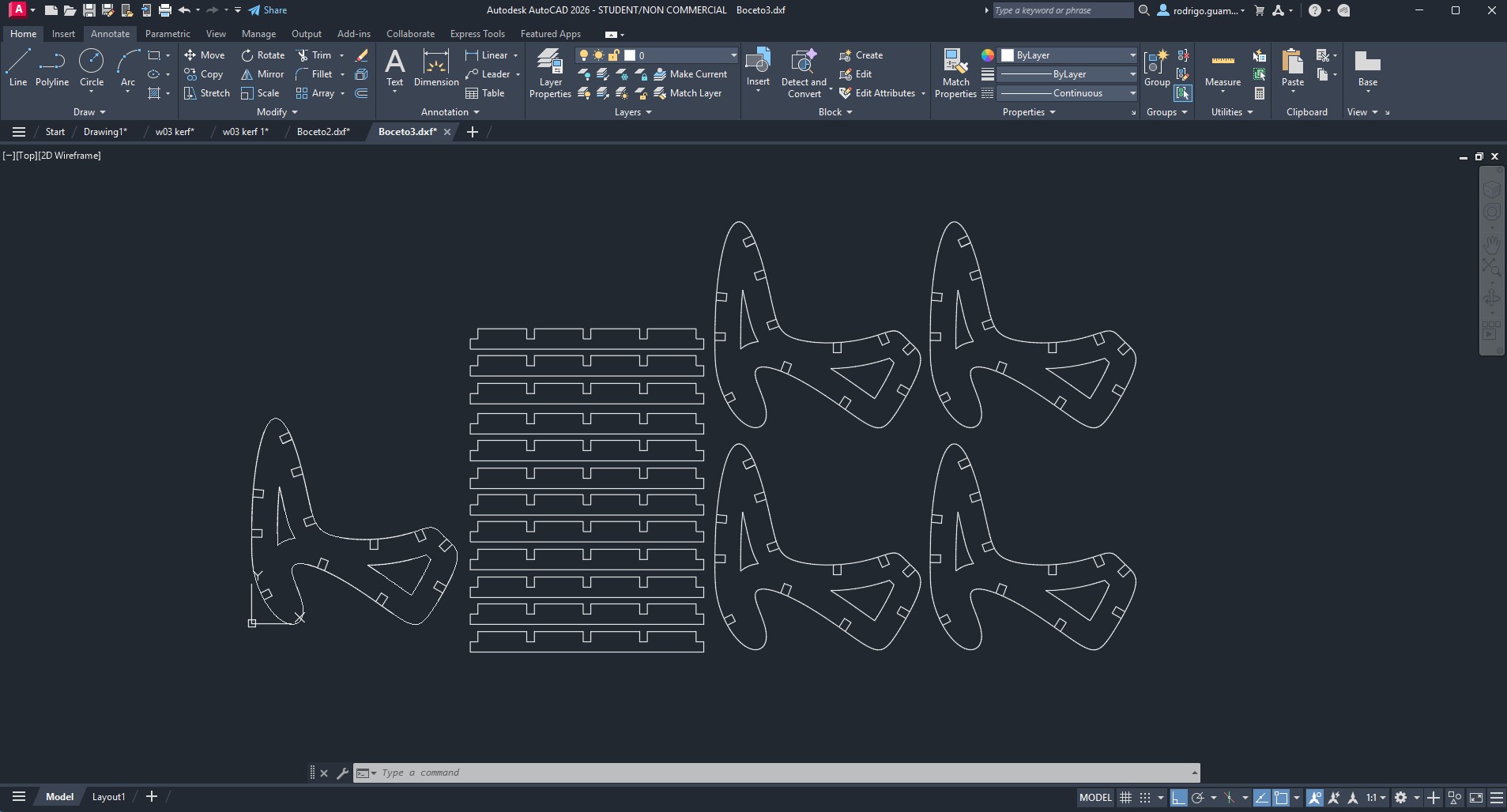
As an additional workflow, AutoCAD was used to duplicate the chair components and crossbars, organizing them efficiently on the cutting layout. The files were exported in DXF format and sent to the laser cutting machine for the first physical test.
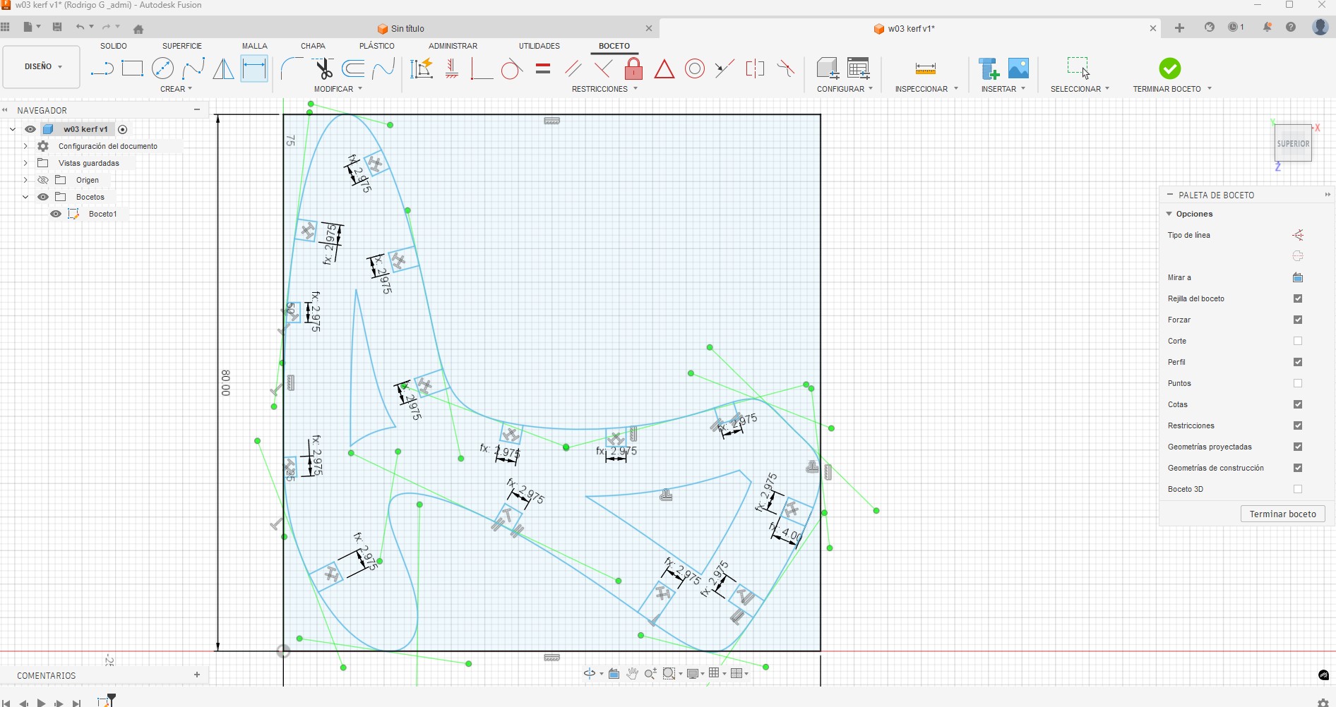
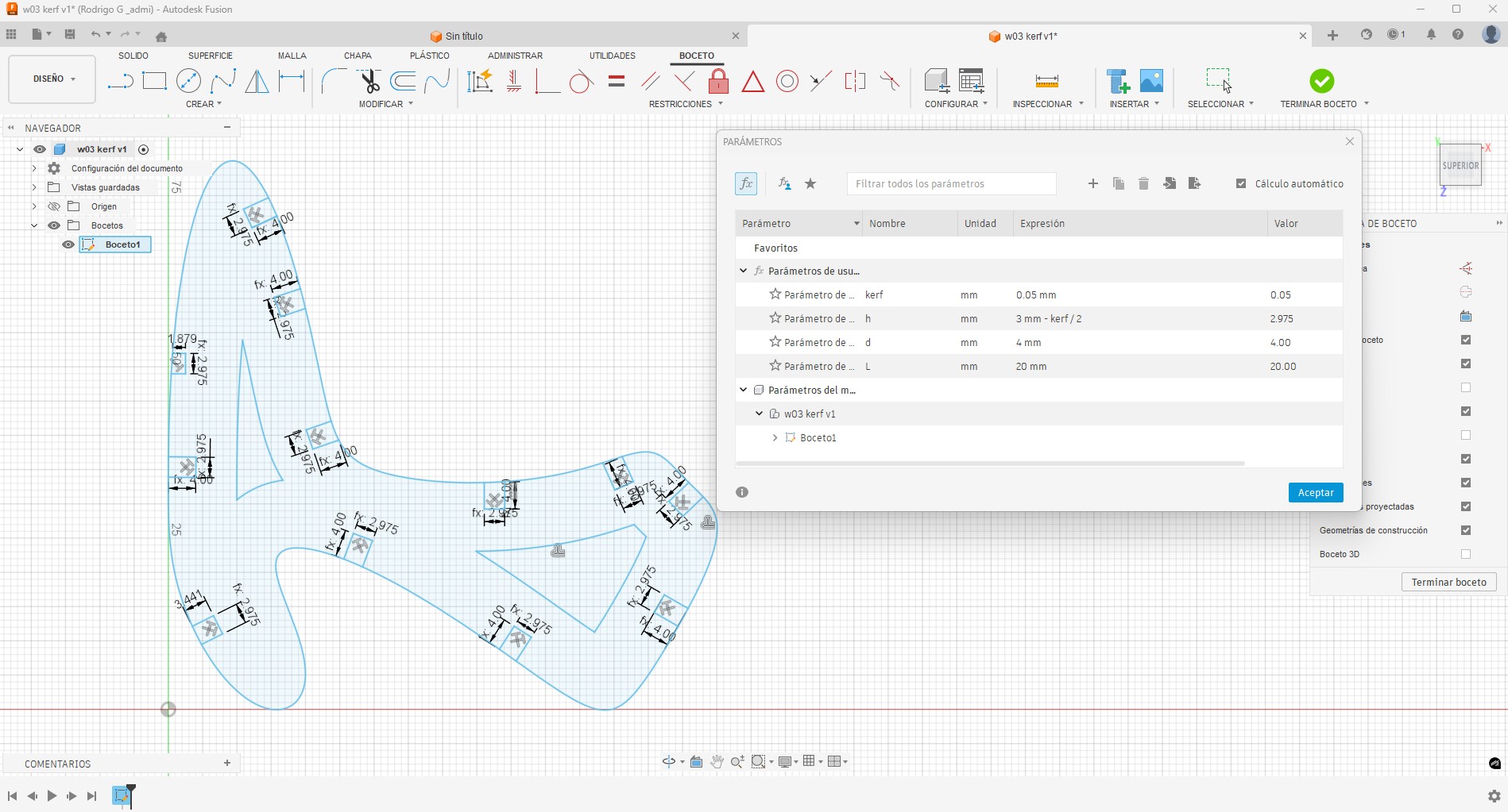
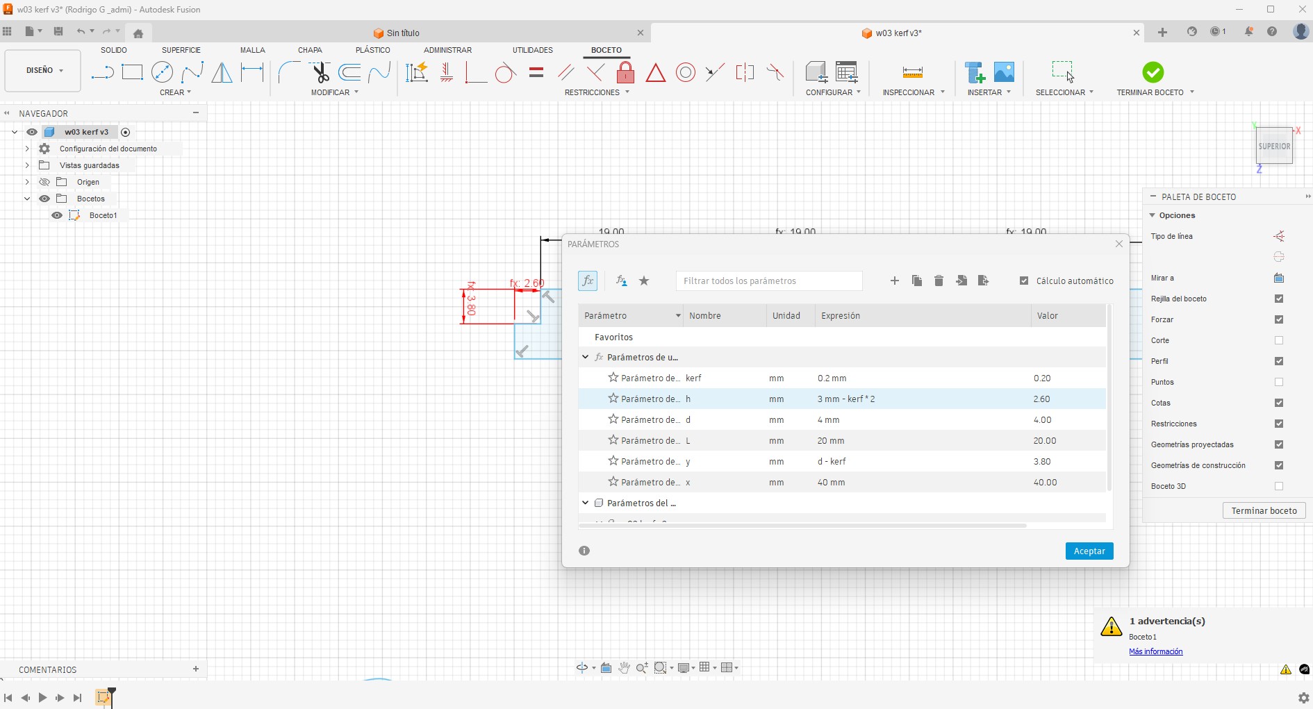
During the first iteration, excessive looseness was observed in the joints.
To correct this, the kerf-related parameters were adjusted, increasing the
joint tightness while maintaining the original kerf value.
The updated parameters were:
The process begins with the parametric design, which allows precise control over dimensions and tolerances. Based on this, the machine is prepared considering the kerf (material removed during cutting). A kerf value of 0.05 mm is established, and machine parameters such as power and speed are calibrated to ensure accurate cuts without affecting the fit between parts.
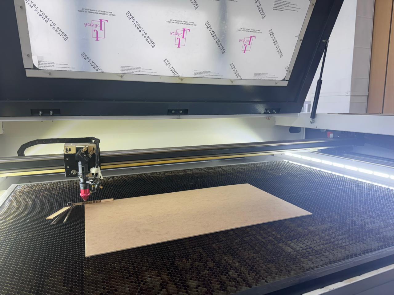
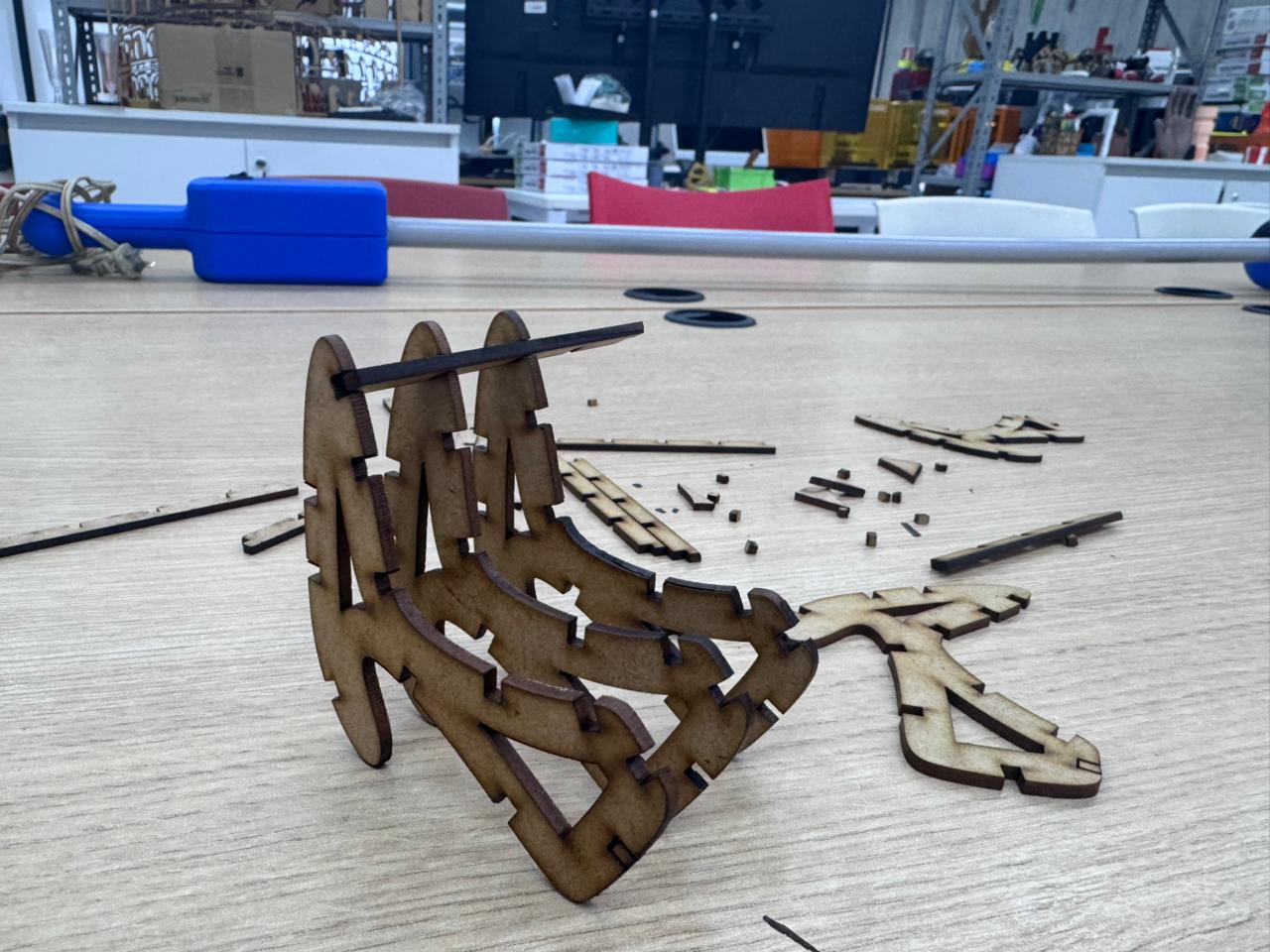
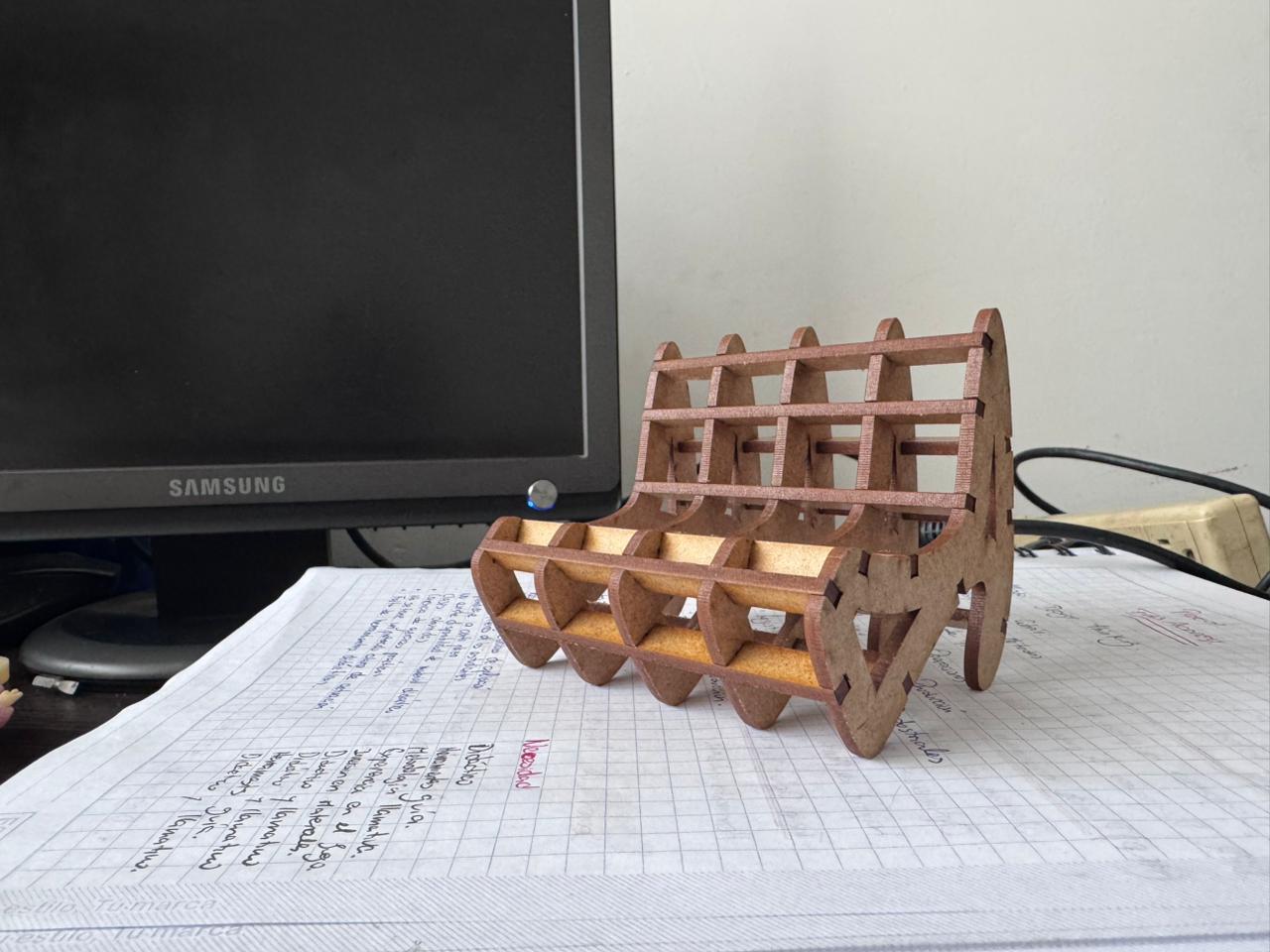
After recalibrating the parameters and adjusting the laser focus height, the final parts were fabricated. The assembly process was carried out manually, verifying the press-fit behavior of each joint.
Next, the cutting profiles are developed using AutoCAD, where all components are defined according to the parametric design. This includes adjusting dimensions with the kerf value and organizing the correct number of pieces required for fabrication, ensuring efficiency and precision in the cutting layout.
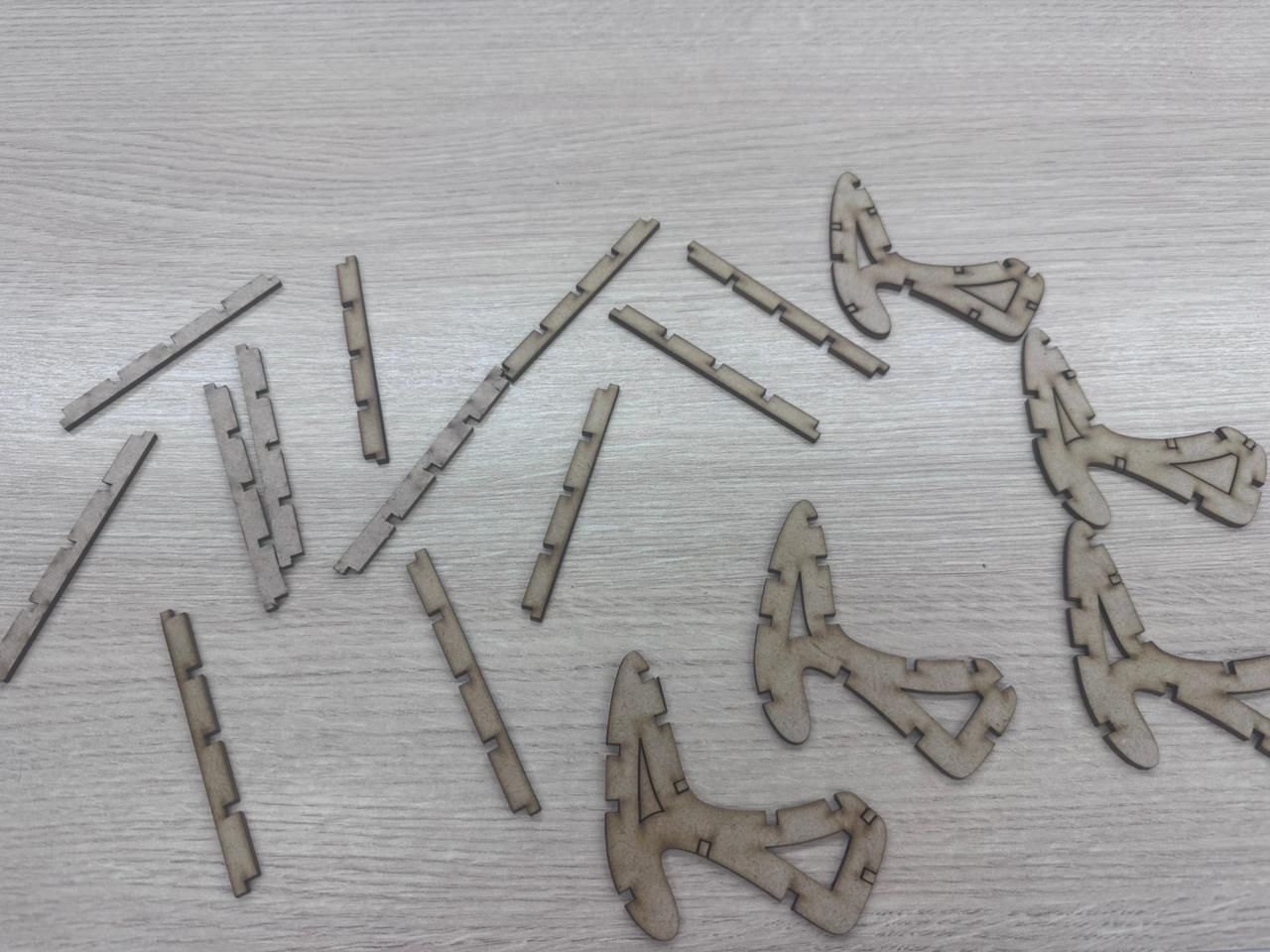
Once the design is finalized, the cutting process is carried out. After fabrication, all pieces are carefully classified and organized prior to assembly. It is important to highlight that the structure consists of 13 cross members and 5 main profiles, which together form the final chair structure according to the original design.
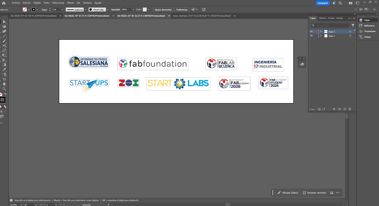
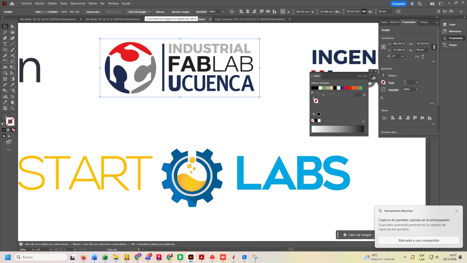
As part of this weekly assignment, we focused on the design and fabrication of custom logos using vinyl cutting techniques. The objective was to create and produce representative logos for each team and lab: Starlabs from Universidad Politécnica Salesiana, Industrial FABLAB from Universidad de Cuenca, and ZOILAB.
This activity allowed us to apply subtractive manufacturing processes on flexible materials such as adhesive vinyl, combining digital design with physical production.
Each logo was designed in vector format using CAD software, ensuring all elements were properly defined as clean paths. Since vinyl cutting requires vector geometry, special attention was given to eliminating duplicate lines and ensuring closed contours. The final designs were exported in compatible formats such as SVG or DXF.
The design was sent to the vinyl cutter, where the blade precisely followed the vector paths. Care was taken to ensure the cutting depth was sufficient to cut the vinyl layer without damaging the backing material.
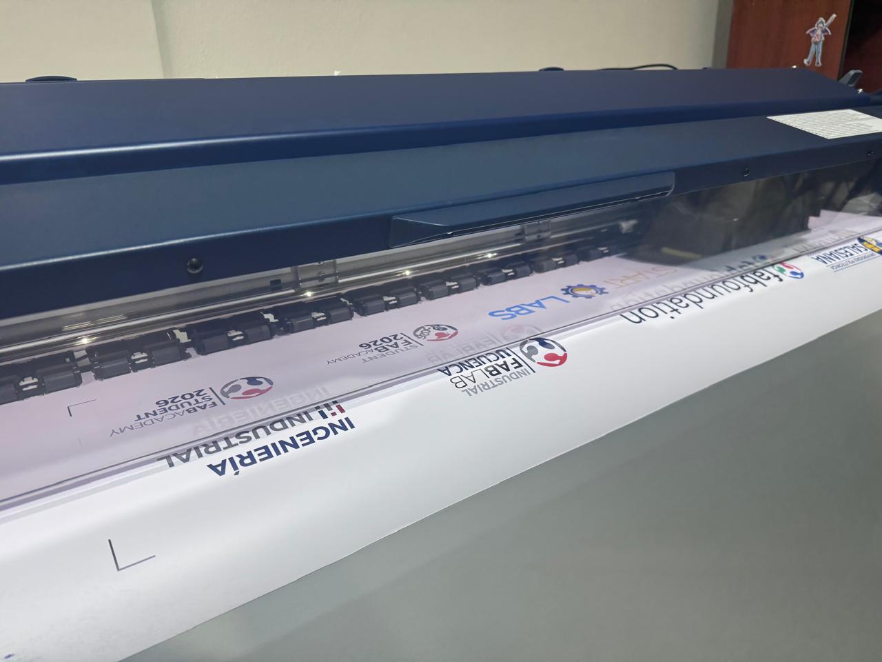
After cutting, the excess vinyl was removed manually in a process called weeding. This step requires precision to avoid lifting small or detailed parts of the design.
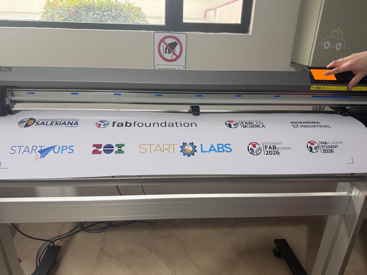
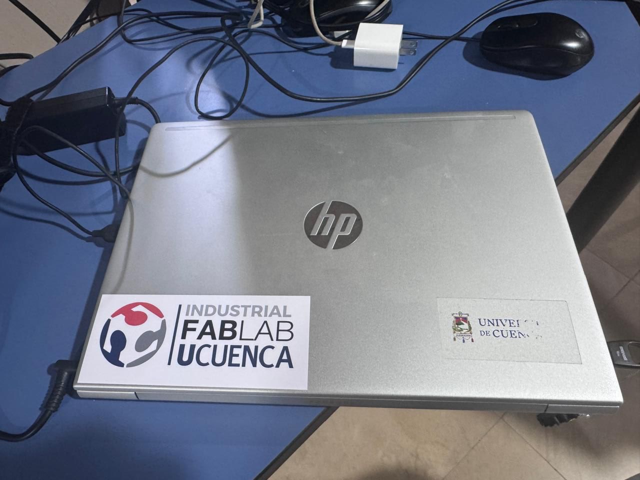
Transfer tape was applied over the design to facilitate placement. The vinyl was then transferred onto the desired surface, ensuring proper alignment and adhesion.
This assignment demonstrates the workflow from digital design to physical output using a vinyl cutter, highlighting precision, material handling, and finishing techniques.
This assignment highlighted the critical role of parametric design in digital fabrication, particularly when working with press-fit systems. Accurate kerf calibration and iterative testing proved essential to achieving a reliable assembly without adhesives.
The integration of Fusion 360, Rhino + Grasshopper references, AutoCAD, and laser cutting workflows reflects the Fab Academy methodology of linking design, experimentation, and manufacturing.
This exercise strengthened my understanding of parametric control, tolerance management, and iterative prototyping, skills that will be directly applied in the development of my final project.