Week 03
Computer-Controlled Cutting
Parametric Design, Laser Cutting, Kerf Testing, Press-Fit Construction Kit, and Vinyl Cutting
1. Checklist
- ✅ Linked to the group assignment page
- ✅ Reflected on my individual page what I learned from the lab safety training
- ✅ Explained how I created my parametric design
- ✅ Documented how I made my press-fit construction kit
- ✅ Documented how I made something with the vinyl cutter
- ✅ Included my original design files
- ✅ Included hero shots of my results
2. Group Assignment
For the group assignment, the lab characterized the laser cutter and documented key parameters such as focus, power, speed, kerf, and material behavior. That group documentation supports the individual development of the press-fit construction kit shown on this page.
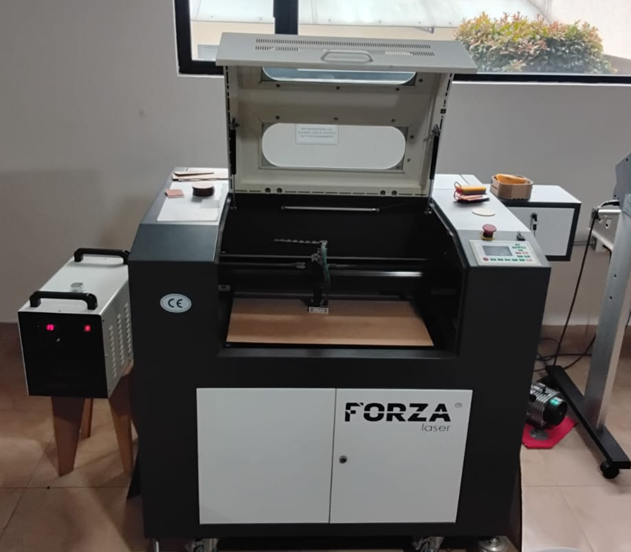
3. Laser Cutter Used
For this assignment I used a 100W CO₂ laser cutter. The machine includes an extraction system to remove smoke during the cutting process and a chiller that circulates distilled water to keep the laser tube in safe working conditions. The available work area is 60 cm × 40 cm, which is enough for cutting MDF and acrylic sheets used in this project.
4. Safety and Workflow Considerations
One important part of this week was understanding that computer-controlled cutting is not only about design and fabrication, but also about machine safety and material handling. During the laser cutting workflow, I considered the machine status before each job, checked the extraction system, verified the chiller operation, and kept the process supervised while cutting.
- The emergency stop must always be accessible before starting the cut.
- The extraction system must be active to remove smoke and fumes.
- The chiller must be working correctly to protect the laser tube.
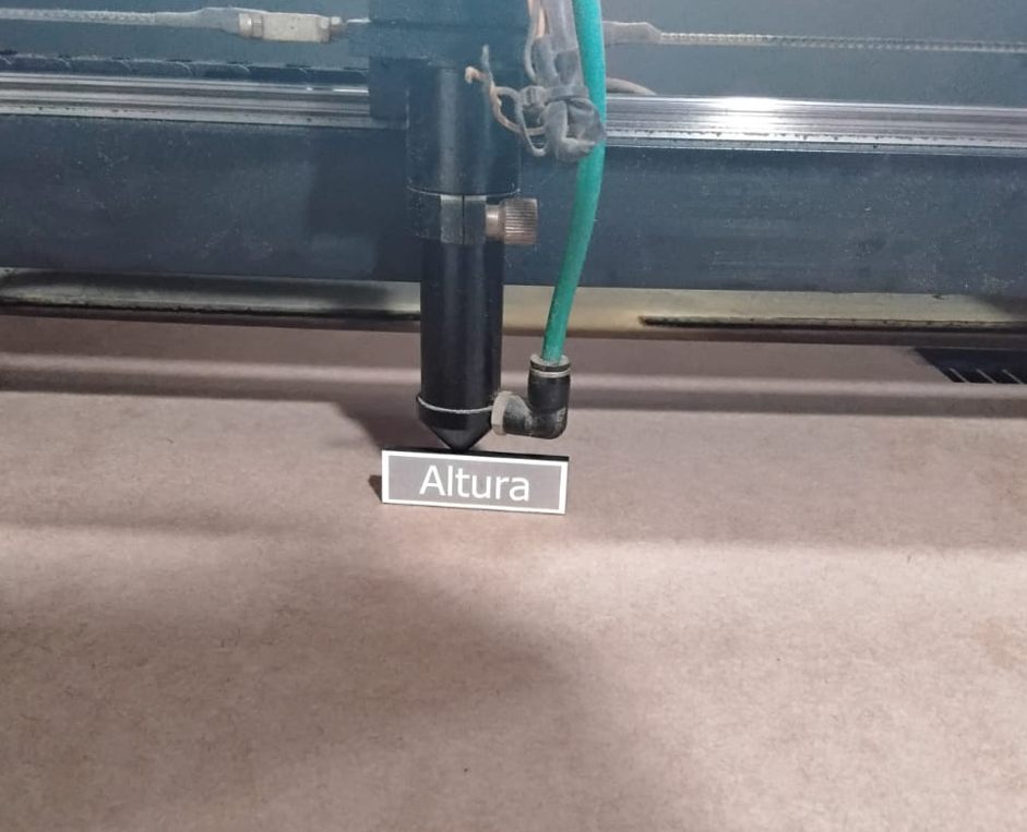
- The material must be placed flat on the bed before focusing the head.
- The cut must not be left unattended while the machine is operating.
- Only suitable materials should be cut in the laser cutter.
- For vinyl work, correct media loading and cut alignment are also part of a safe workflow.
This safety reflection became part of my fabrication routine, especially during focusing, sending files, supervising the cut, and handling the final pieces.
5. Material Measurement and Kerf Test
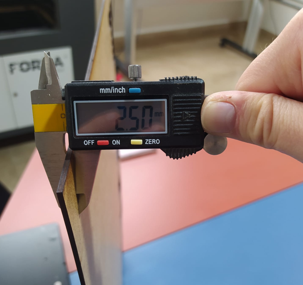
Before defining the final slot size for the press-fit kit, I first measured the real thickness of the available MDF sheet. This is important because the nominal thickness is not always equal to the actual material value. After that, I prepared a kerf test to determine the exact fit that would allow the parts to connect smoothly without forcing the assembly and without leaving them loose.
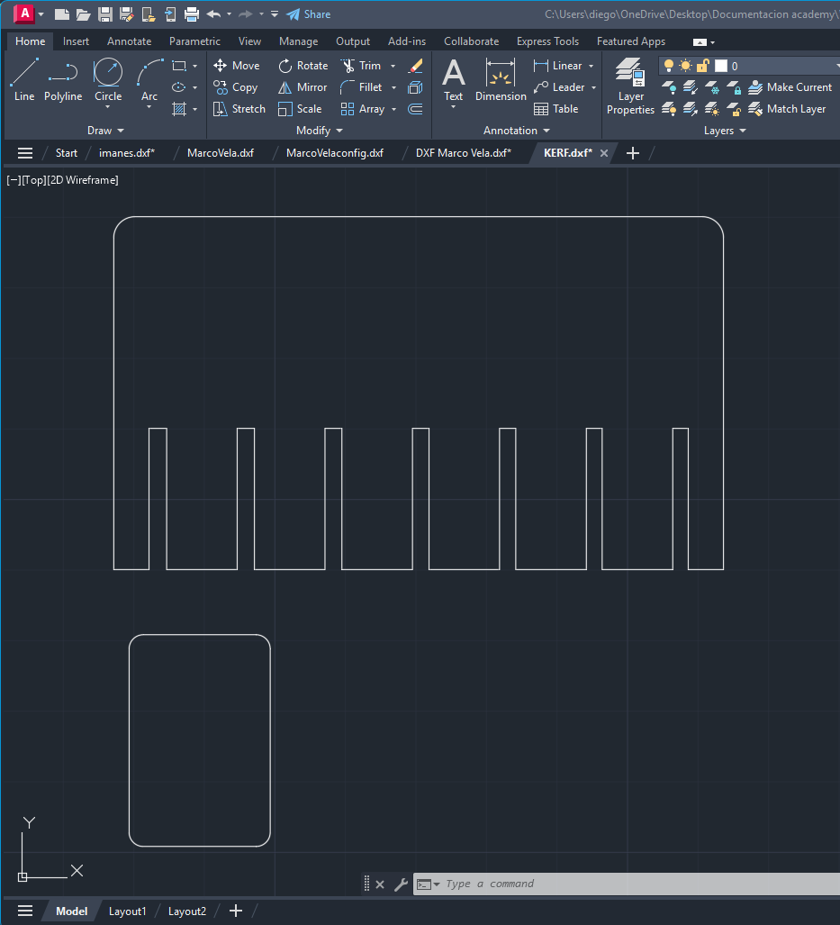
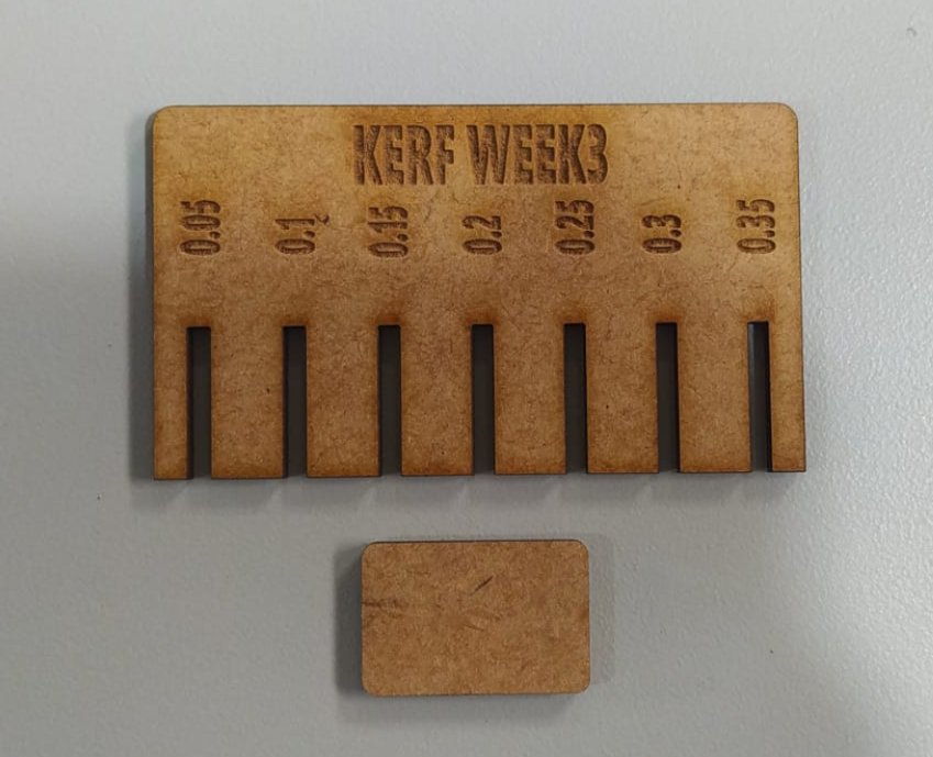
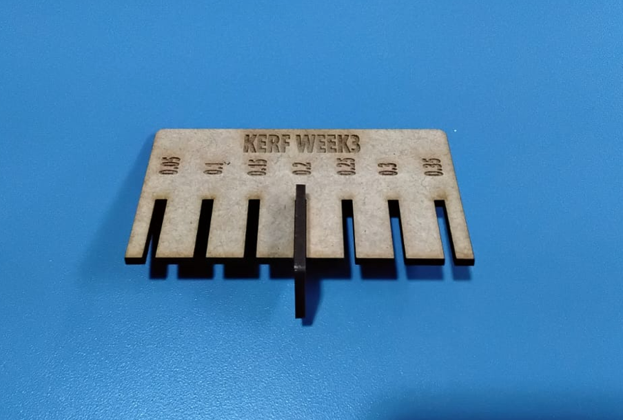
To make the kerf selection systematic, I tested a sequence of slot tolerances from 0.05 mm to 0.35 mm relative to the measured material thickness. Each slot increased by 0.05 mm, producing a total of 7 test slots. This comparison allowed me to evaluate which value gave the best mechanical behavior during insertion.
| Test slot | Tolerance / kerf offset | Observation |
|---|---|---|
| 1 | 0.05 mm | Very tight fit, excessive insertion force. |
| 2 | 0.10 mm | Tight fit, still difficult to insert. |
| 3 | 0.15 mm | Improved behavior, but still slightly tight. |
| 4 | 0.20 mm | Best fit. Smooth press-fit with correct friction. |
| 5 | 0.25 mm | Acceptable, but already slightly loose. |
| 6 | 0.30 mm | Loose fit, reduced mechanical retention. |
| 7 | 0.35 mm | Too loose, not suitable for reliable press-fit. |
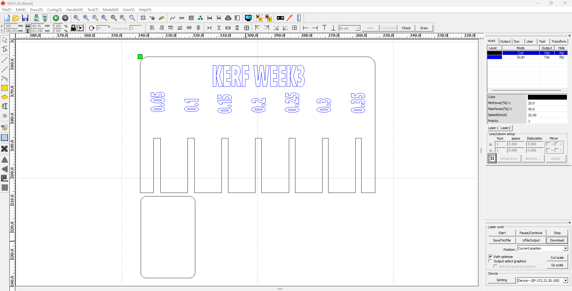
The laser parameters used for this kerf test on 2.5 mm MDF were the following:
| Material | Thickness | Operation | Speed | Power | Purpose |
|---|---|---|---|---|---|
| MDF | 2.50 mm | Cut | 22 | 40 | Kerf and tolerance test |
Since the MDF thickness was measured as 2.50 mm and the kerf test produced the best fit at 0.2 mm, this kerf value was used later in the Inventor parameter table. The editable DXF file of the kerf test is also included so the test can be reviewed and reproduced.
6. Concept Sketch
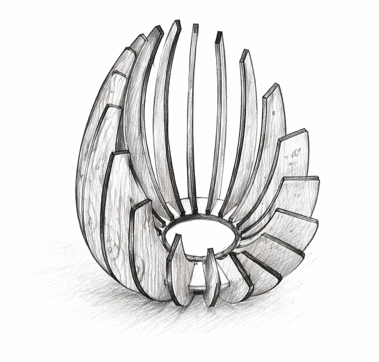
Before modeling the final digital geometry, I defined a visual approximation of the intended object. This sketch helped me decide the overall shape, the central opening, and the organic distribution of the ribs around the base.
7. Parametric Design in Autodesk Inventor
To build the construction kit, I used Autodesk Inventor. Instead of drawing the model with fixed dimensions, I created a user parameter table in Manage → Parameters. This makes the design adaptable, because if the material thickness or kerf changes, the slot dimensions and other related features can be updated consistently without redrawing the model from zero.
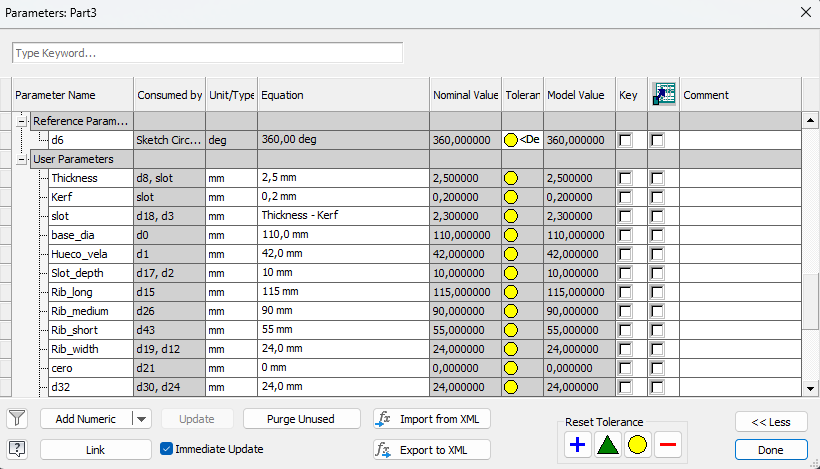
| Variable | Value | Description |
|---|---|---|
| thickness | 2.50 mm | Real MDF thickness measured with the caliper. |
| kerf | 0.20 mm | Kerf value obtained from the laser cutting test. |
| slot | thickness - kerf | Final slot width used for the press-fit joints. |
| base_diameter | Variable | Controls the outer size of the circular base. |
| candle_hole | Variable | Controls the central opening of the base. |
| slot_depth | Variable | Defines the insertion depth between ribs and base. |
| rib_height_long | Variable | Height of the longest rib. |
| rib_height_medium | Variable | Height of the medium rib. |
| rib_height_short | Variable | Height of the short rib. |
| rib_width | Variable | Controls the rib width and overall proportion. |
The most important part of the parametric strategy is that the geometry is controlled by relations, not only by absolute dimensions. In this model, the design intent is preserved through parameters that control the rib heights, the center circle, and key distances between elements so that the visual language of the object remains consistent even when the dimensions change.
The critical fabrication parameters are thickness, kerf, and slot. Thickness defines the real material value; kerf compensates for the material removed by the laser; and slot is calculated with the formula thickness - kerf. This equation is what allows the joints to adapt automatically when the material or machine behavior changes.
I also used dimensional parameters for the heights of the ribs, the center circle, and the distances that maintain the proportions of the design. In practical terms, this means I can increase or decrease the rib height without losing the overall style of the object, because the rest of the sketch remains constrained by the same parametric logic.
This became especially useful when considering different materials. If the material thickness changes, I only need to update the thickness parameter and review the kerf value. Then the slot dimension updates automatically. This is why the design is not only editable, but also adaptable to fabrication conditions.
In summary, the parametric approach in this assignment is demonstrated through: a parameter table, a dependency equation for the slots, geometric dimensions driven by variables, and the ability to modify the structure while preserving both fit and design intention.
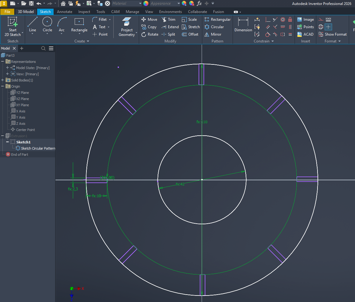
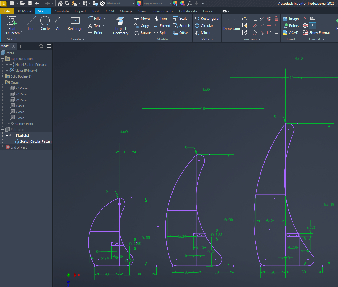
8. Sketch Development
After defining the user parameters, I created the base and the three rib types directly in sketch mode. The design includes a circular base and three different rib geometries that fit into the base through slot-based joints. For this modeling process I used circles, lines, three-point arcs, fillets, circular pattern, and move/trim operations.
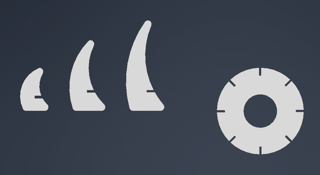
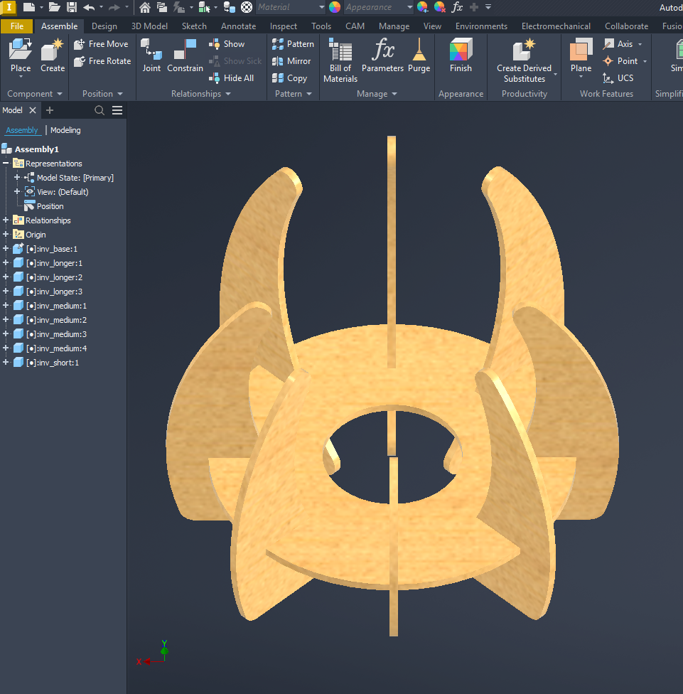
9. Digital Assembly Review
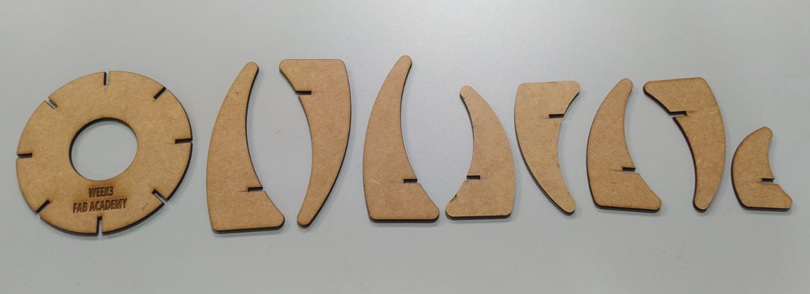
Before fabrication, I reviewed the structure digitally to verify how the pieces would behave when assembled. The final composition includes one base, three equal large ribs, four medium ribs, and one short rib. This helped me confirm the proportion, repetition, and final composition of the object before cutting.
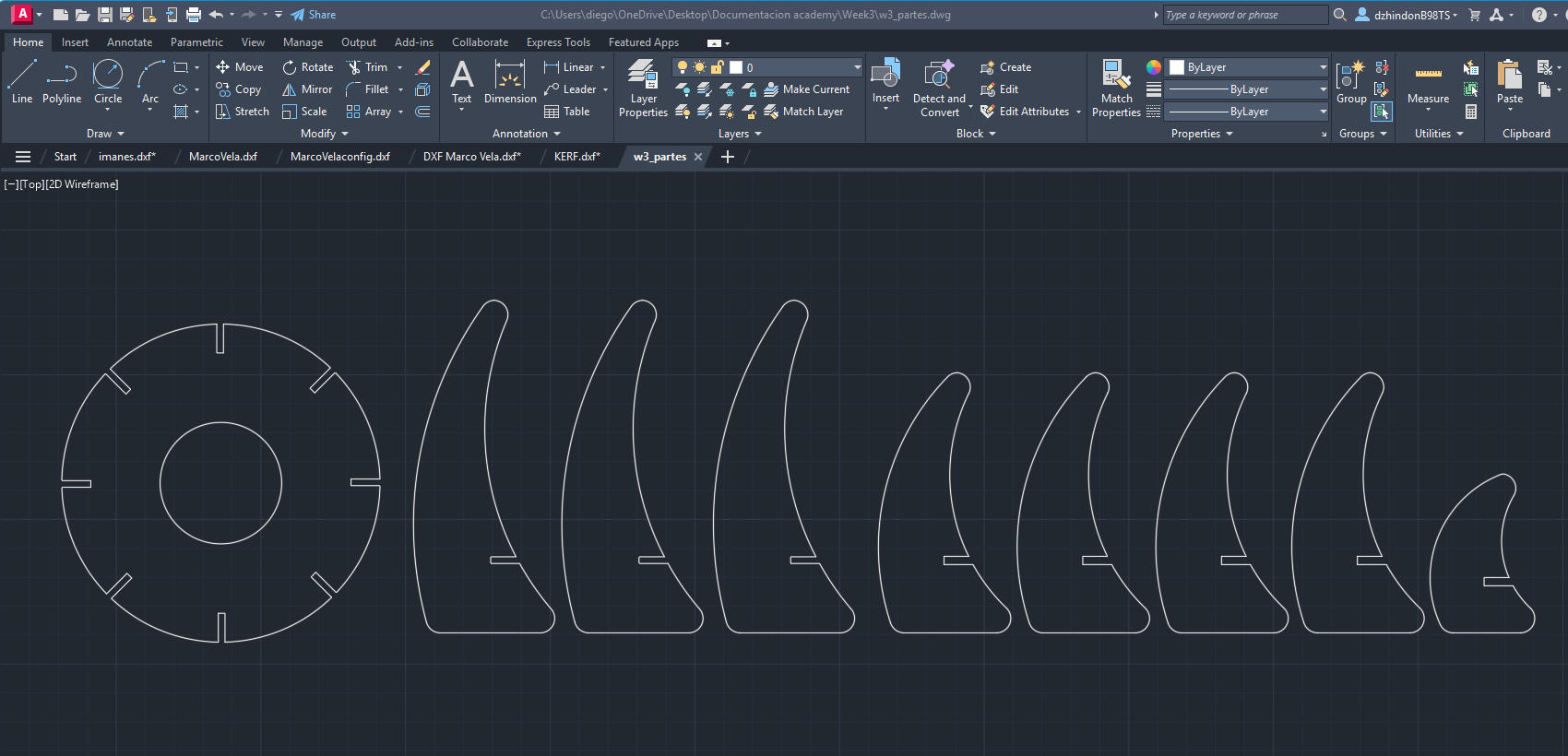
10. Exporting the Parts for Cutting
Once the solids were finished, I exported the faces of each part from Inventor into DXF format. These flat files are the final cutting profiles used in the laser workflow.
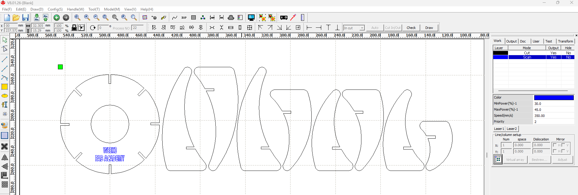
11. Cutting Preparation in RDWorks
The DXF files were imported into RDWorks to define the cutting arrangement and the machine parameters. I used two layers with different colors: blue for scan/engraving and black for cut.
| Operation | Layer Color | Speed | Power | Use |
|---|---|---|---|---|
| Scan / Engraving | Blue | 350 | 45 | Visual marking and engraved information |
| Cut | Black | 22 | 45 | Final contour cut of the pieces |
The first RDWorks setup was used to review the test arrangement, and later the final layout was organized more efficiently according to the machine work area. Since the laser cutter is connected through the lab network, the file can be sent directly from the main computer to the machine.
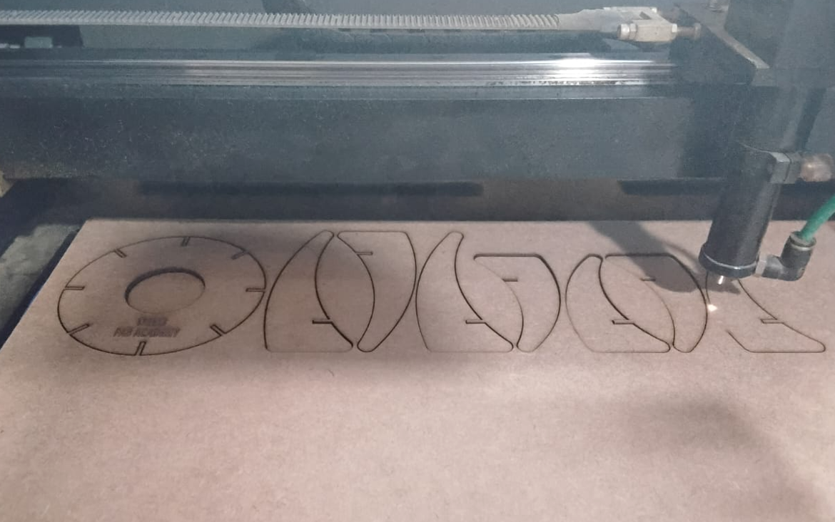
12. Final Cutting Process
After checking the fit and adjusting the kerf value, I sent the final file to the laser cutter and produced the complete set of parts in MDF.
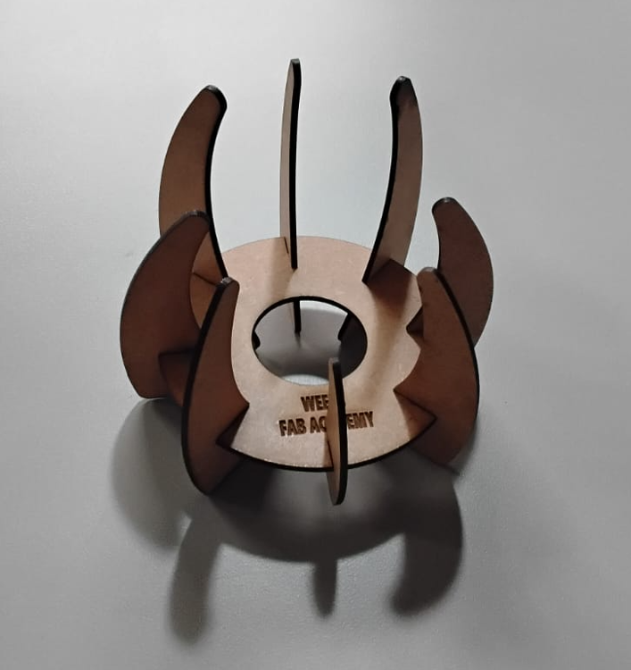
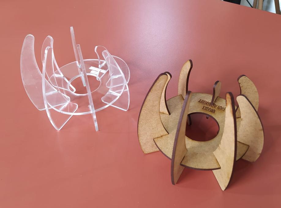
13. Final Assembly
The pieces were assembled manually using the press-fit slots. Because the model was adjusted using the measured kerf value, the structure held together correctly without glue. This confirms that the parametric strategy and the kerf compensation were effective.
14. Downloadable Files
15. Vinyl Cutting
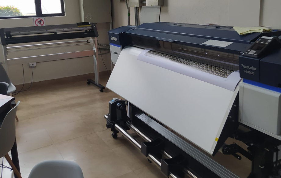
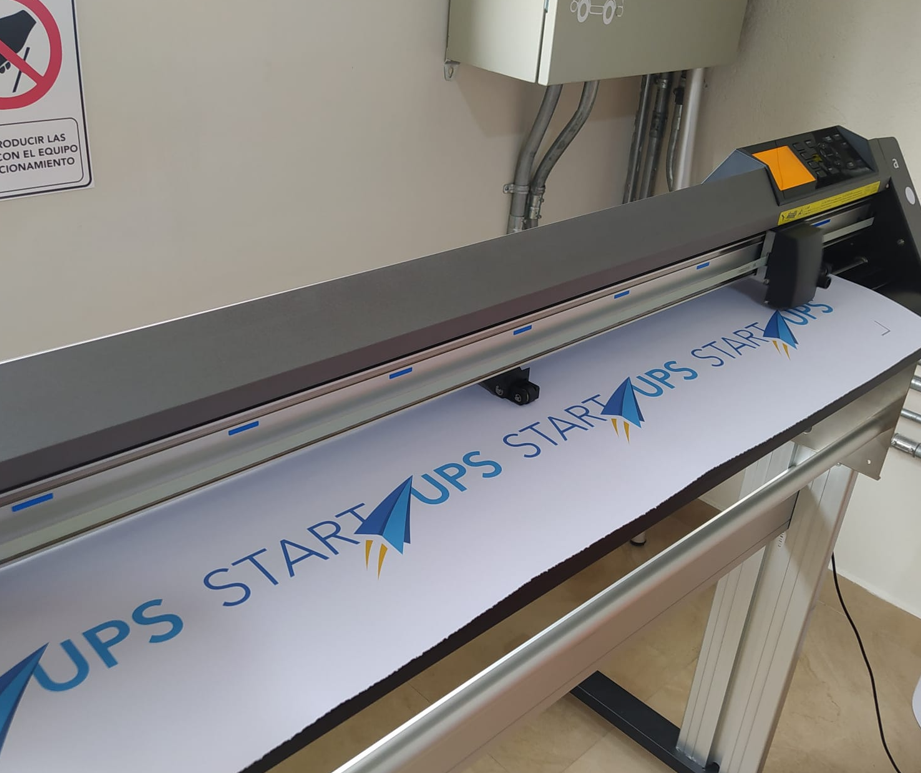
For the vinyl cutting part of the assignment, I worked with two machines: an Epson SureColor 40600 used to print the adhesive vinyl, and a Graphtec CE6000-120 Plus plotter used to cut the final label shape.
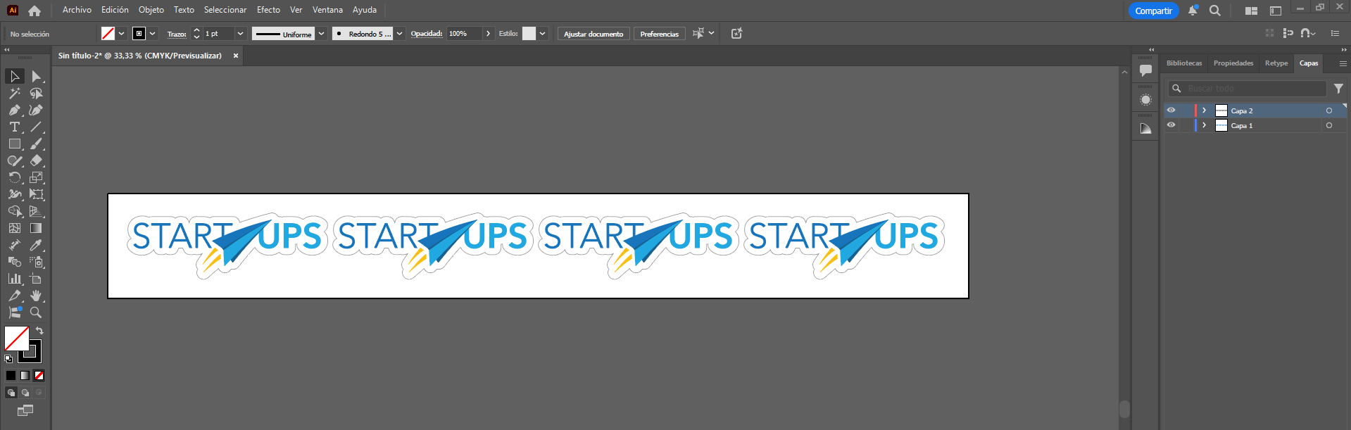
15.1 Design Preparation in Illustrator
The design was prepared in Adobe Illustrator using a workflow that separates the printable artwork from the cutting trajectory. I created two layers: the first layer contains the visible design that will be printed, and the second layer contains only the contour path used for cutting.
This separation is important because it allows the contour line to be hidden at the moment of printing, so the final graphic does not show an unwanted black outline. At the same time, the cut path remains available for the plotter in the later stage of the workflow.
For the contour generation, I used Illustrator tools to define the profile and organize the layout. This layer-based structure made the workflow cleaner and reduced the risk of sending the wrong geometry either to print or to cut.
15.2 Registration Marks and Print Preparation
To connect the printing stage with the contour cutting stage, I used the Illustrator plugin Cutting Master 4. In this plugin, the first important function was the generation of registration marks. These marks are placed in the four corners of the design area and work as reference points so the plotter can later identify the exact position of the printed job.
In my case, the registration marks were placed with a distance of 15 cm from the outer edges of the total design area. This created a safe and readable margin for the optical detection process. The marks act like positional references in quadrants or L-shaped corners, allowing the cutting system to reconstruct the print location and align the cutting trajectory correctly.
Once the marks were generated, I exported the file as PDF with the cut contour layer hidden. This way, only the visible artwork and the registration references were included in the print file.
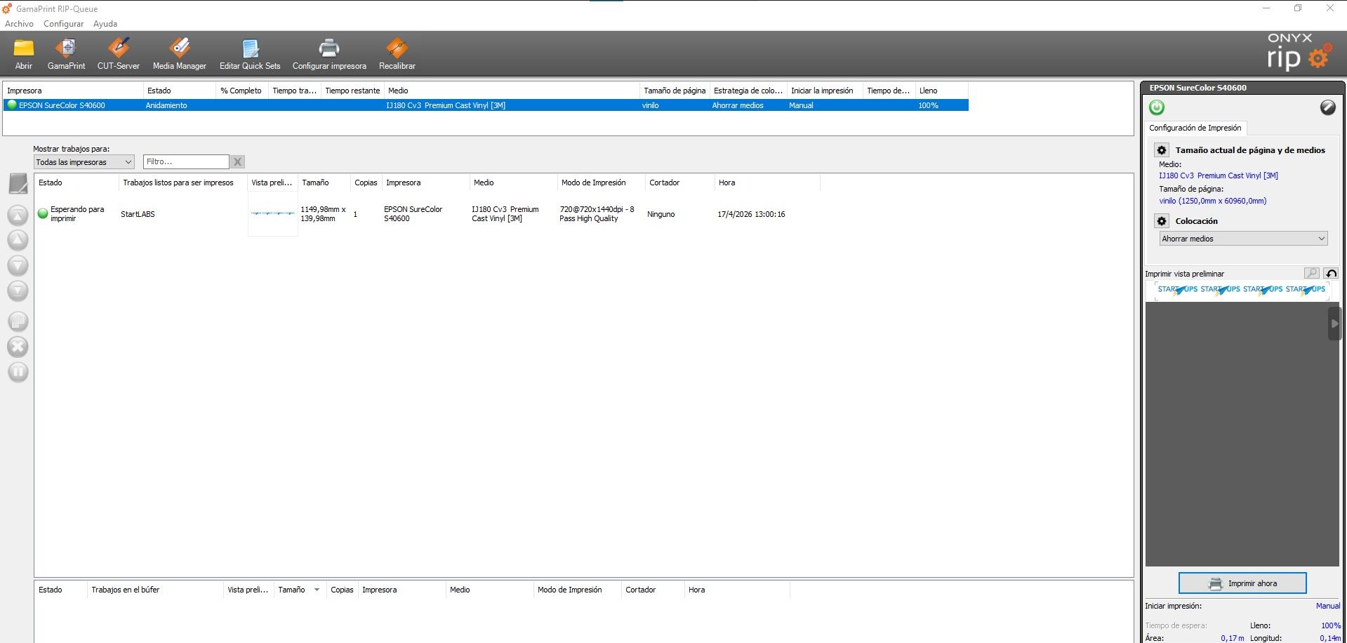
15.3 Printing with RIP Queue
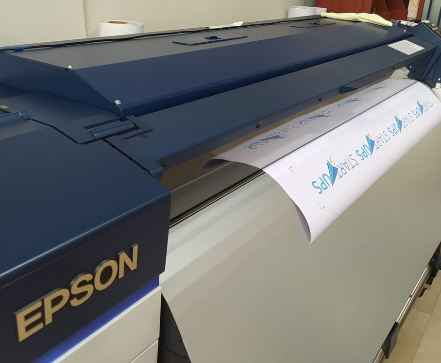
After preparing the PDF, I sent the job to print using RIP Queue. In this step, I selected the correct printer and defined the material configuration for the adhesive vinyl. This stage is important because the printing profile directly affects color output, scaling, and media handling before cutting.
Once the print was completed, the vinyl sheet already contained both the visible design and the registration marks needed for the next contour-cutting stage.
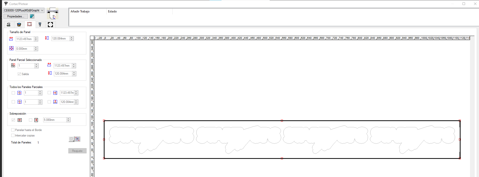
15.4 Contour Cutting on the Graphtec Plotter
After printing, I moved the vinyl to the Graphtec CE6000-120 Plus plotter. The first task in the machine was to define the effective work area. For this, the Graphtec uses sensors that detect the loaded material dimensions in both width and length.
Then, from Illustrator, I used the second key option in Cutting Master 4: cut / plot. Before sending the job, I manually positioned the plotter head over the lower-right registration mark, which serves as the starting reference for the optical reading sequence.
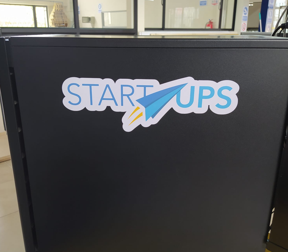
Once the job was sent, the system used its camera and sensor workflow to detect the four printed registration marks. After identifying those references, the machine automatically corrected the cutting position and executed the contour cut following the path stored in the hidden cut layer.
This process is important because it compensates for small positional deviations between printing and loading, ensuring that the final cut matches the printed design accurately. The result is a better alignment between graphics and contour.
16. Conclusions
- Using parametric design in Inventor made the model much more flexible, because the slot dimensions could be updated by changing only a few variables.
- Measuring the real MDF thickness was essential, since the sheet thickness was 2.50 mm and not just a nominal value.
- The kerf test was one of the most important stages, because it allowed me to compare tolerances systematically and determine that 0.2 mm produced the best press-fit result.
- What worked best was linking the slot equation to the parameters thickness and kerf, because this made the joints adaptable without redrawing the model.
- The tolerance test also showed clearly what did not work: values below 0.2 mm produced joints that were too tight, while larger values progressively made the fit too loose.
- Working with a parameter table helped keep the relation between the base and the ribs consistent throughout the design process, especially when modifying rib heights and internal distances.
- The final MDF assembly confirmed that the press-fit strategy worked correctly and that the structure could be assembled without glue.
- In the vinyl workflow, using separate layers for artwork and cut contour was essential, because it kept the print clean while preserving the correct cut path.
- I also learned that registration marks and plotter alignment are critical in print-and-cut workflows, since the quality of the final result depends on accurate mark detection and contour tracking.
- Overall, this assignment helped me understand that computer-controlled cutting is not only about drawing geometry, but about relating design, tolerances, machine parameters, and fabrication behavior in a controlled way.