NODO

Ultrasonic Sensor Distance Measurement System
Probe an input device's analog levels and digital signals and understand how data is transmitted to a microcontroller.
Measure a physical variable using a sensor connected to a microcontroller and read its data.
The sensor was analyzed by observing its digital signals. The TRIG pin sends a pulse, and the ECHO pin returns a signal whose duration represents distance.
The system behaves as a digital signal carrying analog information through time. Noise and fluctuations were observed and reduced using averaging.
A functional system was developed to measure distance using an ultrasonic sensor connected to a microcontroller. The system successfully reads, processes, and responds to real-world data.
This project focuses on the integration of an ultrasonic distance sensor with a microcontroller in order to measure physical distance and generate a visual response using LEDs. The system captures real-time distance data from the environment and translates it into a simple but effective output logic, allowing the user to understand proximity conditions through visual indicators.
The system reads the distance between the sensor and an object and activates different LEDs depending on proximity. This behavior replicates a basic sensing logic commonly used in industrial automation systems, such as object detection in conveyor belts, safety distance monitoring, and proximity alerts in manufacturing environments.
The main objective of this development is to serve as a foundational prototype for a conveyor belt system controlled by proximity sensors. In this context, the sensor would detect the presence or position of objects along the line, enabling or disabling movement depending on specific conditions. This type of logic is widely applied in assembly cells, where precise detection is required to ensure proper workflow, avoid collisions, and maintain production efficiency.
Through this implementation, the project demonstrates how a simple input device can be used to create intelligent behavior in a system, forming the basis for more advanced automation processes such as object counting, flow control, and synchronized operations within a modular assembly station.
During the development of this project, two microcontroller platforms were evaluated for integrating the ultrasonic sensor: the XIAO ESP32C3 and the Arduino Uno/Nano. The comparison focused on compatibility, ease of implementation, and stability during testing.
| Feature | XIAO ESP32C3 | Arduino Uno / Nano |
|---|---|---|
| Operating Voltage | 3.3V | 5V |
| Sensor Compatibility | Requires voltage divider | Direct connection |
| Circuit Complexity | Higher | Lower |
| Stability | Moderate | High |
| Ease of Debugging | More complex | Simpler |
Based on this comparison, the Arduino Uno/Nano was selected as the most viable solution. Its 5V logic allows direct connection with the ultrasonic sensor without requiring additional components such as voltage dividers. This simplifies the circuit, reduces potential errors, and improves system reliability during prototyping.
This decision was key to achieving stable measurements and a functional system, especially in the context of developing a proximity-based control mechanism for a conveyor belt within an assembly cell.
This sensor measures distance using ultrasonic waves. It emits a pulse and measures the return time to calculate distance.
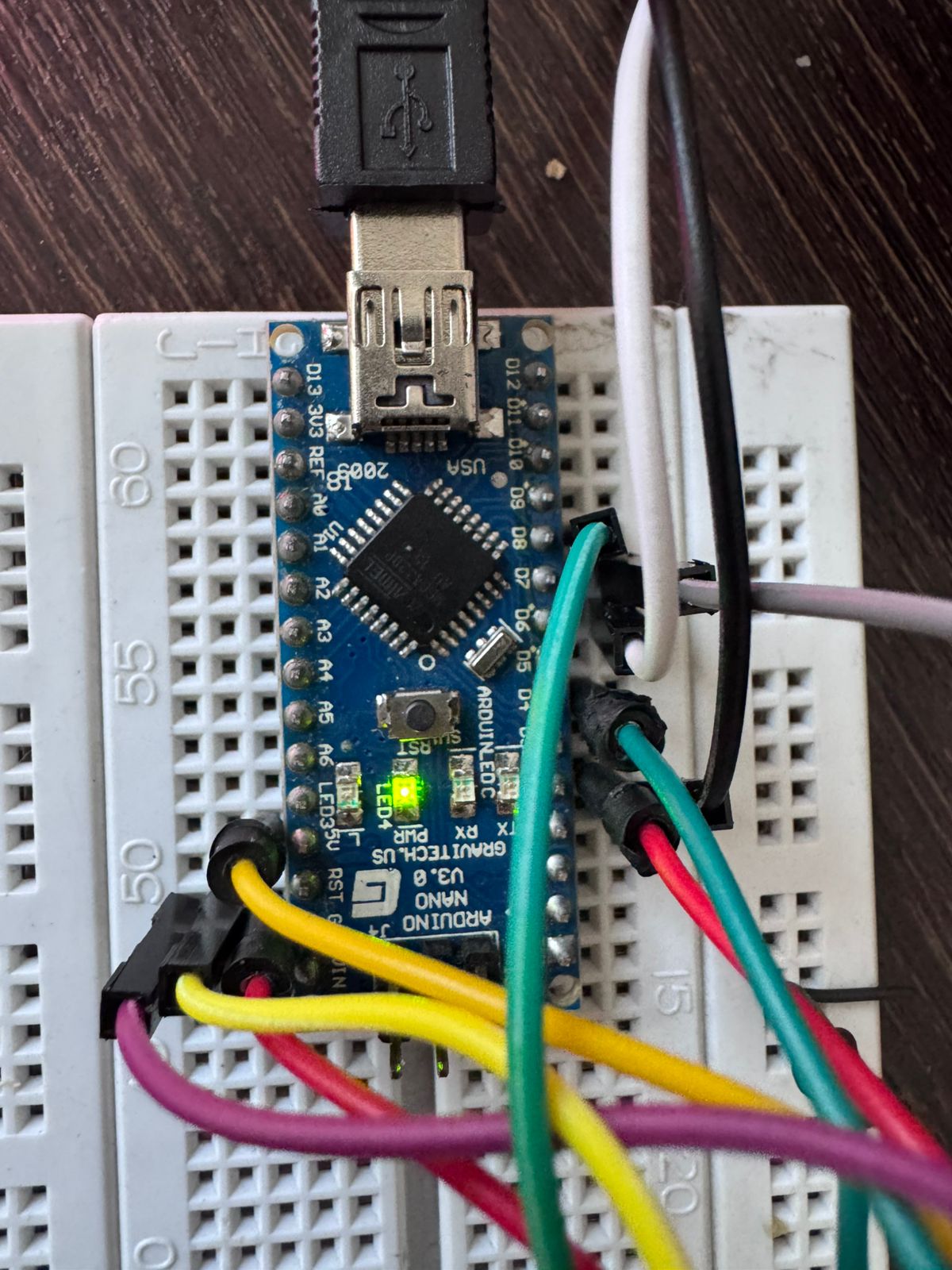
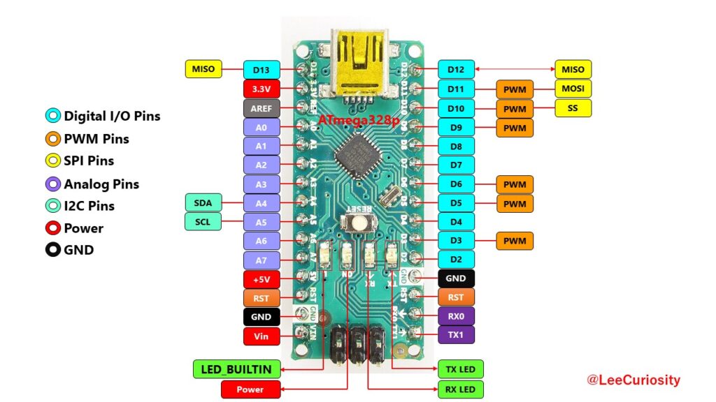
A compact microcontroller based on ATmega328P, operating at 5V and widely used for prototyping embedded systems.
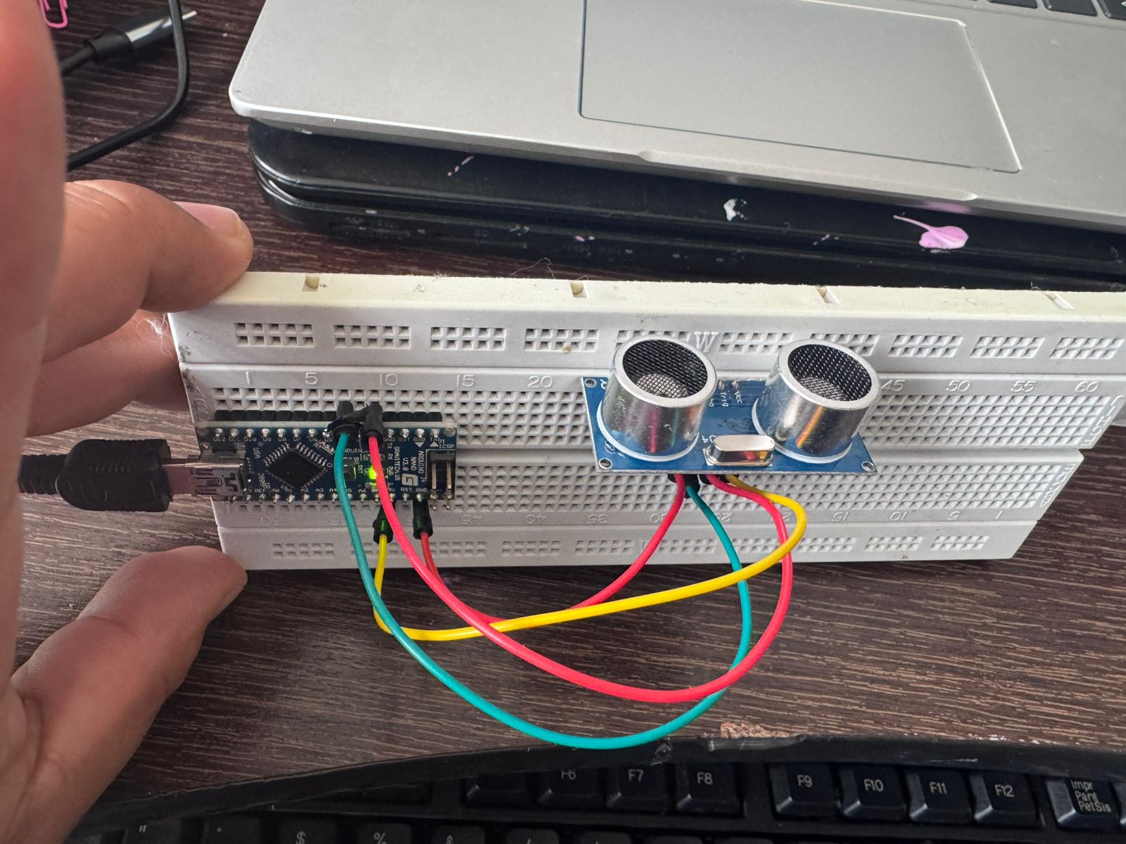
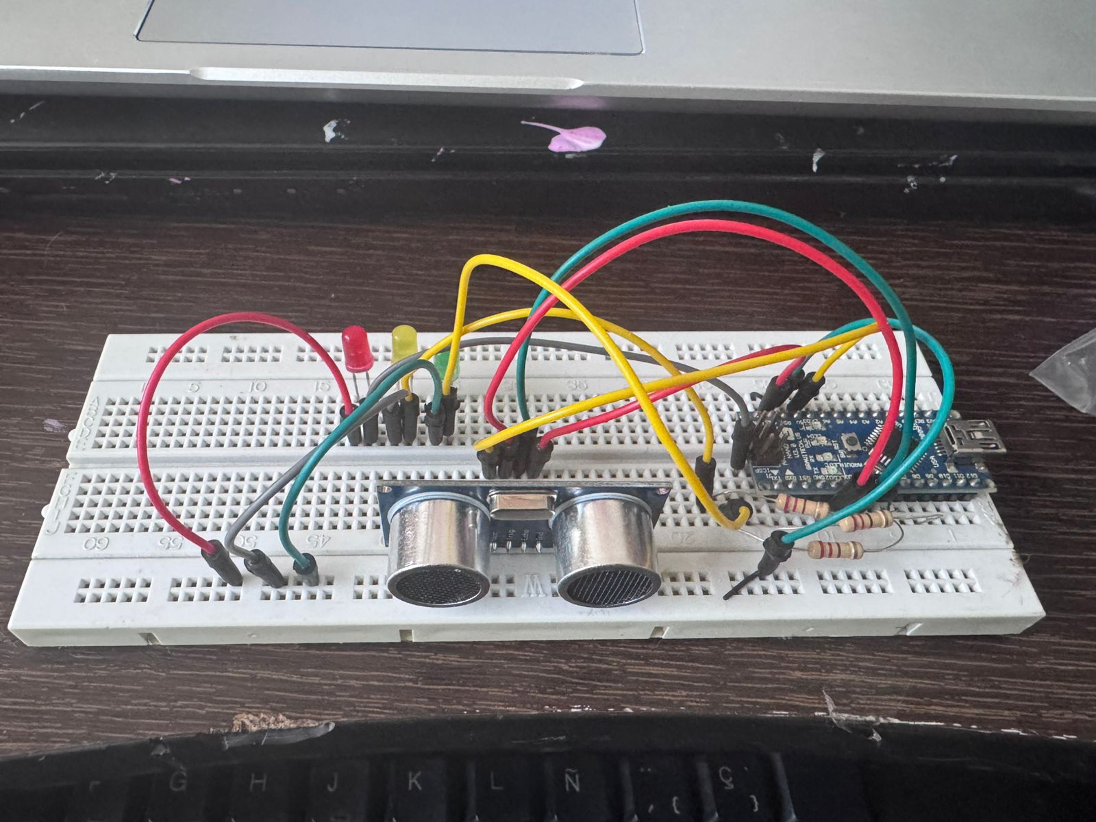
The ultrasonic sensor HC-SR04 is connected to the microcontroller using four main pins that enable power supply and signal communication. Proper configuration of these connections is essential to ensure accurate distance measurement and stable system performance.
HC-SR04        Arduino Nano
---------      --------------
VCC   -------- 5V
GND   -------- GND
TRIG  -------- D2
ECHO  -------- D4
The main objective of this configuration is to create a proximity indicator system similar to a traffic light. The system evaluates the distance measured by the sensor and activates different LEDs according to predefined ranges.
This behavior allows the system to visually represent proximity levels, making it easy to interpret distance conditions in real time. Such logic is commonly used in industrial environments to monitor object positioning, detect presence, and ensure safe operation in automated processes.
This traffic light-style indicator serves as a foundational model for more complex systems, such as conveyor belt control in assembly cells, where proximity detection can be used to trigger actions like starting, stopping, or regulating movement.
D6 → Green LED → Resistor → GND
D7 → Yellow LED → Resistor → GND
D8 → Red LED → Resistor → GND
D6 → Green LED → Resistor → GND
D7 → Red LED → Resistor → GND
This code implements a distance measurement system using an ultrasonic sensor and controls two LEDs based on proximity. The program is structured into three main parts: pin definition, distance measurement function, and control logic.
#define TRIG 2
#define ECHO 4

#define LED_VERDE 6
#define LED_ROJO 7
The TRIG and ECHO pins are used to communicate with the ultrasonic sensor. TRIG sends the signal, and ECHO receives it. The LEDs are connected to digital pins 6 and 7, acting as visual indicators of distance.
long readDistance() {
  long total = 0;

  for (int i = 0; i < 5; i++) {
    digitalWrite(TRIG, LOW);
    delayMicroseconds(2);
    digitalWrite(TRIG, HIGH);
    delayMicroseconds(10);
    digitalWrite(TRIG, LOW);

    long duration = pulseIn(ECHO, HIGH);
    long distance = duration * 0.034 / 2;

    total += distance;
    delay(50);
  }

  return total / 5;
}
This function calculates the distance by sending an ultrasonic pulse and measuring the time it takes to return. The key steps are:
Averaging reduces noise and provides more reliable measurements, which is important in real-world environments.
void setup() {
  pinMode(TRIG, OUTPUT);
  pinMode(ECHO, INPUT);
  pinMode(LED_VERDE, OUTPUT);
  pinMode(LED_ROJO, OUTPUT);
  Serial.begin(9600);
}
The setup function initializes the pin modes and starts serial communication. TRIG is configured as output, ECHO as input, and both LEDs as outputs. The serial monitor is used to display distance values.
void loop() {
  long distance = readDistance();

  if (distance <= 0 || distance > 400) return;

  Serial.print("Distance: ");
  Serial.println(distance);

  digitalWrite(LED_VERDE, LOW);
  digitalWrite(LED_ROJO, LOW);

  if (distance > 20) {
    digitalWrite(LED_VERDE, HIGH);
  } else {
    digitalWrite(LED_ROJO, HIGH);
  }

  delay(200);
}
The loop continuously reads the distance and applies decision logic:
The code creates a simple proximity detection system. It translates sensor input into a binary output:
This logic is the foundation for more complex automation systems such as conveyor belt control, where object detection can trigger actions like starting or stopping movement.
#define TRIG 2
#define ECHO 4

#define LED_VERDE 6
#define LED_ROJO 7

long readDistance() {
  long total = 0;

  for (int i = 0; i < 5; i++) {
    digitalWrite(TRIG, LOW);
    delayMicroseconds(2);
    digitalWrite(TRIG, HIGH);
    delayMicroseconds(10);
    digitalWrite(TRIG, LOW);

    long duration = pulseIn(ECHO, HIGH);
    long distance = duration * 0.034 / 2;

    total += distance;
    delay(50);
  }

  return total / 5;
}

void setup() {
  pinMode(TRIG, OUTPUT);
  pinMode(ECHO, INPUT);
  pinMode(LED_VERDE, OUTPUT);
  pinMode(LED_ROJO, OUTPUT);
  Serial.begin(9600);
}

void loop() {
  long distance = readDistance();

  if (distance <= 0 || distance > 400) return;

  Serial.print("Distance: ");
  Serial.println(distance);

  digitalWrite(LED_VERDE, LOW);
  digitalWrite(LED_ROJO, LOW);

  if (distance > 20) {
    digitalWrite(LED_VERDE, HIGH);
  } else {
    digitalWrite(LED_ROJO, HIGH);
  }

  delay(200);
}
The primary variable measured in this project is distance. The system uses an ultrasonic sensor to detect how far an object is from the sensor in real time. This is essential for implementing proximity-based logic in automation systems.
The sensor operates by emitting an ultrasonic pulse and measuring the time it takes for the signal to return after bouncing off an object. This time is then converted into distance using the speed of sound. The microcontroller processes this signal and determines which output should be activated.
This sensing mechanism allows the system to detect object presence and position, forming the basis for proximity control in applications such as conveyor belts and assembly stations.
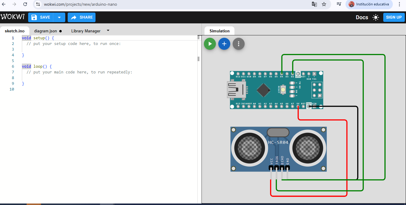
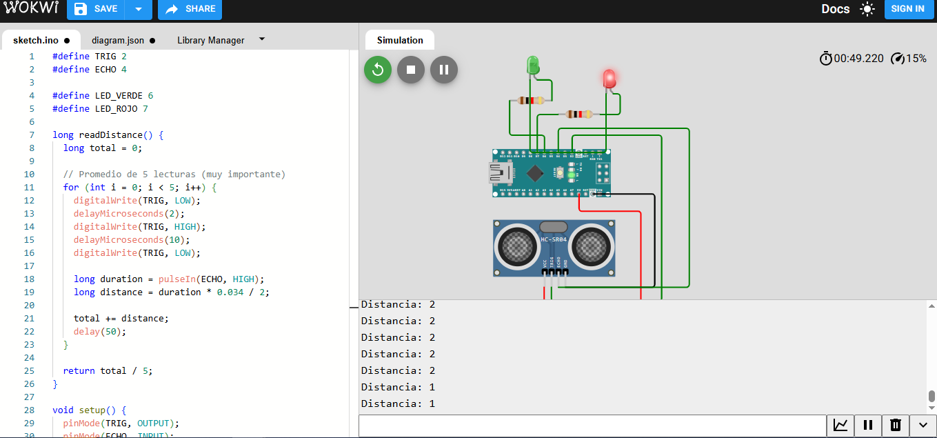
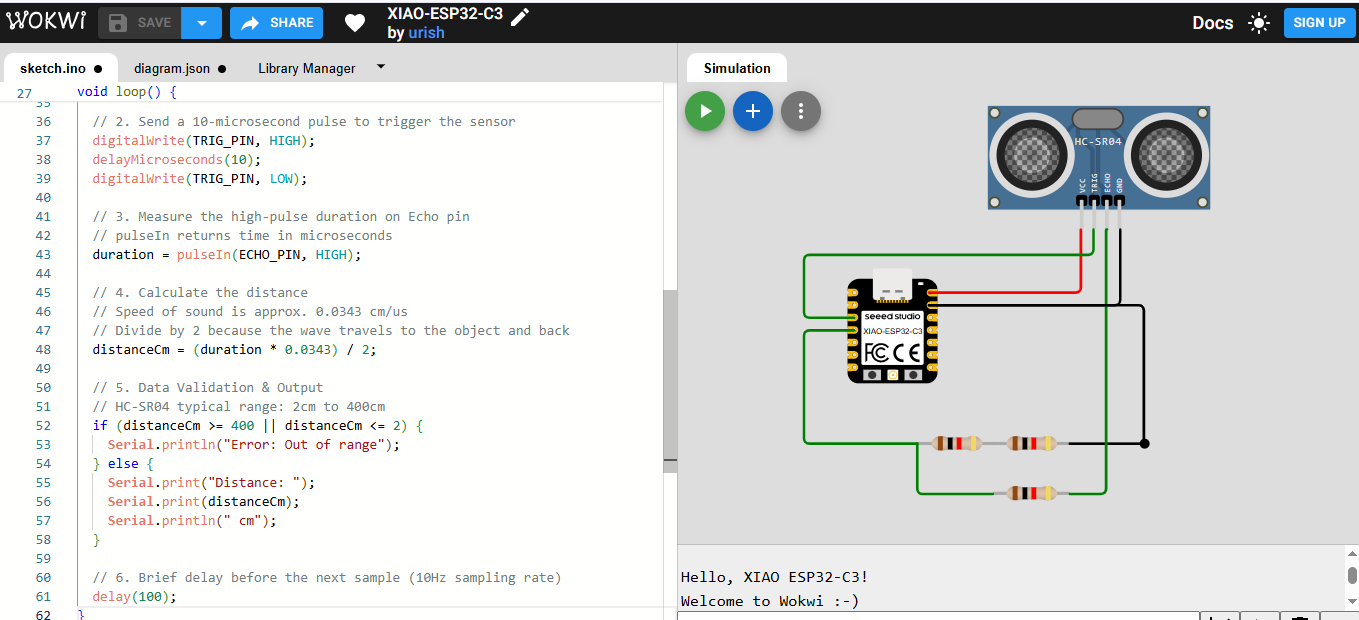
Before implementing the system physically, a simulation was developed using Wokwi. This allowed testing the behavior of the ultrasonic sensor and validating the logic without the need for hardware.
The simulation reproduces the interaction between the sensor and the microcontroller, generating virtual distance values and observing how the outputs respond. This step is essential to verify that the logic is correct and that the system behaves as expected.
The code used in the simulation includes the generation of the trigger pulse, the reading of the echo signal using the pulseIn() function, and the calculation of distance. Based on this value, conditional statements activate the corresponding outputs.
Additionally, averaging techniques were introduced to reduce noise and improve measurement stability, which is critical for real-world applications.
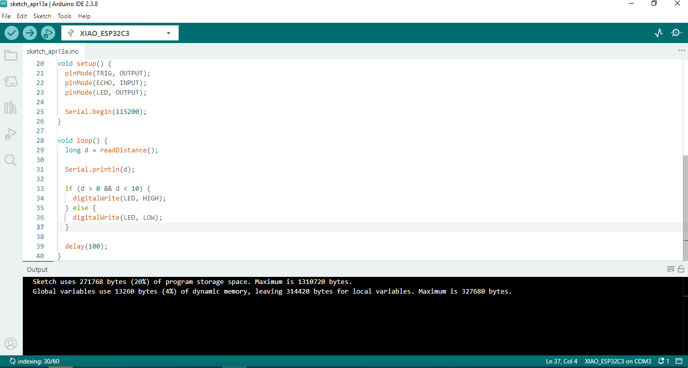
After validating the system through simulation, the next step was transferring the code to the physical microcontroller using the Arduino IDE. This process involves compiling the code and uploading it to the board through a USB connection.
First, the correct board and processor configuration must be selected in the Arduino IDE. Then, the appropriate communication port is chosen to establish a connection between the computer and the microcontroller.
Once the configuration is complete, the code is compiled to check for errors. If the compilation is successful, the program is uploaded to the board. During this process, the IDE communicates with the microcontroller’s bootloader to transfer the instructions.
After uploading, the system begins executing the program immediately. The sensor starts measuring distance, and the outputs respond according to the defined logic. The Serial Monitor can be used to visualize real-time data and verify system performance.
This step completes the transition from simulation to real-world implementation, ensuring that the designed system operates correctly under physical conditions.
 Download Arduino Code
| Component | Description | Quantity |
|---|---|---|
| Arduino Nano / Uno | Microcontroller for processing signals | 1 |
| HC-SR04 Sensor | Ultrasonic distance sensor | 1 |
| LEDs (Green, Yellow, Red) | Visual indicators | 3 |
| Resistors (220Ω) | Current limiting resistors | 3 |
| Breadboard | Prototyping platform | 1 |
| Jumper Wires | Connections between components | Several |
HC-SR04        Arduino
VCC   -------- 5V
GND   -------- GND
TRIG  -------- D2
ECHO  -------- D4

LED VERDE   → D6 → Resistor → GND
LED AMARILLO→ D7 → Resistor → GND
LED ROJO    → D8 → Resistor → GND
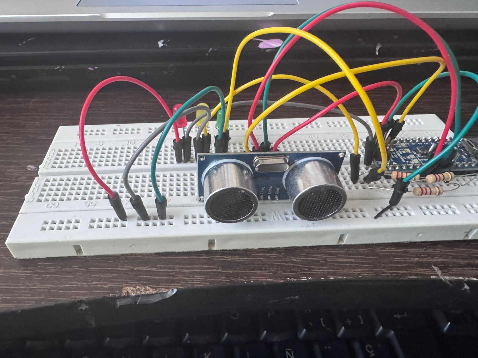
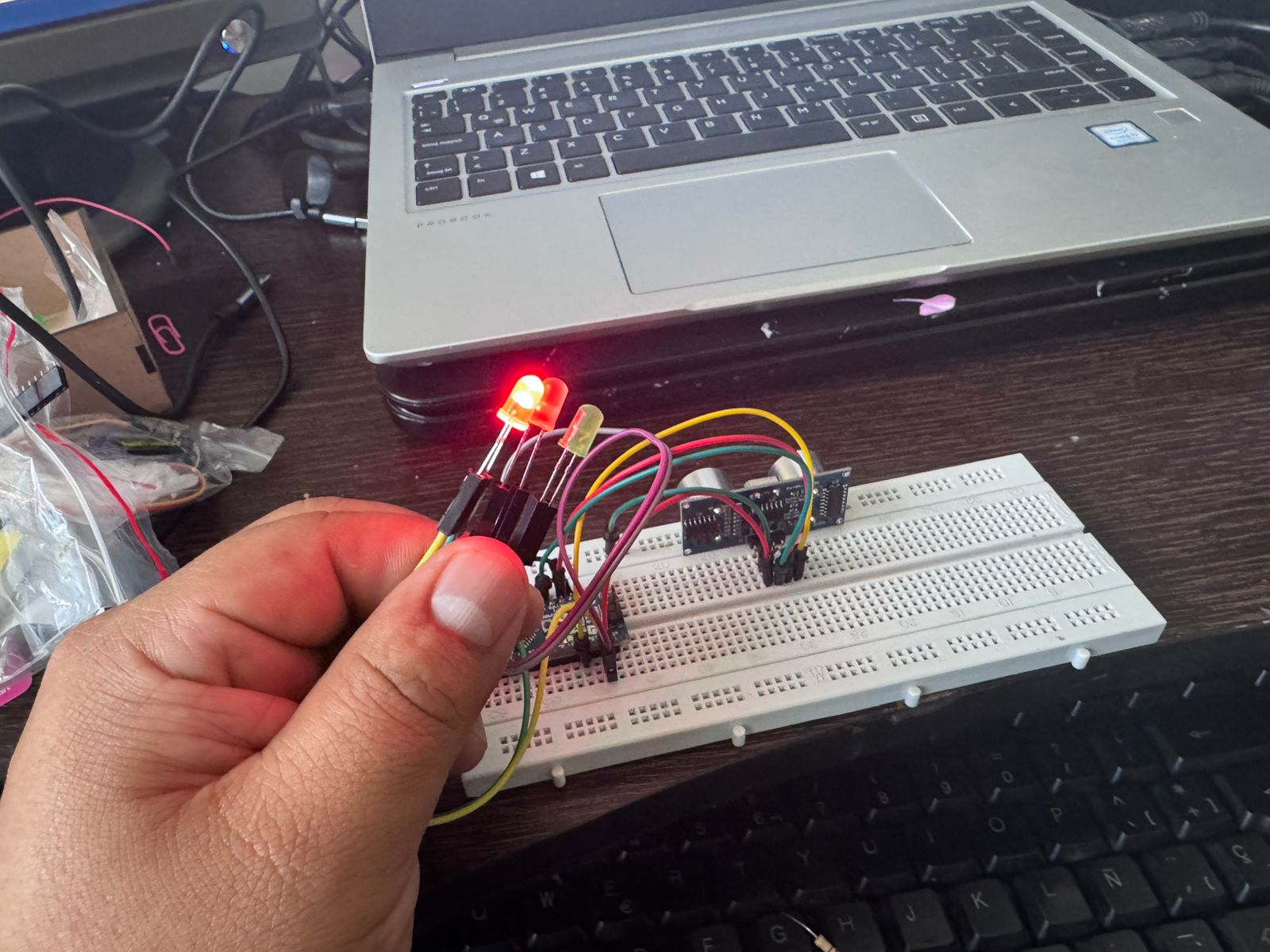
The final prototype demonstrates a proximity-based indicator system using three LEDs. As an object approaches the ultrasonic sensor, the system changes its visual output following a traffic light logic.
When the object is far from the sensor, the green LED turns on, indicating a safe distance. As the object gets closer, the yellow LED activates, representing an intermediate state. When the object is very close, the red LED turns on, signaling a proximity alert.
This behavior simulates a proximity control system intended for a conveyor belt in an assembly cell, where object detection is used to regulate movement, ensure safety, and maintain process flow.
During the development of this assignment, several technical challenges were encountered, particularly during the initial implementation using the XIAO ESP32C3. These issues were critical in understanding the importance of hardware compatibility and signal integrity in embedded systems.
One of the main problems identified was the difference in operating voltage between the XIAO ESP32C3 and the ultrasonic sensor. The XIAO operates at 3.3V logic, while the HC-SR04 sensor works at 5V.
This mismatch created a risk of damaging the microcontroller, particularly in the ECHO pin, which outputs a 5V signal. To mitigate this, a voltage divider was required, adding extra components and increasing circuit complexity.
When working with the XIAO, unstable and inconsistent readings were observed. The sensor occasionally returned incorrect values or no signal at all. This made debugging more difficult and reduced system reliability during early testing stages.
These issues were partly due to voltage adaptation and also to the sensitivity of the ultrasonic sensor to electrical noise and timing precision.
Additional problems were encountered when configuring the development environment. Incorrect board selection in the Arduino IDE caused compilation and upload errors, preventing the code from running properly. Serial communication setup also required verification to ensure correct data visualization.
During prototyping, some unexpected behaviors were caused by incorrect wiring in the breadboard. For example, LEDs turning on simultaneously were traced back to shared rows or incorrect grounding. These issues emphasized the importance of understanding breadboard connectivity.
The HC-SR04 sensor showed limitations at very short distances, where readings became unstable or inaccurate. This required adjusting thresholds and implementing averaging techniques to stabilize the measurements.
To overcome these challenges, the system was migrated from the XIAO ESP32C3 to the Arduino Uno/Nano. This decision simplified the circuit by eliminating the need for voltage conversion and improved signal stability.
The Arduino platform allowed direct sensor integration, easier debugging, and more reliable performance, which was essential for achieving the objectives of the assignment.
These challenges provided valuable learning outcomes, reinforcing the importance of selecting appropriate hardware, validating connections, and applying systematic debugging strategies in embedded system development.
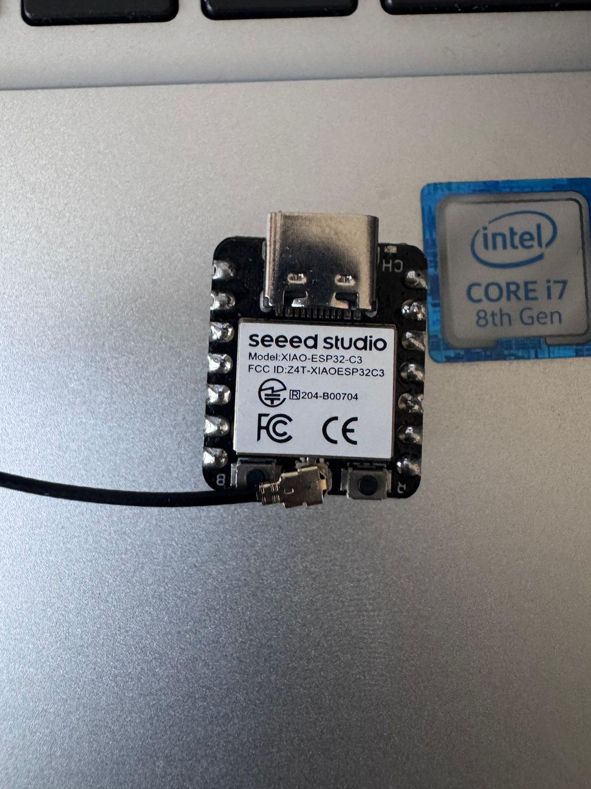
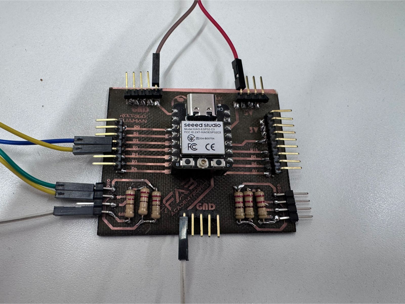
The goal of this project is to measure physical distance using an ultrasonic sensor (HC-SR04) and a XIAO ESP32-C3 microcontroller. Since the sensor operates at 5V and the MCU at 3.3V, a voltage divider was designed using resistors to ensure signal compatibility and hardware safety.
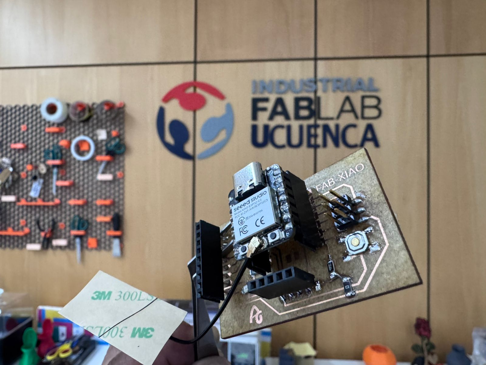
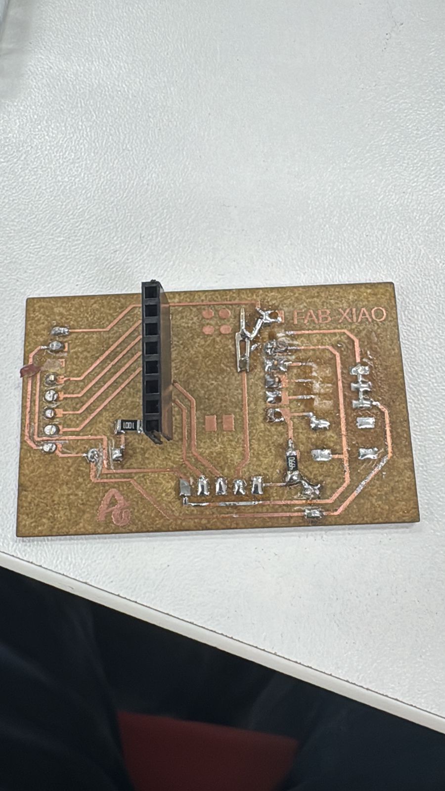
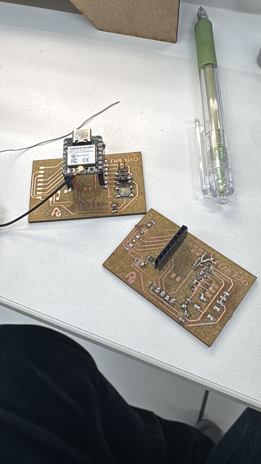
As part of the assignment, a custom PCB based on the XIAO ESP32-C3 (FabXIAO) was fabricated to integrate the input device (HC-SR04) in a compact and reliable way.
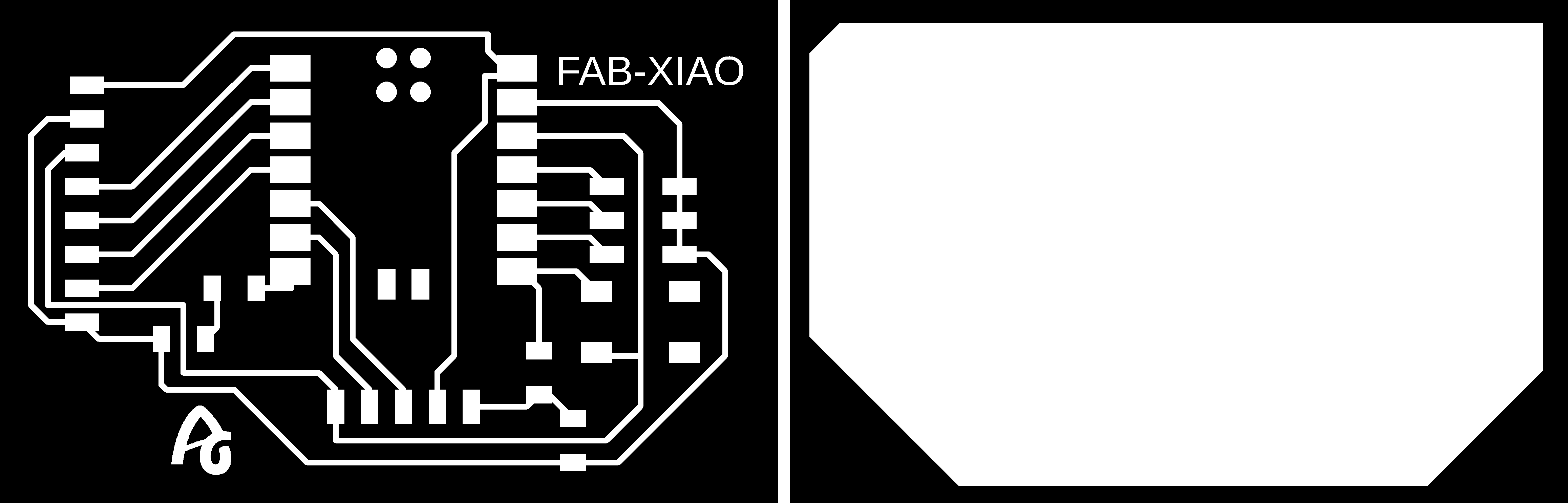
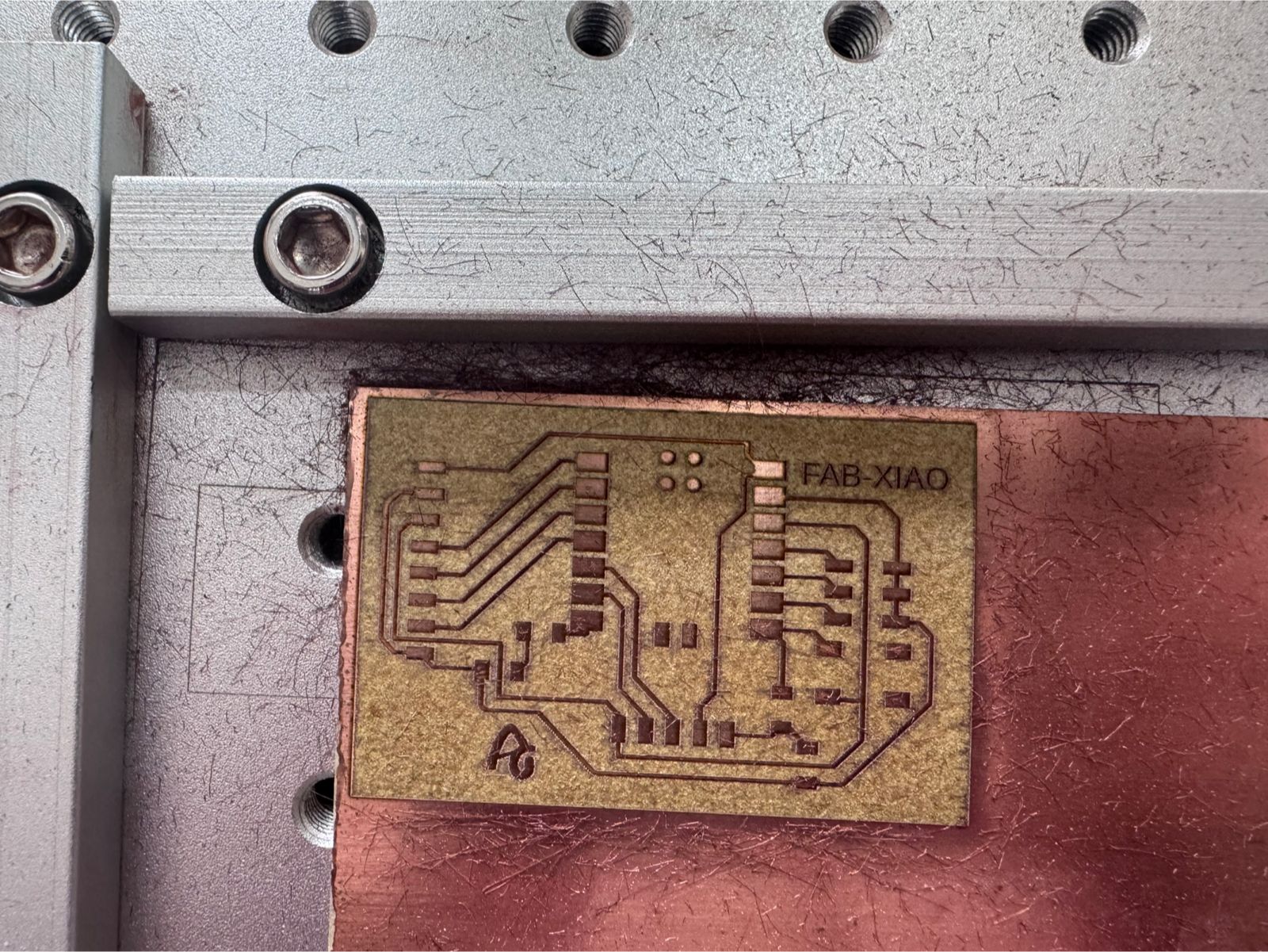
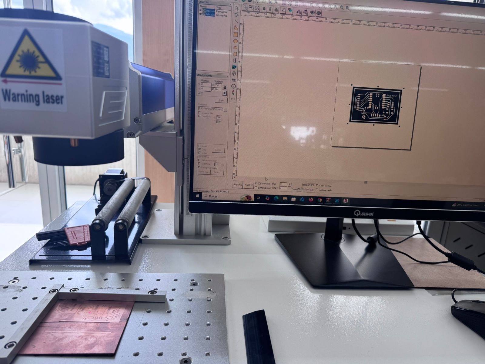
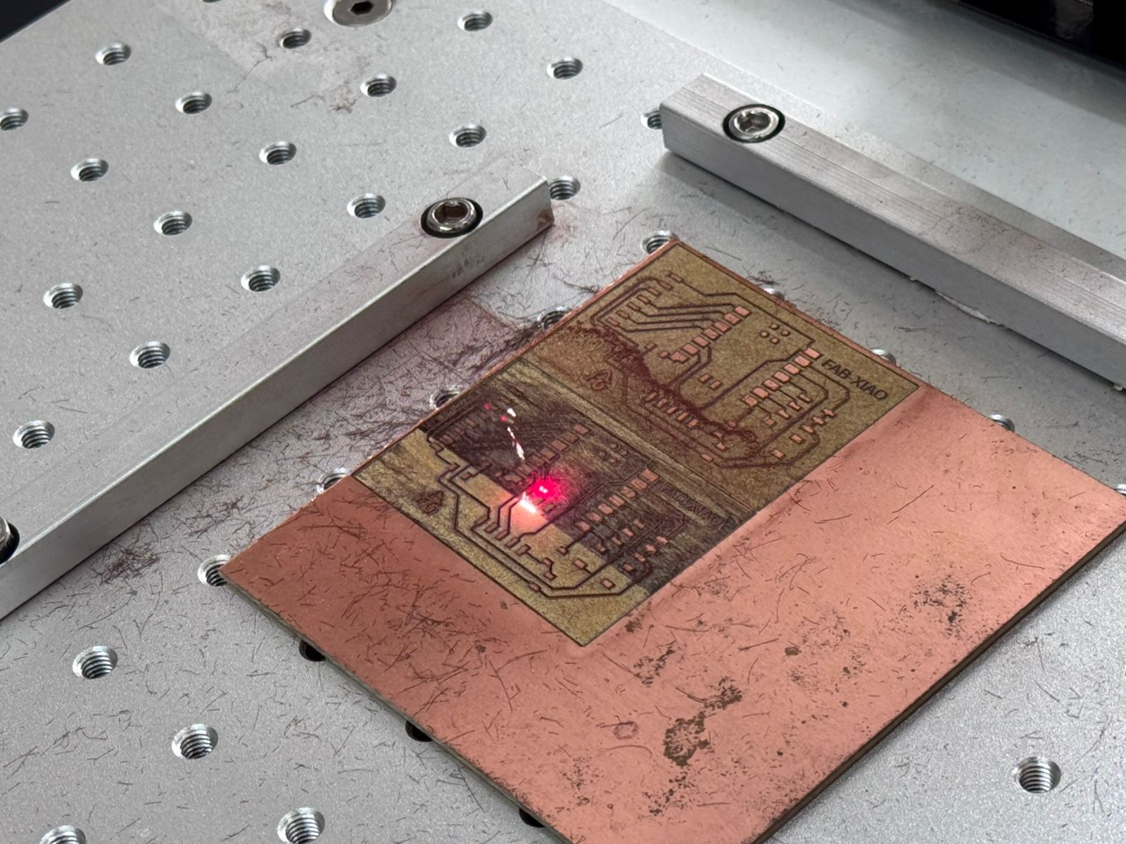
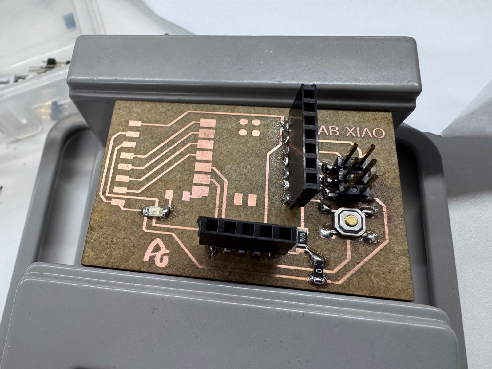
The FabXIAO board was successfully fabricated using a fiber laser process, resulting in precise traces and a clean PCB, ready to interface with the HC-SR04 sensor.
For more information about FabXIAO development, visit:
FabXIAO Documentation – Adrian Torres
| Component | Quantity | Purpose |
|---|---|---|
| XIAO ESP32-C3 | 1 | Main microcontroller (RISC-V architecture). |
| HC-SR04 Sensor | 1 | Ultrasonic transducer (Input Device). |
| 220 Ω Resistor | 3 | Used for the 5V to 3.3V voltage divider. |
| Breadboard | 1 | For prototyping the circuit. |
| Jumper Wires | 5-7 | Electrical interconnections. |
Follow these steps to ensure a safe and functional assembly of the circuit:
Place the XIAO ESP32-C3 on the breadboard. Connect the 5V pin of the XIAO to the positive rail and the GND pin to the negative rail.
Insert the HC-SR04 sensor into the breadboard. Connect its VCC to the 5V rail and GND to the ground rail.
Run a jumper wire directly from XIAO pin D2 (GPIO 4) to the Trig pin on the sensor.
Before plugging in the USB cable, double-check that the 5V output from the sensor's Echo pin passes through the resistor network and does not go directly into the XIAO.
The most critical part of the hardware is the Voltage Divider on the Echo pin.
VCC is connected to the XIAO 5V pin. Both share a common GND.D2 (GPIO 4) connects directly to the sensor's Trig pin. The sensor accepts 3.3V as a logical "High".Echo pin outputs 5V.Vout = Vin * (R2 / (R1 + R2)) ≈ 3.33V
/**
 * FabAcademy - Input Devices
 * Final Code: Ultrasonic Distance Measurement
 */

// Pin Configuration
const int TRIG_PIN = 4; // XIAO Pin D2
const int ECHO_PIN = 5; // XIAO Pin D3

void setup() {
  // Serial communication for data visualization
  Serial.begin(115200);

  // Initialize Pins
  pinMode(TRIG_PIN, OUTPUT);
  pinMode(ECHO_PIN, INPUT);

  Serial.println("System Online: HC-SR04 + ESP32-C3");
}

void loop() {
  long duration;
  float distanceCm;

  // Clear trigger to ensure a clean HIGH pulse
  digitalWrite(TRIG_PIN, LOW);
  delayMicroseconds(2);

  // Send 10 microsecond pulse
  digitalWrite(TRIG_PIN, HIGH);
  delayMicroseconds(10);
  digitalWrite(TRIG_PIN, LOW);

  // Measure the duration of the Echo pulse in microseconds
  // timeout set to 30000us (approx 5 meters)
  duration = pulseIn(ECHO_PIN, HIGH, 30000);

  // Physics: Distance = (Time * Speed of Sound) / 2
  // Speed of Sound = 0.0343 cm/us
  distanceCm = (duration * 0.0343) / 2;

  // Data Output
  if (duration == 0 || distanceCm > 400) {
    Serial.println("Status: Out of range / No echo");
  } else {
    Serial.print("Distance: ");
    Serial.print(distanceCm);
    Serial.println(" cm");
  }

  // Sampling rate control (10 readings per second)
  delay(100);
}
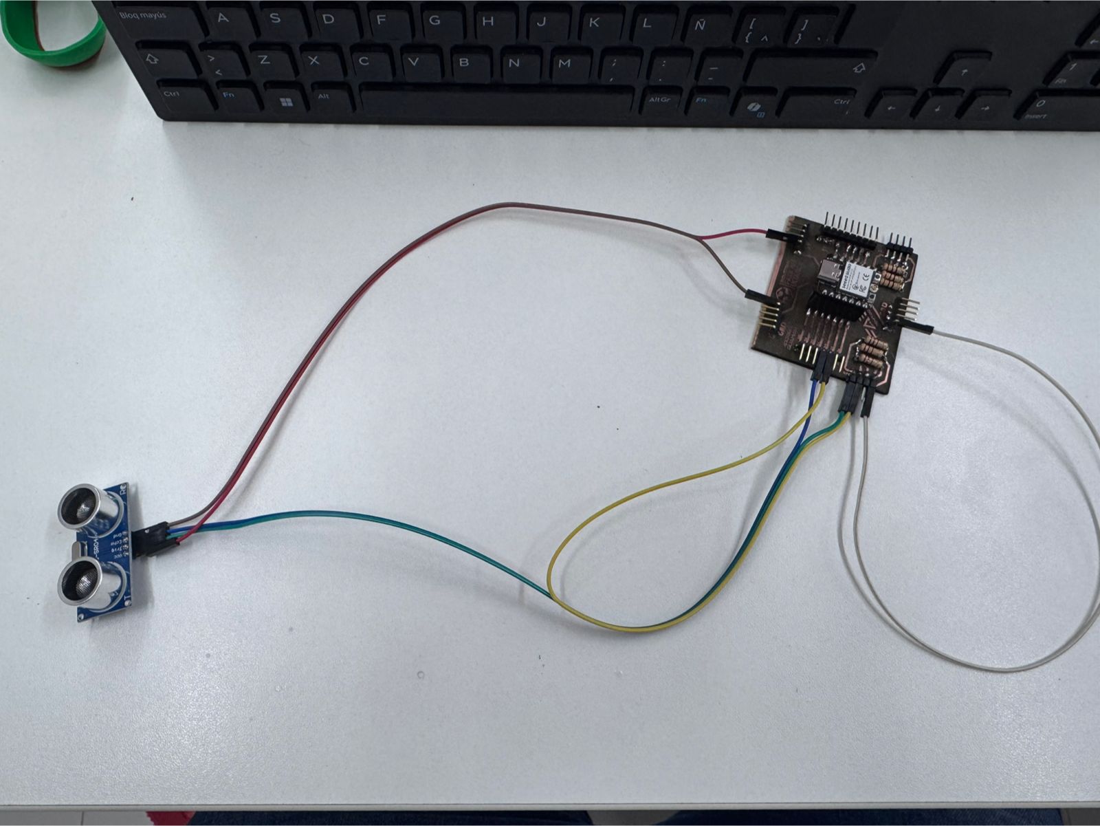
Serial.begin(115200): Sets the data rate. ESP32 chips standardly use 115200.digitalWrite(TRIG_PIN, HIGH): Starts the ultrasonic ping.pulseIn(ECHO_PIN, HIGH): This function waits for the Echo pin to go HIGH, starts a timer, and stops when it goes LOW.0.0343: Constant representing the speed of sound at sea level (343 m/s) in cm/us.division by 2: Accounts for the wave traveling to the object and back.Serial Plotter (Tools > Serial Plotter) shows a dynamic wave graph of the distance changes.The final connection used the HC-SR04 ultrasonic sensor connected to the XIAO ESP32-C3 through the custom PCB. The board organizes the power rails and signal pins, while the sensor provides the distance input used by the program. The connection follows the logic used in the code: VCC to 5V, GND to GND, TRIG to the trigger pin, and ECHO to the input pin through the protection/divider path on the PCB.
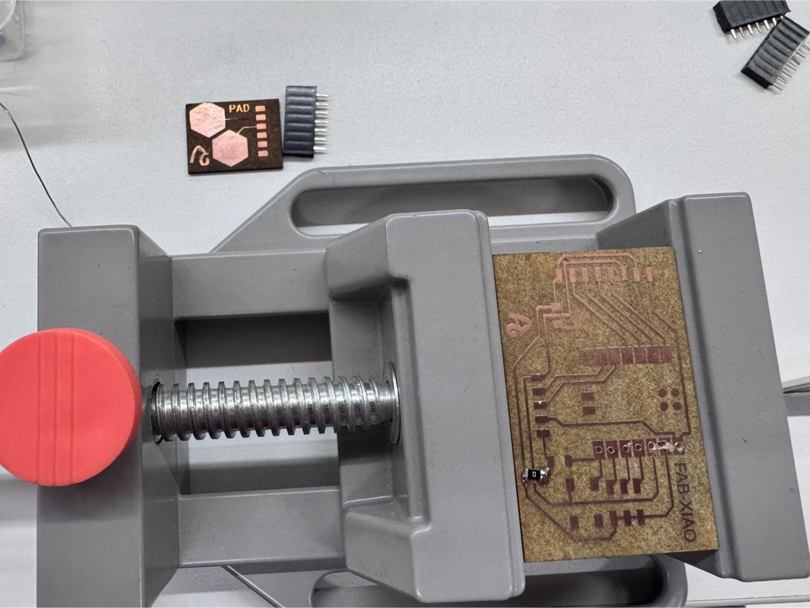
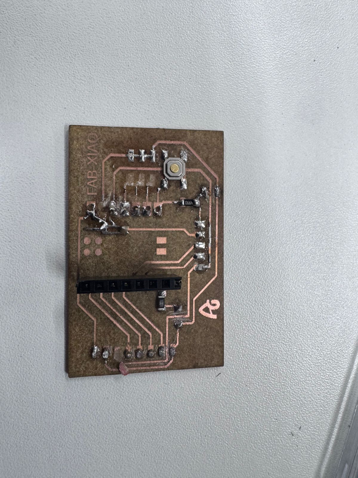
During the fabrication and assembly of the input device boards, the most difficult part was not only programming the ultrasonic sensor, but also obtaining a reliable PCB. Several boards presented physical failures after milling and soldering, especially lifted copper traces, accidental bridges between tracks, and short circuits.
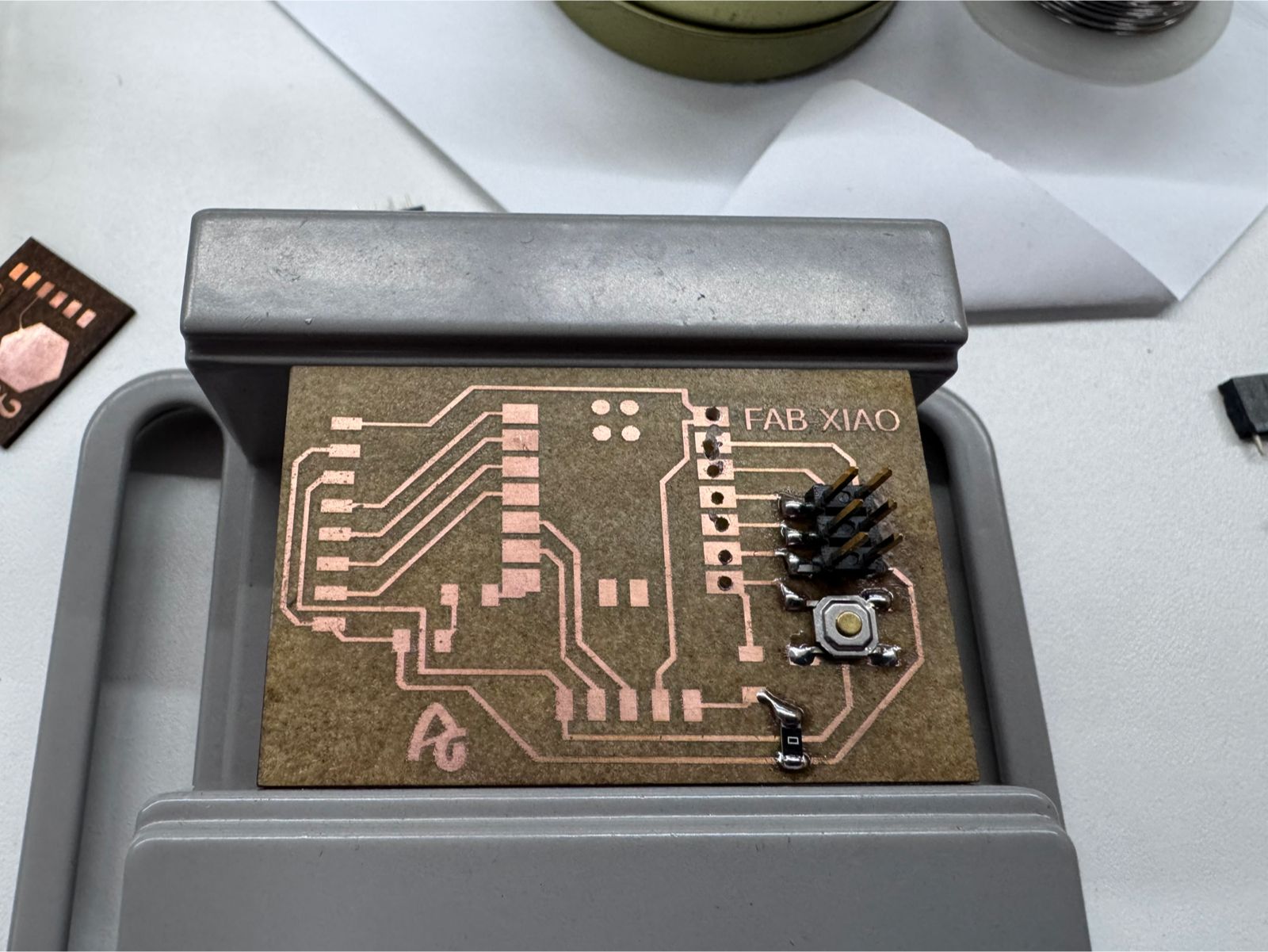
Some copper traces detached from the board during soldering and rework. This happened mainly in narrow tracks and pads that received too much heat or mechanical stress while correcting components. Once the trace lifted, the electrical path became weak or completely open.
I reduced the soldering time on each pad, used less force when adjusting headers, and checked continuity with a multimeter before connecting the microcontroller. In damaged areas, I reinforced the connection with solder bridges or jumper wire only when the repair did not create a risk of short circuit.
In some zones, the traces were very close to each other. During soldering, excess tin created unwanted bridges between adjacent tracks and pads. These track collisions produced short circuits that prevented the board from working correctly.
I inspected the board visually after every soldering step and used the continuity mode of the multimeter to detect shorts between power, ground, and signal lines. When a bridge appeared, I removed excess solder carefully and cleaned the area before testing again.
When trying to repair a damaged trace, the solder sometimes expanded toward nearby copper areas. This created new short circuits, especially near the pin headers and small SMD components.
The repair process had to be slower and more controlled. I tested each repaired section before powering the board, separated suspicious joints, and avoided connecting the XIAO board until the power rails were confirmed to be safe.
This problem showed me that PCB fabrication is a complete process, not only a design file. A board can look correct in the software, but the real result depends on milling quality, trace width, soldering temperature, component alignment, and electrical verification. For future boards I will leave more clearance between critical tracks, make pads stronger where connectors will be soldered, and test continuity before connecting the microcontroller. These failures were frustrating, but they helped me understand why inspection and debugging are part of electronics fabrication.
This assignment provided a comprehensive understanding of how input devices can be integrated into a microcontroller-based system to measure real-world variables and generate meaningful responses. Through the use of an ultrasonic sensor, it was possible to successfully capture distance data and translate it into a clear visual output using LEDs.
One of the key learnings from this process was the importance of hardware compatibility. The initial attempt using the XIAO ESP32C3 revealed challenges related to voltage levels and signal stability. Migrating to the Arduino Uno/Nano simplified the system significantly, allowing direct communication with the sensor and improving reliability during prototyping.
The project also highlighted the importance of signal processing. Although the ultrasonic sensor provides digital output, the information it carries is time-based and subject to noise. Implementing techniques such as averaging multiple readings proved essential to achieving stable and accurate measurements, especially in short-distance ranges.
From a programming perspective, the assignment reinforced the use of structured code, including modular functions, conditional logic, and real-time data monitoring through the Serial Monitor. The separation of the distance-reading function from the main loop improved code readability and scalability.
The development process demonstrated the value of iterative prototyping. Starting from a simple LED test, progressing to multiple LEDs, and finally optimizing to a two-LED system allowed gradual debugging and refinement. This step-by-step approach reduced complexity and ensured that each component worked correctly before integrating the full system.
In terms of application, the system successfully replicates a basic industrial sensing mechanism. The proximity-based LED logic simulates how sensors are used in conveyor belts and assembly cells to detect object presence, control movement, and ensure operational safety. This establishes a strong foundation for future developments in automation systems.
Additionally, the assignment fulfilled both the group and individual requirements. The group work enabled the analysis of sensor signals and their behavior, while the individual implementation demonstrated the ability to measure a physical variable and process it through a custom-built system.
Finally, this project reinforces the idea that effective engineering solutions often rely on simplicity, proper component selection, and iterative testing. The knowledge gained in this assignment can be directly applied to more advanced systems, including IoT integration, smart manufacturing, and real-time process control.