
Week 14
Molding and Casting
Designing a one-part mold, machining a wooden counter-mold, producing a silicone rubber mold, and casting a plaster piece.
1. Checklist
- ✅ Linked to the group assignment page and reflected on what I learned
- ✅ Reviewed the safety and material considerations for molding and casting
- ✅ Designed a 3D model for the mold in Autodesk Inventor
- ✅ Created a one-part mold based on the geometry and casting process
- ✅ Fabricated a wooden counter-mold using CNC machining
- ✅ Used CAM strategies for 3D roughing, 3D finishing, engraving and profile cutting
- ✅ Sanded and sealed the MDF counter-mold to improve surface quality
- ✅ Calculated the silicone rubber volume required for the mold
- ✅ Produced a silicone rubber mold from the machined MDF counter-mold
- ✅ Used the silicone mold to cast a plaster part
- ✅ Documented problems, solutions and process decisions
- ✅ Included design files and process evidence
- ✅ Included a hero shot of the counter-mold, mold and final casted object
2. Group Assignment
The group assignment for this week focused on reviewing safety data sheets for molding and casting materials, making and comparing test casts, and comparing printed molds with milled molds. This was important before developing the individual mold because it helped me understand the behavior of different materials and fabrication processes.
From the group work, I learned that the production method of the mold has a direct impact on the surface finish of the final casted part. For example, 3D printed molds can show the layer lines of the additive manufacturing process, while CNC machined molds can show toolpath marks if the finishing strategy and the tool selection are not correct.
This group comparison helped me decide that, for my individual work, I needed to pay attention to surface finish, sanding, sealing, tool selection, material porosity, and demolding strategy.
3. Introduction to Molding and Casting
Molding and casting is a manufacturing process used to reproduce shapes from an original model. In general, the process starts with a master model or counter-mold. From this, a mold is created. Then, a liquid or semi-liquid material is poured into the mold and allowed to cure or solidify. Once the material is solid, the final part can be removed from the mold.
This process is used in many industries because it allows the reproduction of complex geometries, textures and details. Depending on the application, molds can be made from different materials such as silicone rubber, metal, plaster, resin, wood, or food-safe materials.
| Type of mold | Common use | Main characteristic |
|---|---|---|
| Silicone rubber molds | Small objects, prototypes, art pieces and detailed surfaces | Flexible, easy to demold and capable of copying fine details. |
| Metal molds | Industrial production, injection molding and high-volume manufacturing | Durable, precise and suitable for repeated production cycles. |
| Food-grade molds | Chocolate, pastry, ice, candy and culinary applications | Made with materials that are safe for contact with food. |
| 3D printed molds | Rapid prototyping and low-cost testing | Fast to produce, but may show layer lines if not post-processed. |
| CNC machined molds | Precise molds, counter-molds and smooth surfaces | Good surface quality if the correct toolpaths and tools are selected. |
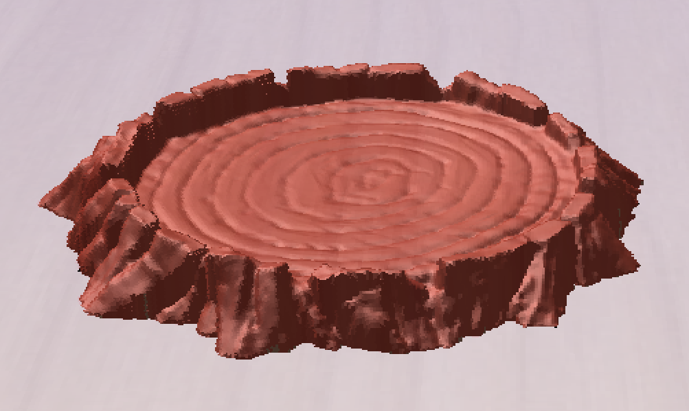
In this assignment, I designed a small organic object inspired by a tree trunk with subtle roots. The objective was to create a simple one-part mold but with enough surface detail to evaluate how well the mold and casting process could reproduce the original design.
4. Design Concept
For the individual assignment, I designed a tree trunk cut near its base, where subtle roots extend from the lower area. The object was intentionally designed to be simple enough for a one-part mold, but also detailed enough to test the quality of the molding and casting process.
The surface of the trunk includes circular wood rings and wood grain patterns. These details were important because they allowed me to evaluate whether the counter-mold, silicone mold and plaster casting could reproduce small design features from the original 3D model.
The design was created in Autodesk Inventor and exported as an STL file. The approximate diameter of the model is 10 cm. Since the geometry does not have complex undercuts, I decided to use a one-part mold.
5. Mold Strategy
The process selected for this assignment was to first machine a counter-mold in MDF using a CNC machine. Then, the counter-mold would be used to create a silicone rubber mold. Finally, the silicone mold would be used to cast a plaster part.
I used 12 mm MDF to fabricate the counter-mold. The CAM process was prepared in Aspire Vectric, where I reviewed the model dimensions, adjusted the machining strategy, configured the toolpaths and selected the tools.
One important design decision was not to use a rectangular box around the model. Instead, I created an offset around the contour of the trunk geometry, leaving approximately 10 mm around the model. This was done to reduce the amount of silicone rubber required for the mold.
This decision helped optimize material and resources because the silicone rubber would only occupy the area needed around the geometry, instead of filling a large rectangular volume.

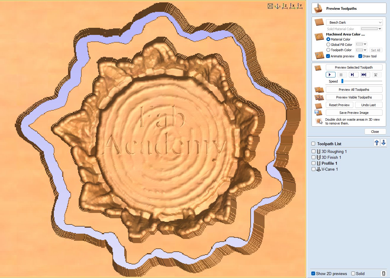
6. CNC CAM Process
The CAM process was divided into several operations. Each operation had a specific purpose, from removing material quickly to producing fine surface details and cutting the final contour of the counter-mold.
| Step | Toolpath | Tool | Purpose |
|---|---|---|---|
| 1 | 3D Roughing | 6 mm end mill, 2 flutes, upcut | Remove the largest amount of material from the 3D model in a robust and efficient way. |
| 2 | 3D Finish | 3 mm nose mill / ball nose tool | Create a finer surface and reproduce the details of the model, such as the roots and the wood grain patterns. |
| 3 | Engraving / V-carving | 60° V-bit | Machine the text “FAB ACADEMY 2026” on the surface of the trunk. |
| 4 | Profile Cut | 6 mm end mill | Cut the external profile of the counter-mold outside the contour line. |
The 3D roughing toolpath used a larger tool to remove material quickly. After that, I replaced the tool with a smaller nose mill for the 3D finish operation. This is important because smaller tools can reach more details and produce a smoother surface, although they also require more machining time.
Ball nose or nose mill tools are useful for 3D finishing because they help define curved surfaces and small details. In molding and casting, this is very important because any texture or toolpath mark left in the mold can be copied into the final casted part.
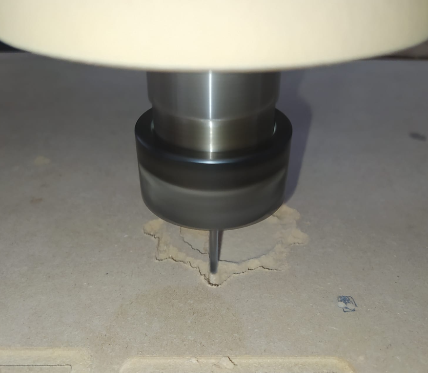
7. CNC Fabrication of the Counter-Mold
After preparing the toolpaths, I fabricated the counter-mold using the CNC machine. The MDF board had a thickness of 12 mm, which was enough for the depth and geometry of the tree trunk design.
During fabrication, I followed the toolpath sequence defined in Aspire Vectric. The roughing operation removed most of the material, the finishing operation improved the surface quality and details, the V-bit engraved the text, and the final profile cut released the counter-mold from the MDF board.
8. Surface Finish and MDF Sealing
Once the counter-mold was fabricated, I sanded it to remove imperfections and improve the surface quality. First, I used 180 grit sandpaper and then 280 grit sandpaper. This helped reduce rough areas and machining marks from the MDF surface.
Sealing the MDF was a very important step because MDF is a porous material. If the surface is not sealed, the silicone rubber can interact with the pores of the wood, creating defects, making demolding more difficult, or producing a poor surface finish.
For the sealing process, I prepared the following materials: high-solids sealer from WESCO as component A, catalyst as component B, a brush, nitrile gloves and a container for the mixture.
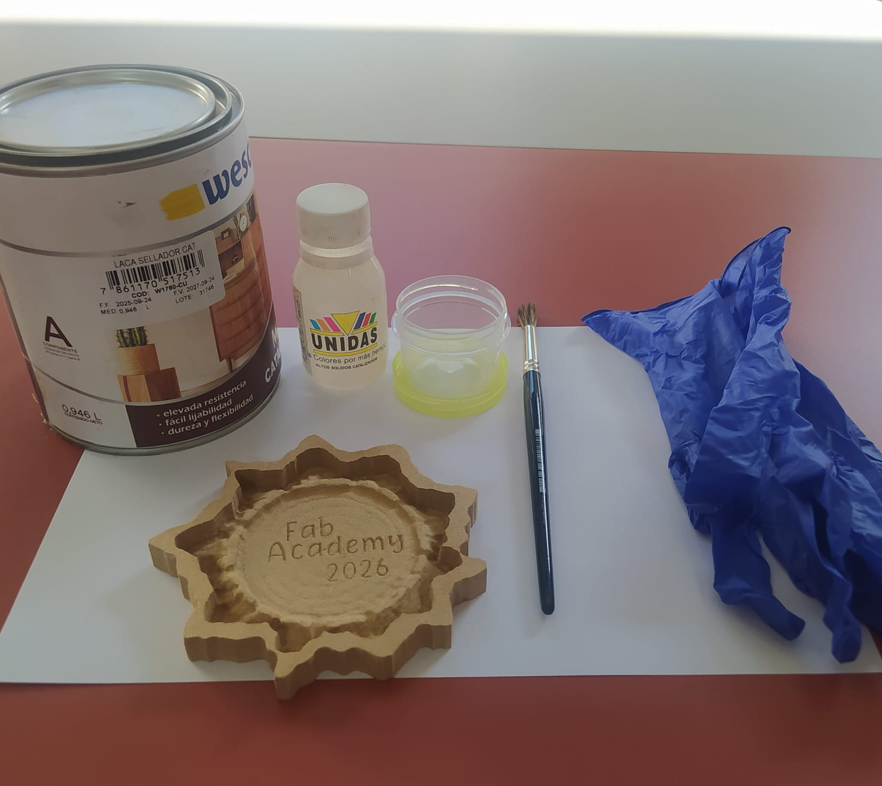
The mixture ratio was 10 parts of component A and 1 part of component B. After mixing both components well, I applied the sealer to the MDF surface using a brush. I applied between two and three coats, waiting approximately 1 to 2 hours between each coat.
This process helped seal the porosity of the MDF and created a better surface for the silicone rubber mold. After the sealer dried, I sanded the surface again using 320 grit sandpaper to make it smoother.
9. Silicone Rubber Mold Preparation
After the counter-mold was sealed and sanded, I prepared the materials for the silicone rubber mold. The materials used were silicone rubber as component A, catalyst as component B, a mixing container and nitrile gloves.
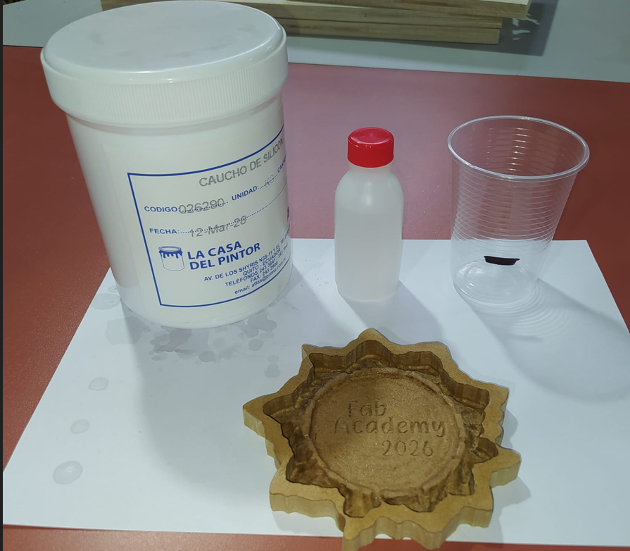
The mixture ratio for the silicone rubber was also 10 parts of component A and 1 part of component B, following the manufacturer's technical instructions.
Before mixing the silicone, I calculated the amount of material required. This was important because using too much silicone wastes material, but using too little silicone could leave the mold incomplete.
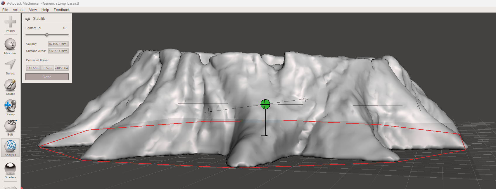
10. Silicone Volume Calculation
To calculate the silicone rubber volume, I used Meshmixer. First, I measured the volume of the original model. Then, I measured the volume of the geometry with the 10 mm offset. By subtracting one value from the other, I obtained the approximate volume required to fill the mold area.
| Measurement | Value | Conversion / Result |
|---|---|---|
| Original model volume | 97,495 mm³ | 97.495 ml |
| Volume with 10 mm offset | 146,708 mm³ | 146.708 ml |
| Difference | 49,213 mm³ | 49.213 ml of silicone rubber |
| 20% safety margin | +9.842 ml | To avoid missing material during pouring |
| Final estimated amount | 59.05 ml | Required silicone rubber volume |
Since 1 cm³ is equal to 1 ml, the calculated volume in cubic millimeters was converted to milliliters. I also added a 20% safety margin to avoid running out of material during the pouring process.
11. Pouring the Silicone Rubber
After calculating the amount of silicone rubber, I mixed component A and component B according to the manufacturer ratio. The mixture had to be homogeneous to ensure correct curing.
Once the mixture was ready, I poured it into the sealed MDF counter-mold. This process had to be done carefully and relatively quickly because the silicone starts reacting after the catalyst is mixed.
After pouring the silicone, I gently tapped the counter-mold on the surface. This helped air bubbles move upward and reduced the risk of internal bubbles affecting the final mold quality.
According to the manufacturer, the silicone rubber should be fully cured after approximately 48 hours. After this time, the mold can be removed from the counter-mold.
12. Demolding the Silicone Mold
After the silicone rubber cured, I carefully removed it from the MDF counter-mold. The sealing process helped make demolding easier because the MDF surface was less porous and the silicone did not attach strongly to the wood.
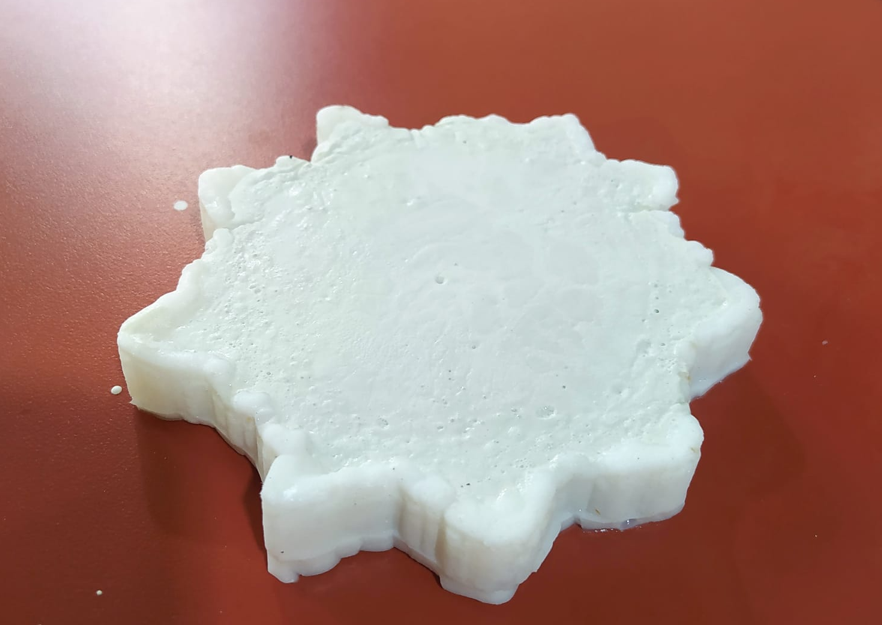
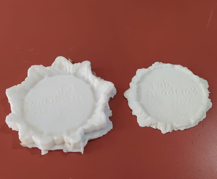
The result was a flexible silicone rubber mold that copied the geometry of the tree trunk, the roots, the surface details and the engraved text.
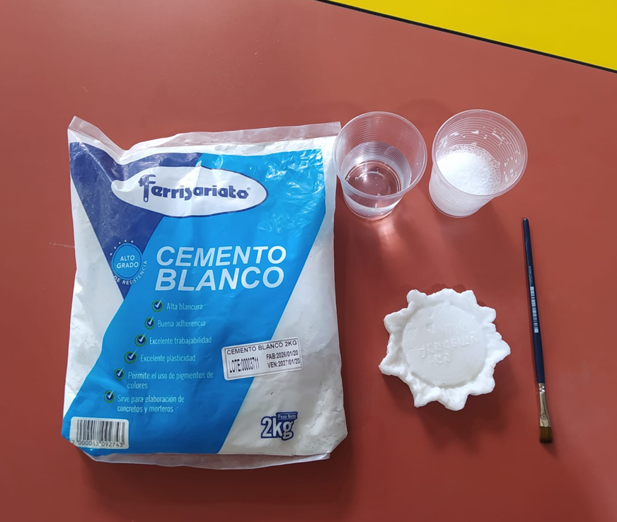
13. Casting with Plaster
After obtaining the silicone mold, I continued with the casting process. For the casting material, I used plaster because it is accessible, easy to mix, and suitable for testing the reproduction of the mold geometry.
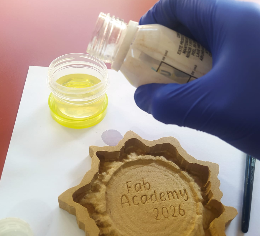
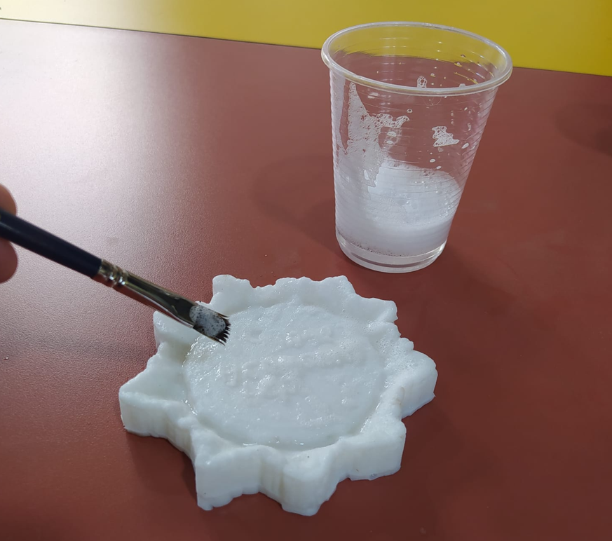
The materials used for this stage were plaster, water, a container, a brush and a homemade release agent. The release agent was prepared using liquid hand soap and a small amount of water.
Before preparing the plaster mixture, I applied the release agent to the silicone mold using a brush. This step was important because it made the demolding process easier and reduced the risk of breaking the casted piece.
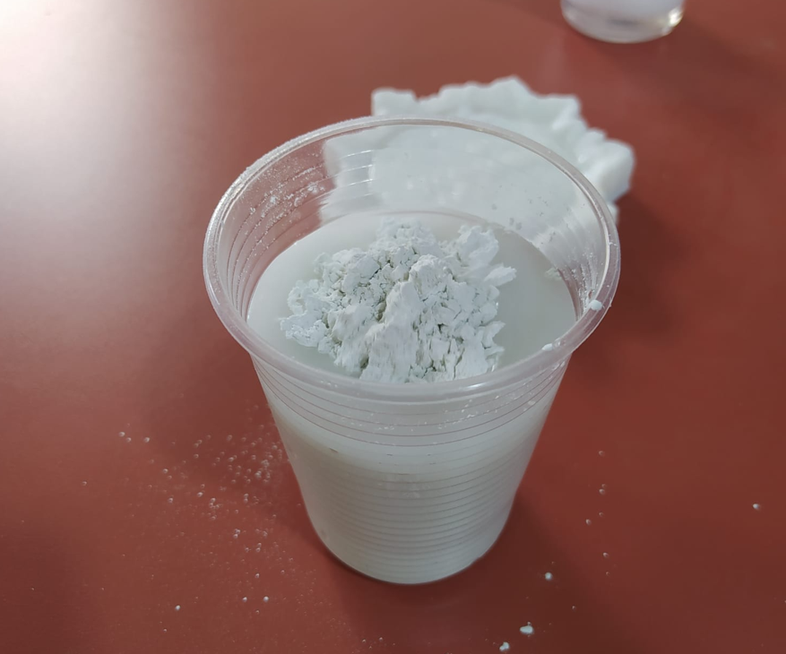
For the plaster mixture, I used approximately 1.5 parts of water and 1 part of plaster. The water was added first, then the plaster was added gradually while mixing. The final mixture needed to be homogeneous and have a viscosity similar to yogurt.
14. Pouring and Curing the Plaster
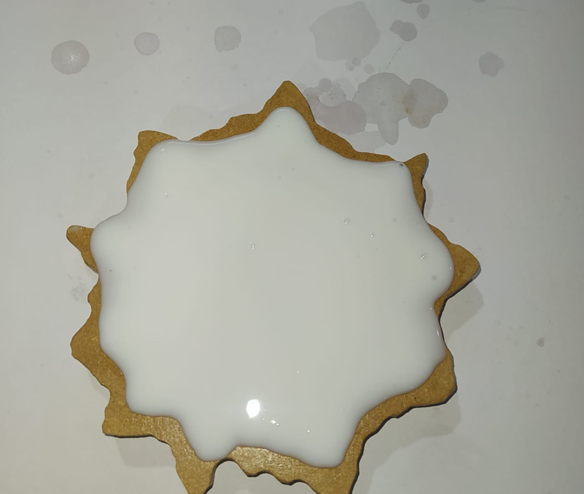
Once the plaster mixture was ready, I poured it into the silicone mold. The mold already had the release agent applied. During the pouring process, I gently tapped the mold to help the material enter all the details and to move trapped air bubbles toward the surface.
After filling the mold, I left the plaster to dry. The estimated drying time was between 12 and 24 hours, depending on the amount of material, environmental conditions and mixture consistency.
15. Final Demolding and Result
After the curing time, I demolded the plaster part carefully. The flexibility of the silicone rubber mold and the use of the release agent made this process easier.
The final part reproduced the general geometry of the tree trunk, the root details and the surface features. This confirmed that the mold was able to transfer the main characteristics of the original design into the casted plaster piece.
16. Problems and Fixes
| Problem | Cause | Solution / Learning |
|---|---|---|
| MDF porosity | MDF is a porous material and can absorb or interact with liquid materials. | I sealed the counter-mold with high-solids sealer and catalyst, applying several coats and sanding the surface after drying. |
| Possible toolpath marks | CNC machining can leave marks depending on the tool and finishing strategy. | I used a 3D finishing toolpath with a smaller nose mill and sanded the surface to improve the finish. |
| Air bubbles in silicone | Mixing and pouring the silicone can trap air inside the material. | I tapped the counter-mold gently after pouring to help bubbles rise to the surface. |
| Material shortage risk | Using only the exact calculated volume could cause the mold to be incomplete. | I calculated the required volume and added a 20% safety margin before preparing the silicone mixture. |
| Possible breakage during plaster demolding | Plaster can be fragile, especially if the mold holds onto the part. | I applied a homemade release agent before pouring the plaster and removed the part carefully after curing. |
| Loss of small details | Small surface details depend on tool size, mold quality and casting material flow. | I used a finer finishing tool and tapped the mold during casting to help the plaster reach detailed areas. |
17. Design Rules and Process Considerations
Molding and casting requires thinking about the complete workflow from the beginning. The design must not only look good in the CAD software; it must also be manufacturable, moldable, castable and demoldable.
- A one-part mold is easier to fabricate and use, but the geometry must avoid undercuts that would prevent demolding.
- The tool diameter limits the level of detail that can be machined in CNC.
- A smaller finishing tool can reproduce more detail but increases machining time.
- Walls should have enough draft or soft angles to make demolding easier.
- The angle between the lower part of the mold and the model geometry must be considered to avoid areas that the tool cannot reach.
- Porous materials such as MDF must be sealed before using them with liquid mold materials.
- The amount of molding material should be calculated before mixing to avoid waste.
- Release agents are useful to protect the mold and reduce the risk of breaking the casted part.
18. Material Technical Summary and Datasheets
Three main materials were used during the molding and casting process: WESCO Maderlac Catalyzed Sealer for preparing and sealing the MDF counter-mold, a two-component RTV silicone rubber for producing the flexible mold, and white cement for casting the final part. The following summary presents the most relevant technical characteristics from the available product datasheets and relates them to the practical process documented in this assignment.
| Material | Technical characteristics | Application in the assignment | Important technical note |
|---|---|---|---|
| WESCO Maderlac Catalyzed Sealer / Primer | Two-component alkyd-amino sealer with approximately 38–42% solids, satin finish, theoretical coverage of approximately 10–11 m²/L at 25 µm, touch-dry time of 10–15 minutes, sanding time of 15–20 minutes, and a mixture life of approximately 5–8 hours at 25°C. | Applied to the CNC-machined MDF counter-mold to reduce porosity, improve the surface finish, and prevent the silicone rubber from penetrating or adhering strongly to the wood fibers. | The WESCO technical sheet specifies a preparation ratio of 20 parts component A to 1 part component B. The surface must be clean, dry and free of dust before application, and adequate ventilation and personal protective equipment are required. |
| Two-component RTV silicone rubber | Pourable, condensation-cure, room-temperature-vulcanizing silicone rubber designed for mold making. The reference SILASTIC RTV-3110 base is white, has low mixed viscosity, reproduces fine details, and cures into a flexible rubber suitable for demolding simple geometries. | Used to create the flexible negative mold from the sealed MDF counter-mold. The material was mixed manually, poured directly into the cavity, and lightly tapped to help release trapped air. | The original silicone was supplied locally by La Casa del Pintor Ecuador without a visible manufacturer or model number. Therefore, the attached SILASTIC RTV-3110 datasheet is included as a comparable technical reference. The reference sheet supports a 100:1 base-to- catalyst ratio when used with DOWSIL 4 Catalyst; the experimental material used in this assignment was also prepared at approximately 100 parts base to 1 part catalyst. |
| White cement | Super-white Portland cement intended for decorative, artistic and ornamental finishes, as well as mortars and concrete. It provides good adhesion, cohesiveness, workability and plasticity, and is compatible with conventional pigments and construction materials. The product complies with ASTM C150 and Ecuadorian standard NTE INEN 152. | Used as the rigid casting material poured into the silicone mold to produce the final tree-trunk piece and reproduce the principal geometry and surface details. | The technical sheet recommends mixing the dry components first and adding only the minimum water required to obtain adequate workability. It also recommends removing trapped air and beginning moist curing between 1 and 4 hours after placement, extending the curing process for up to 28 days when full cement performance is required. |
The silicone and white cement datasheets are used as technical references for materials with equivalent composition and application. The silicone container used during the assignment did not identify an exact manufacturer or commercial model, while the white cement datasheet corresponds to a comparable super-white Portland cement available in Ecuador.
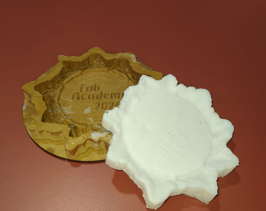
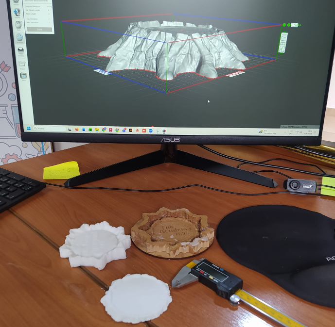
19. Dimensional Validation and Accuracy Comparison
The following image is the hero shot of this assignment. It presents the complete molding and casting workflow in a single composition, including the original CAD model, the CNC-machined MDF counter-mold, the silicone rubber mold, the final white cement cast, and the dimensional verification performed with a caliper.
To validate the accuracy of the molding and casting workflow, I compared key dimensions from the original CAD model, the CNC-machined mold, and the final cast part. Since the geometry includes subtle roots and surface details, I selected the same representative measurement points in all stages in order to keep the comparison as consistent as possible. For this validation, I used two main reference dimensions: the maximum diameter and the total height of the part.
The original dimensions were taken directly from the digital model, while the machined mold and final cast were measured physically using a caliper. This comparison helps to understand the overall dimensional fidelity of the process and reveals the small deviations introduced by CNC machining tolerance, tool diameter, sanding, material behavior, and the casting process itself.
| Reference dimension | Original CAD model | CNC machined mold | Final cast part |
|---|---|---|---|
| Total height | 11.2 mm | 11.0 mm | 11.1 mm |
| Maximum diameter | 103.0 mm | 101.0 mm | 102.0 mm |
| Comparison | Dimension | Difference vs. CAD | Approx. error |
|---|---|---|---|
| CNC mold vs. CAD | Total height | -0.2 mm | 1.79% |
| CNC mold vs. CAD | Maximum diameter | -2.0 mm | 1.94% |
| Final cast vs. CAD | Total height | -0.1 mm | 0.89% |
| Final cast vs. CAD | Maximum diameter | -1.0 mm | 0.97% |
The results show that the final cast remained very close to the original digital design, with dimensional deviations below 1 mm in height and about 1 mm in diameter. These differences are acceptable for this molding and casting workflow and confirm that the process reproduced the original geometry with good accuracy.
Small variations are expected because of several factors: CNC calibration, tool diameter and machining tolerance, sanding after machining, sealing layers applied on the MDF surface, the flexibility of the silicone mold, and the natural behavior of the white cement/plaster during curing. Even with those variables, the final result demonstrates a reliable dimensional transfer from the CAD model to the cast part.
20. Reflection
This reflection includes what I learned from my individual molding and casting process, and also what I learned from the group assignment comparison between different molding and casting methods.
- I learned that the design of the object must be planned according to the molding and casting process, not only according to its visual appearance.
- A one-part mold is simpler to produce, but the geometry must be carefully designed to avoid undercuts and demolding problems.
- The offset around the model helped reduce the amount of silicone rubber required, which is important for optimizing material and resources.
- CNC tool selection is very important. A larger end mill is useful for roughing, while a smaller nose mill is better for surface details.
- Surface finish is critical because any toolpath mark, roughness or imperfection can be transferred to the silicone mold and then to the final casted part.
- MDF is a porous material, so sealing it before pouring silicone rubber was necessary to improve the mold quality and make demolding easier.
- Mixing ratios must be followed carefully. Incorrect ratios can affect curing time, final hardness and the quality of the mold or casted part.
- Measuring or calculating the required material before mixing avoids waste and reduces the risk of not having enough material to complete the mold.
- Adding a safety margin to the calculated silicone volume was useful because the process can require slightly more material than the exact theoretical volume.
- Tapping the mold after pouring is a simple but useful technique to help air bubbles rise and reduce defects in the mold and casted part.
- The release agent was important during the plaster casting process because it helped remove the final part without breaking it.
- The curing times must be respected. Silicone rubber and plaster both require time to reach the correct state before demolding.
- I learned that molding and casting requires patience because there are several waiting stages: sealing, drying, curing and final demolding.
- From the group assignment, I learned that the fabrication method used to create a mold has a direct impact on the quality of the final casted part.
- In 3D printed molds, the layer lines from the additive manufacturing process can be visible. If the mold is not post-processed, these lines can later appear in the silicone mold and in the casted object.
- To improve a 3D printed mold, it is possible to sand the surface and apply lacquer, filler primer, resin, or another surface treatment to reduce the layer marks.
- In CNC machining, the quality of the mold depends strongly on the toolpath strategy, tool diameter, step-over, finishing pass and surface preparation.
- When machining a mold, it is important to consider design rules for molding and casting, such as wall angles, demolding direction, tool access and the relationship between the bottom of the mold and the model geometry.
- The group comparison helped me understand the difference between printed and machined mold surfaces, and how each process requires different post-processing decisions.
- Overall, this assignment helped me understand how digital fabrication, material preparation and casting techniques can be combined to reproduce a physical object with specific surface details.