The process
Group assignment:
01: Lab's safety
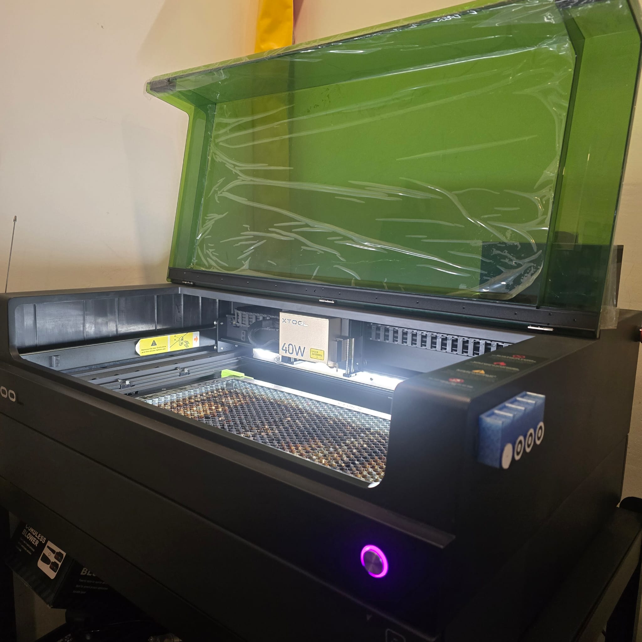
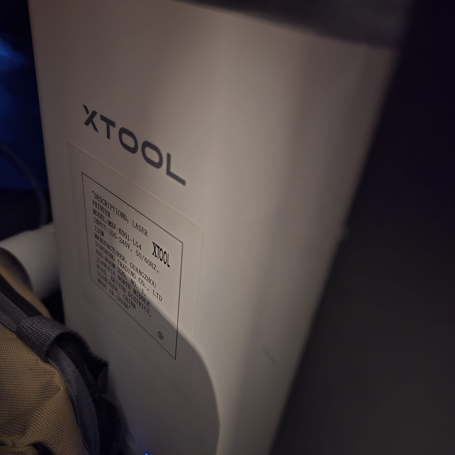
01| We are using the XTool S1 laser 40W
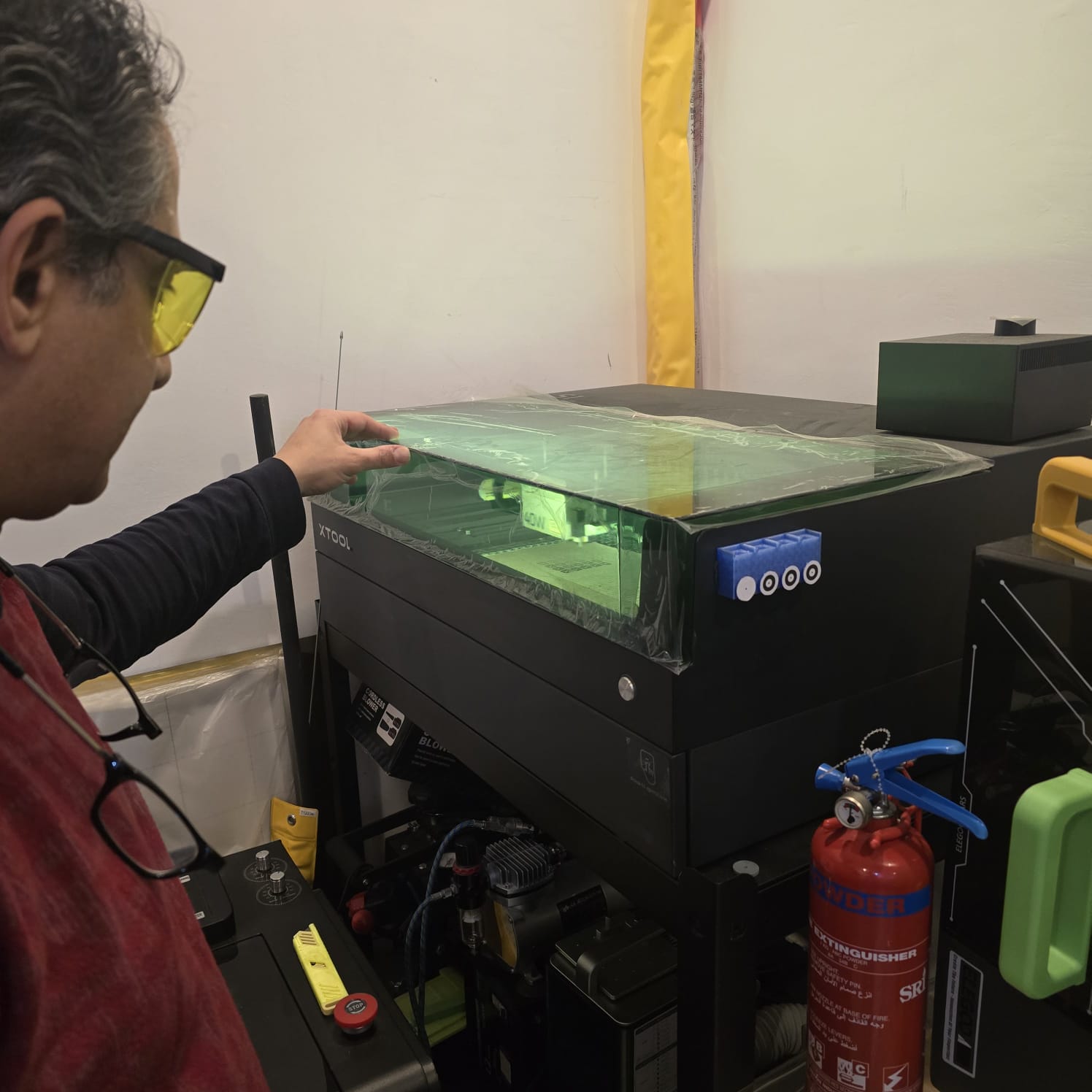
02| Wearing goggles and keeping a fire extinguisher close to us while someone keeps an eye on the device as long as it's working
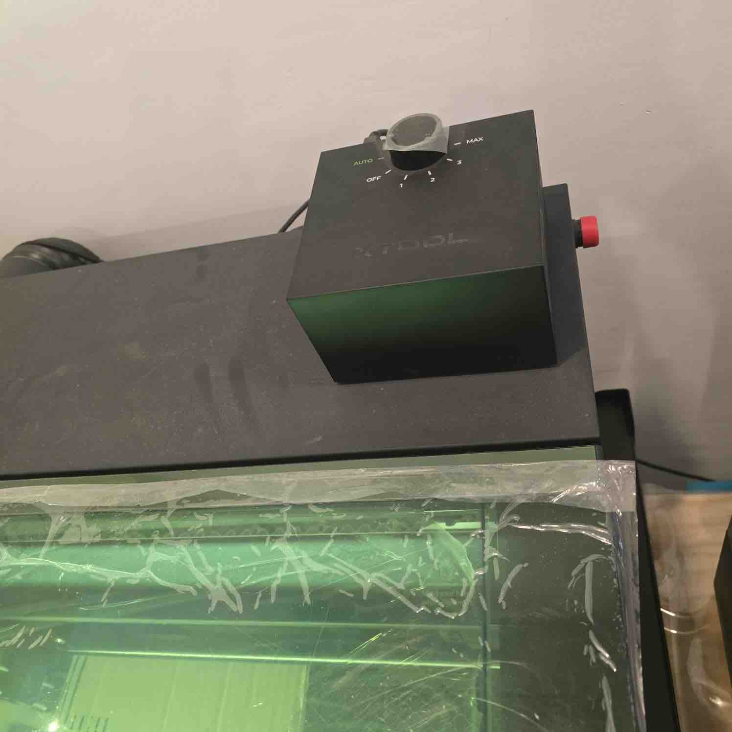
03| Using air assist to blow air on the cutting path and make sure the smoke is moved to the filter faster
04| We also use the xTool filter connected to the laser machine to make sure smoke and gases are treated immediately
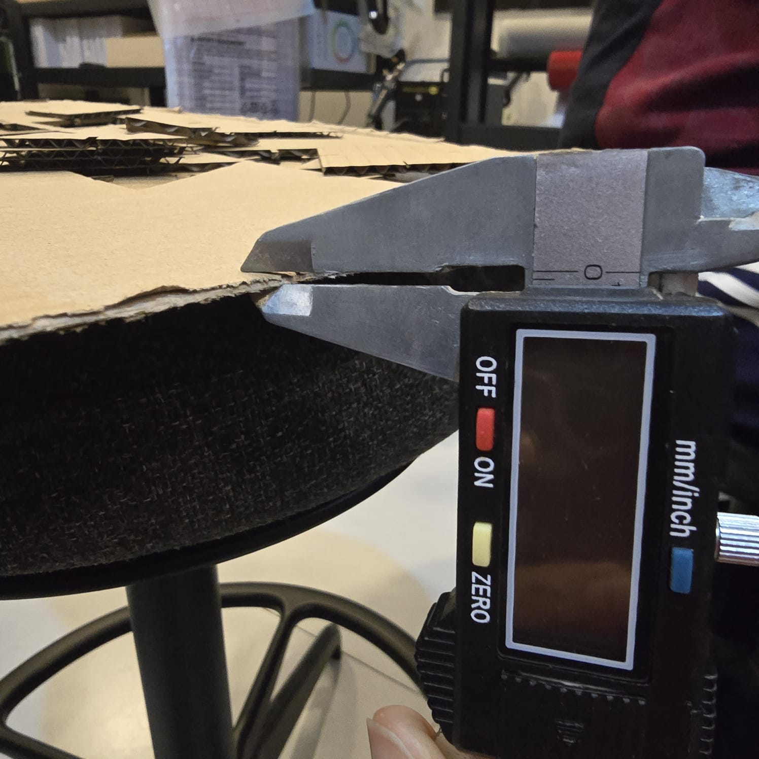
05| We used a cardboard 2mm
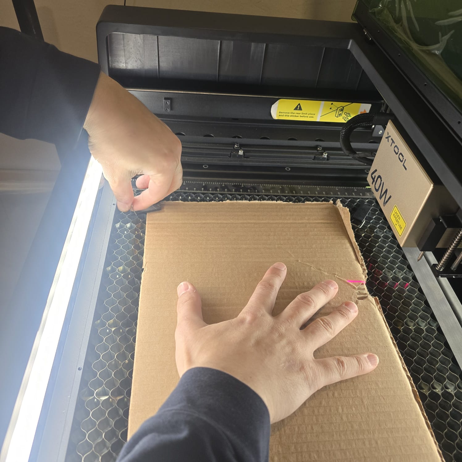
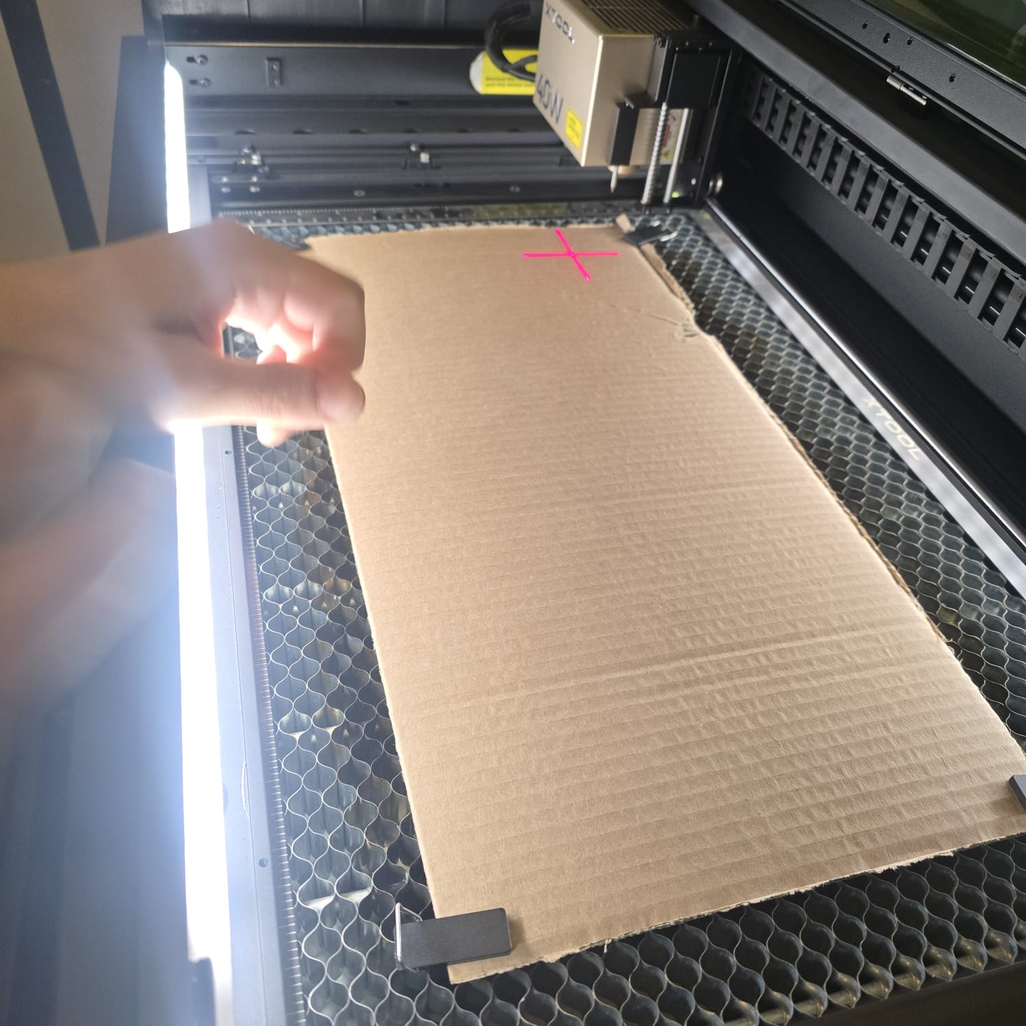
06| Fixing the cardboard on the bed to make sure it does not move during the cut
07| Having the tool check the height of the material used on xTool
- Feedback: It was not difficult to get to know xTool.
- Challenge: Using cardboard increases the risk of burning and fire, but it's the most environmentally friendly material, in addition to being cheap for training and practice.
02: Characterize lasercutter's
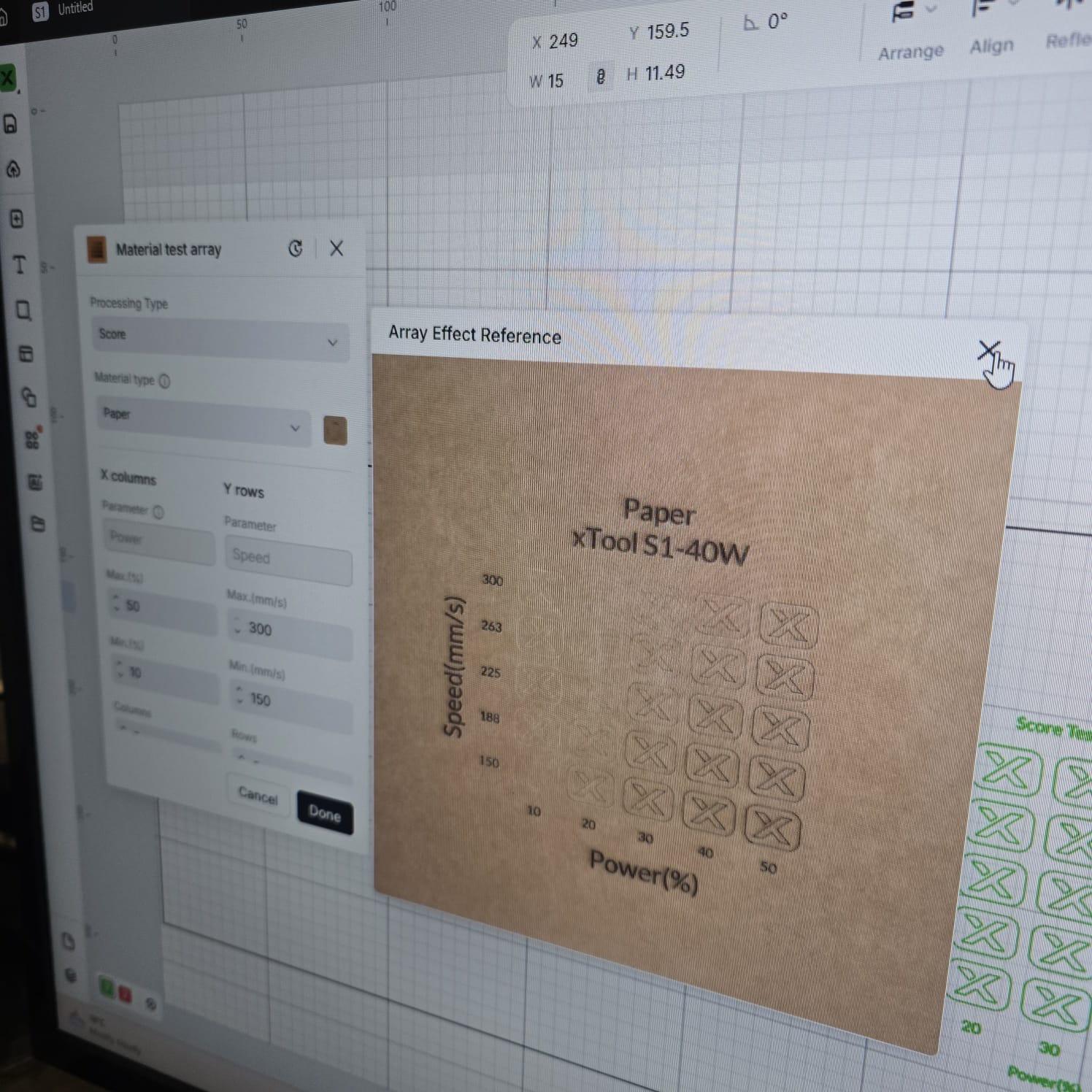
01 | Testing the scoring guide on paper
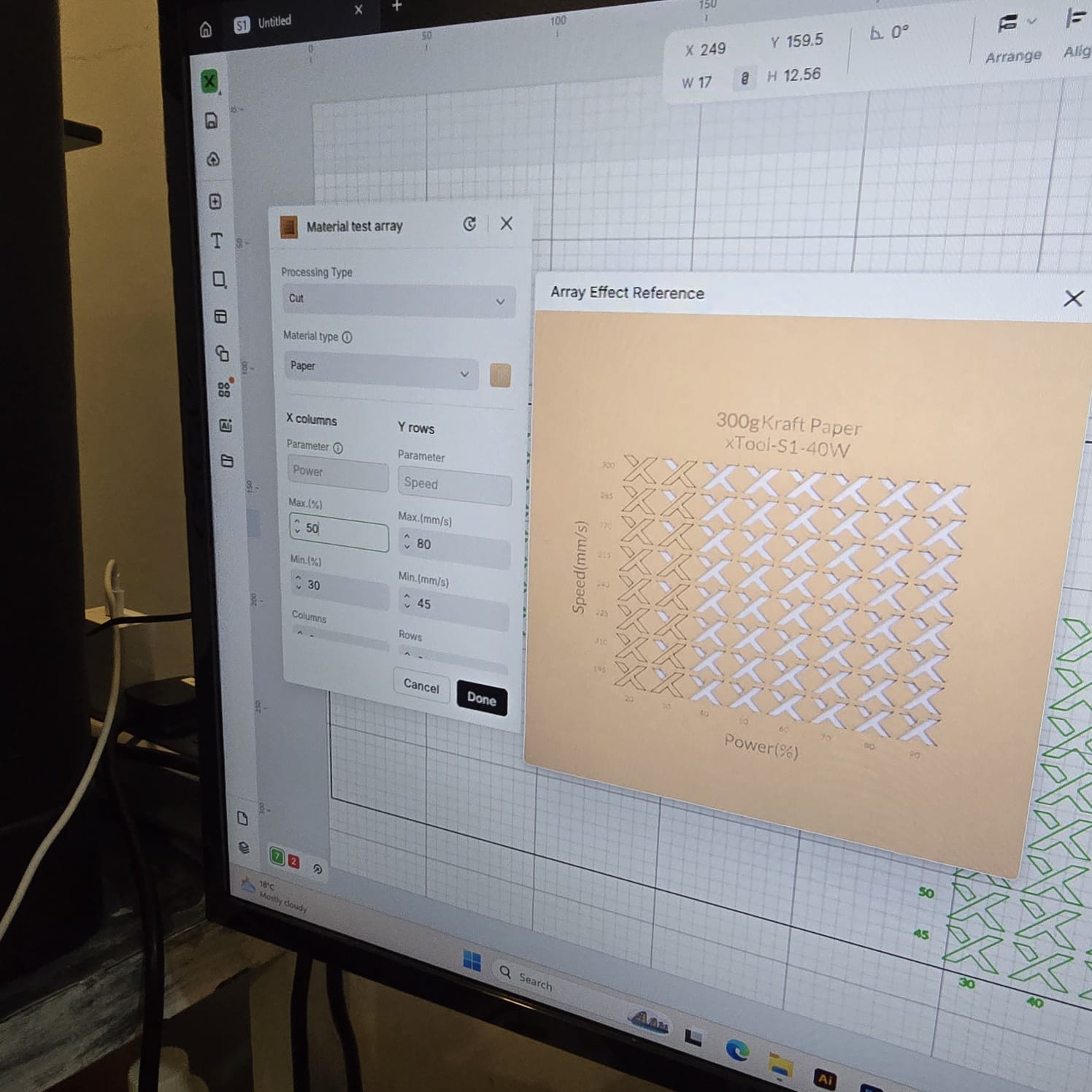
02| Testing the cut guide on paper
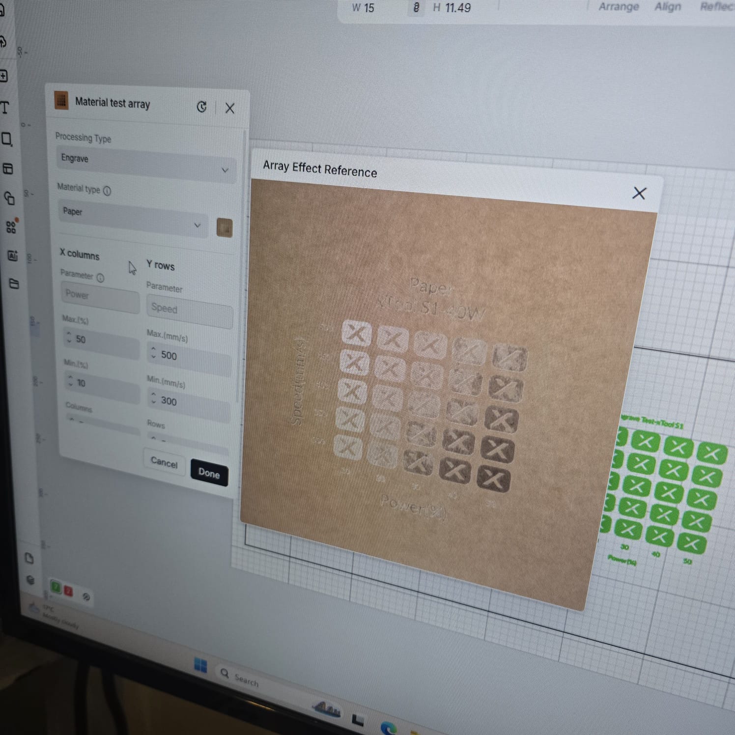
03| Testing the engraving guide on paper
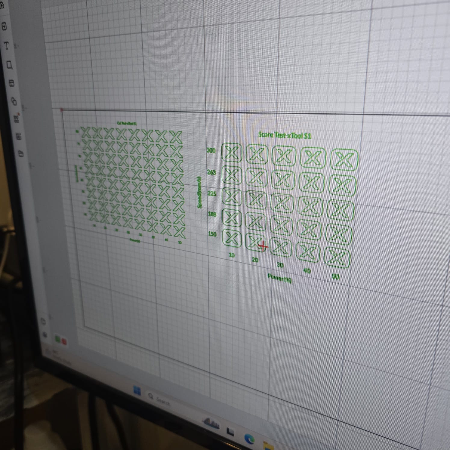
04| Aligning the designs on the print space as it was defined
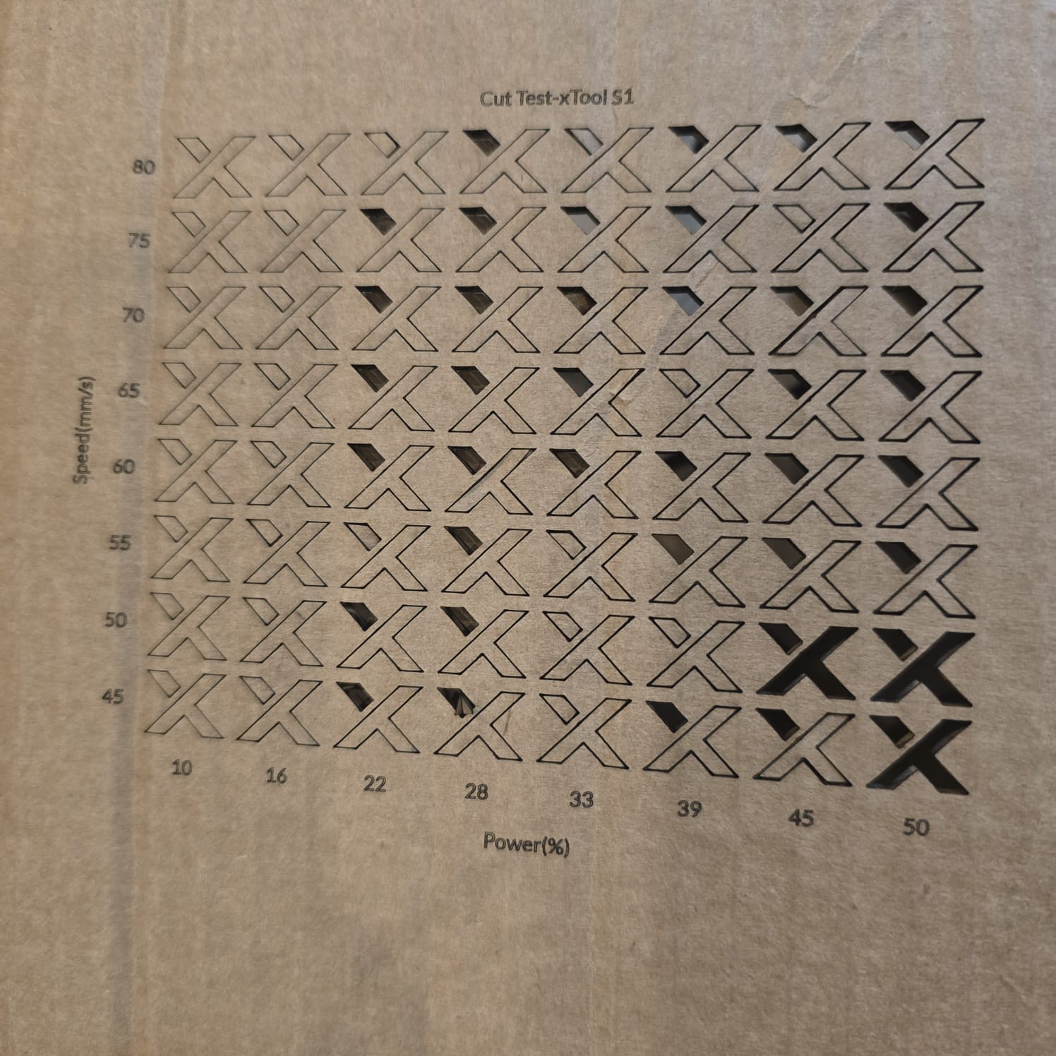
05| The results of cutting were clean; best power was between 45% and 50% and speed was between 45 and 50 (mm/s)
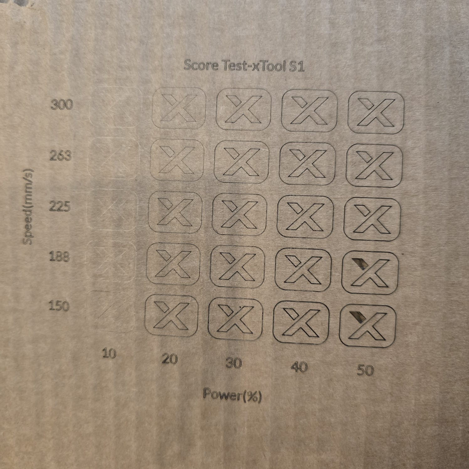
06| The results of scoring were clean; best at a power of 45% and a speed of 150 (mm/s)
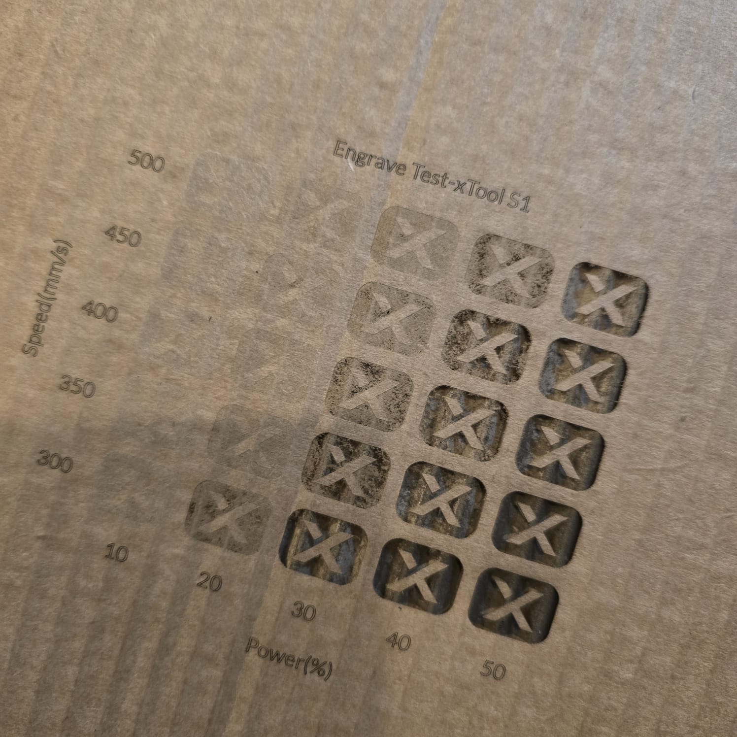
07| The results of engraving were clean; best at a power of 40%–50% and a speed of 300–350 (mm/s)
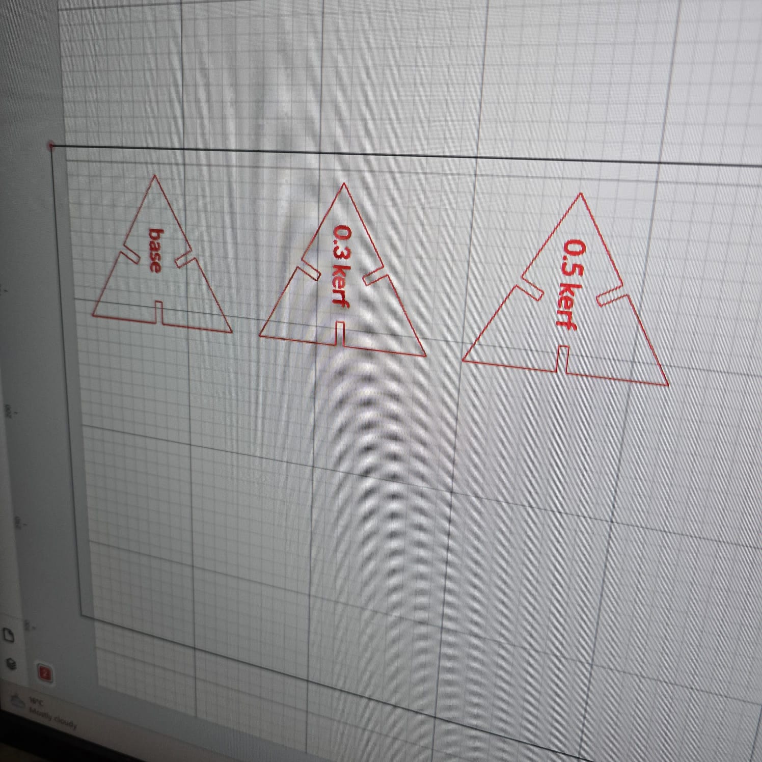
08| I designed triangles and compared the cut with different kerfs: 0, 0.3, 0.5
09| Even visually, the difference between the kerfs is clear
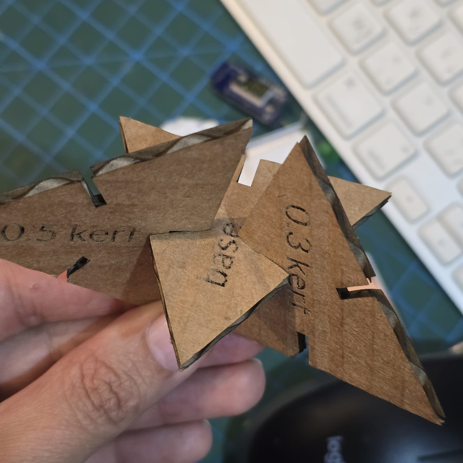
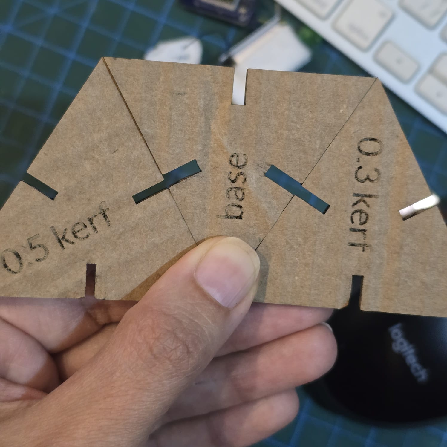
10| While fixing the pieces, the joints were too tight at 0.5 kerf and loose at a kerf of 0.
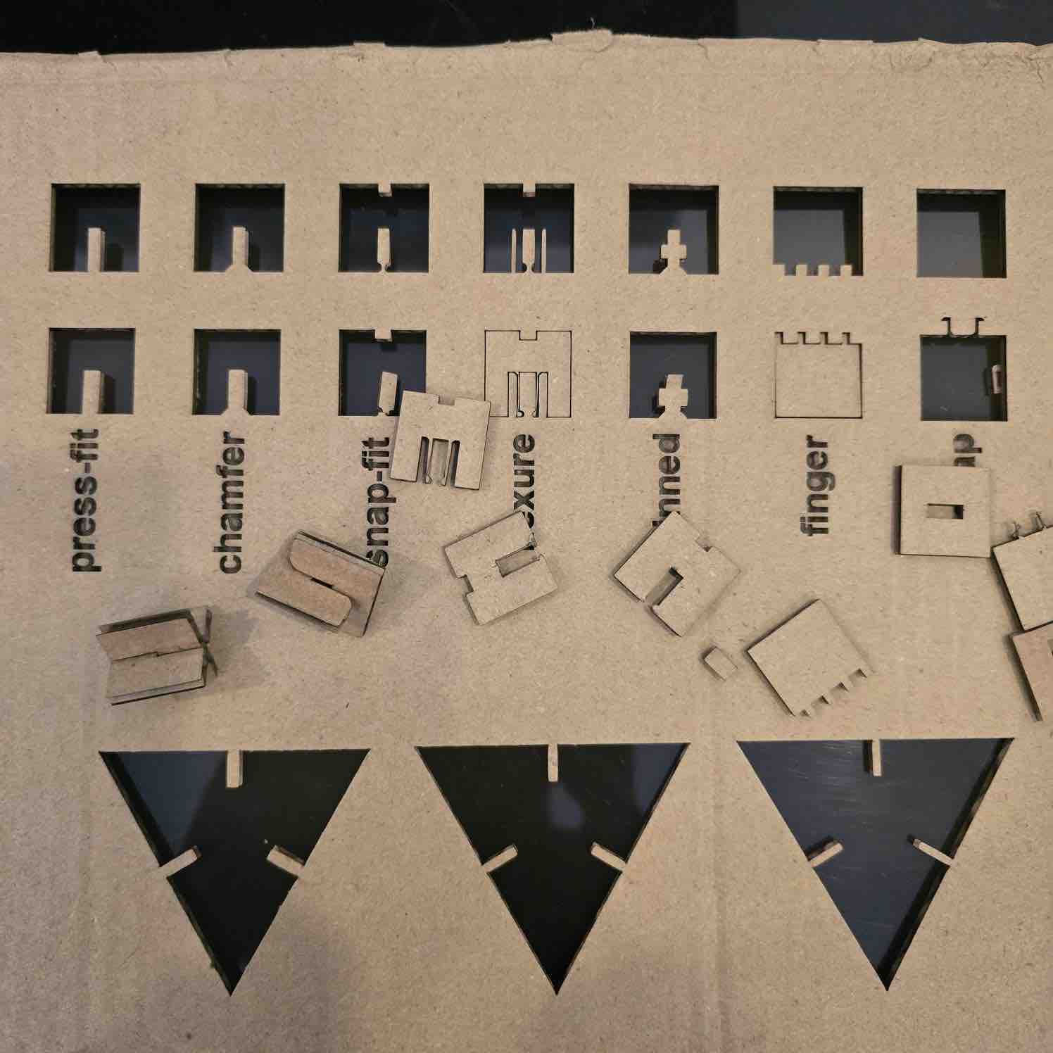
11| We also tested the joints
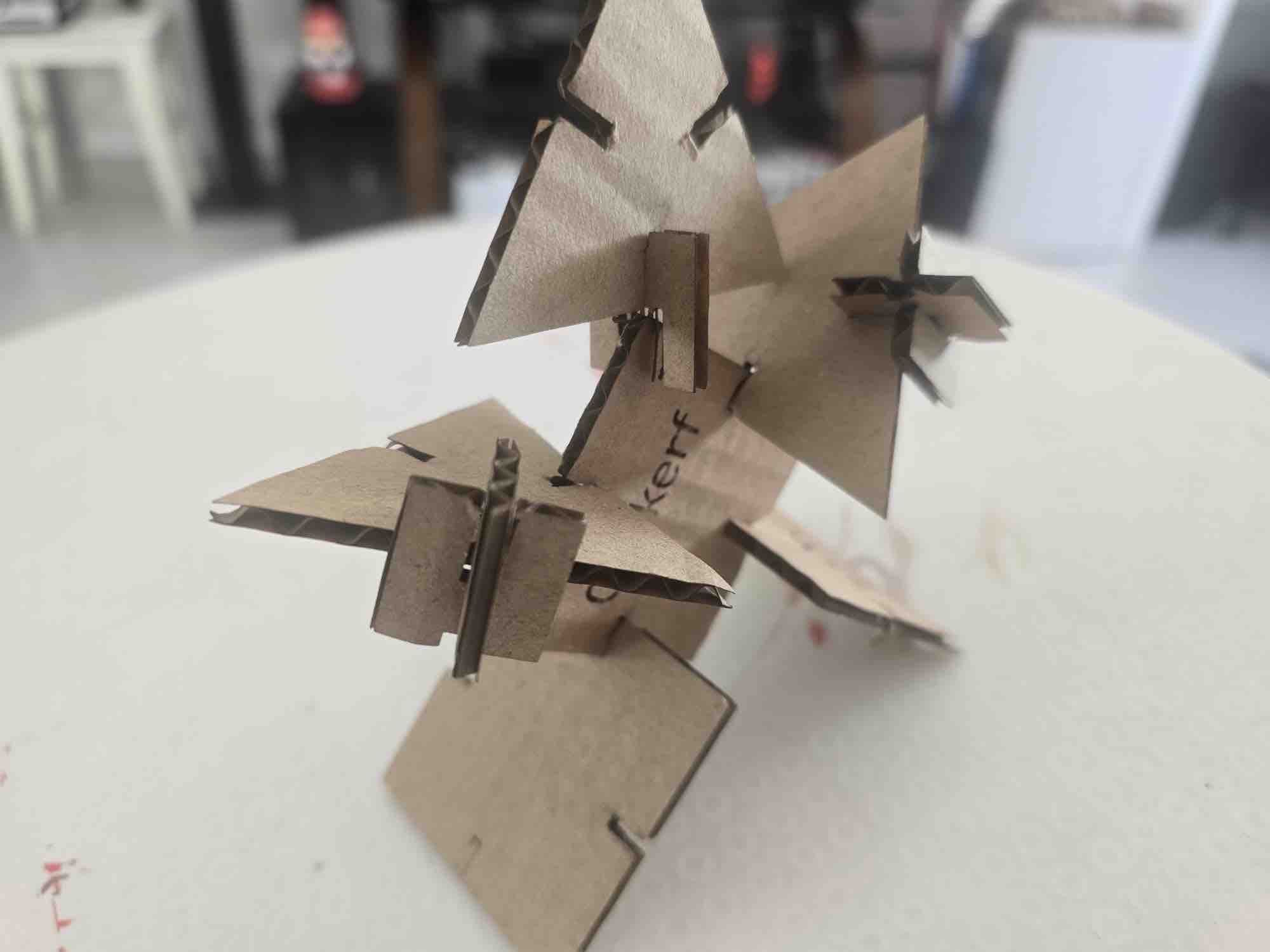
12| I used the different shapes and sized and trying to assember a tree but it looks more like a man 😅
- Feedback: The design rules will help a lot in any project — for our setup, the sweet spot was a kerf of 0.4 mm.
- Challenge: The cardboard had a bend in the middle, which can affect the performance of the laser cut.
Individual assignment
I also have basic experience designing some of the items I need for my work, especially designing and printing medals and honour plaques.
Option 01: Parametric Design on FreeCAD
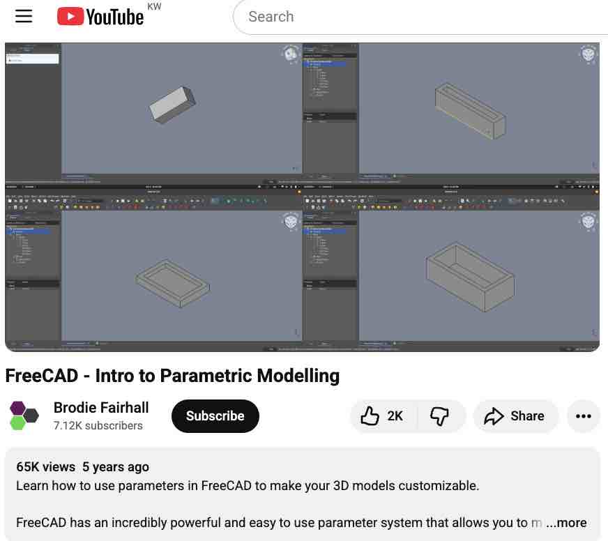
01 | I followed this tutorial to create a parametric design
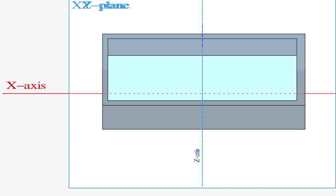
02| I added a pad to the X-Y plate and a pocket on the top surface
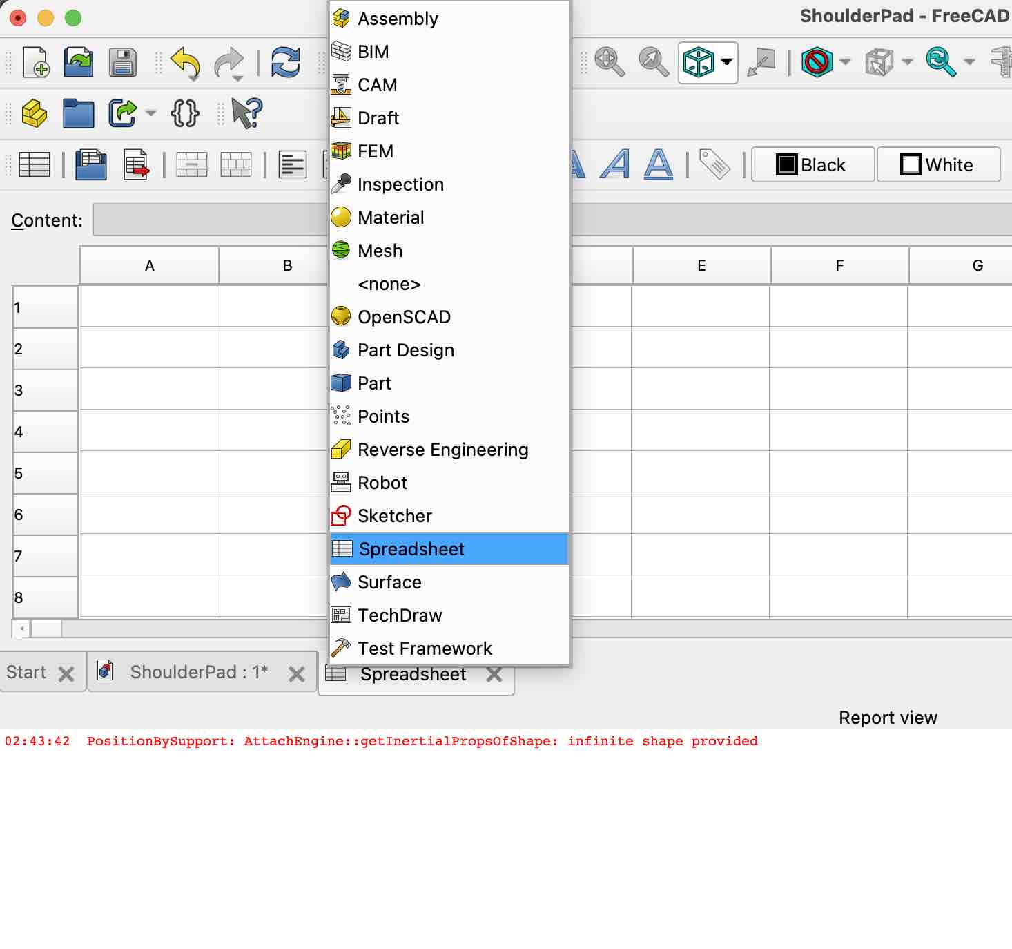
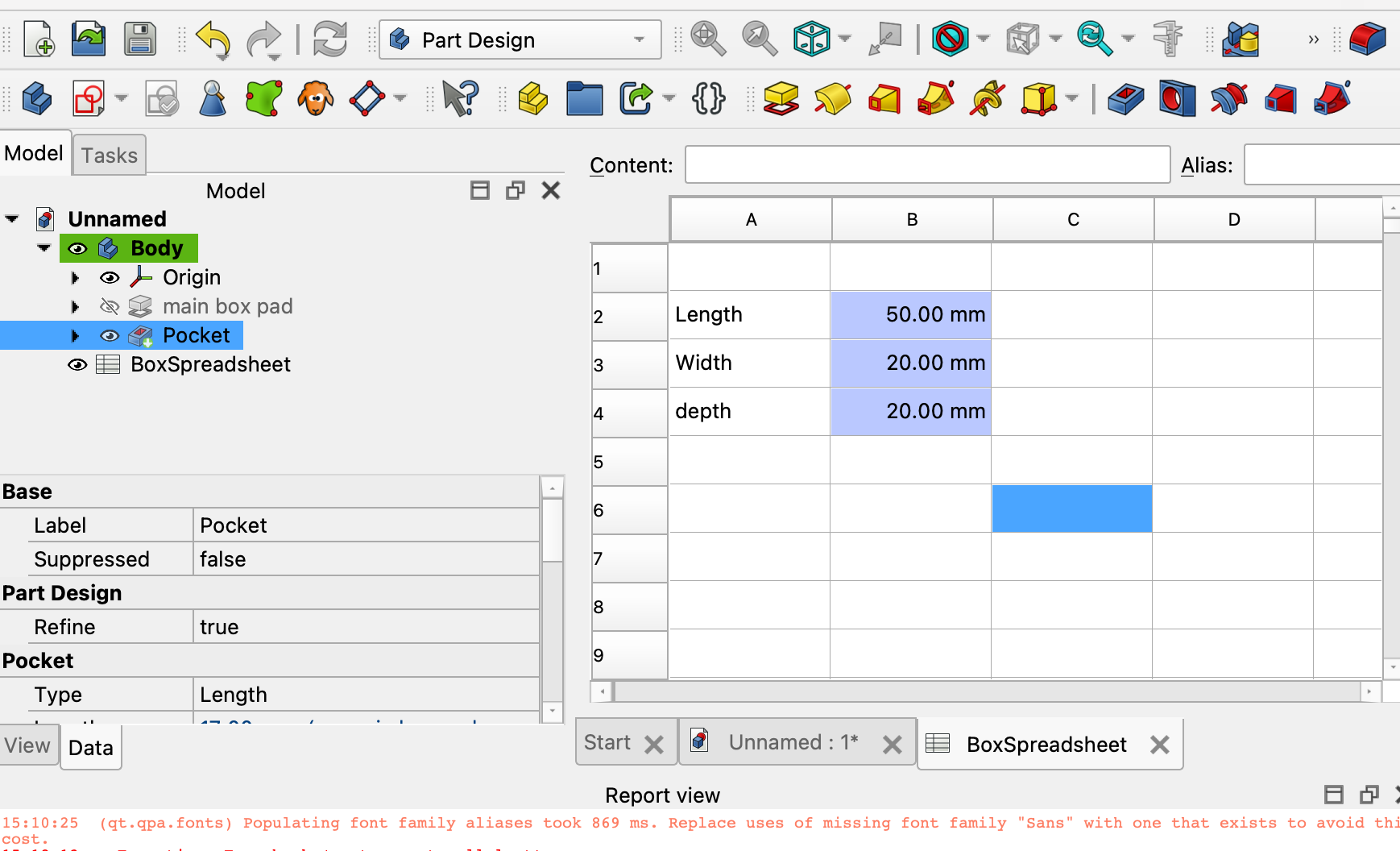
03| I created a spreadsheet to connect main values of length, width and depth
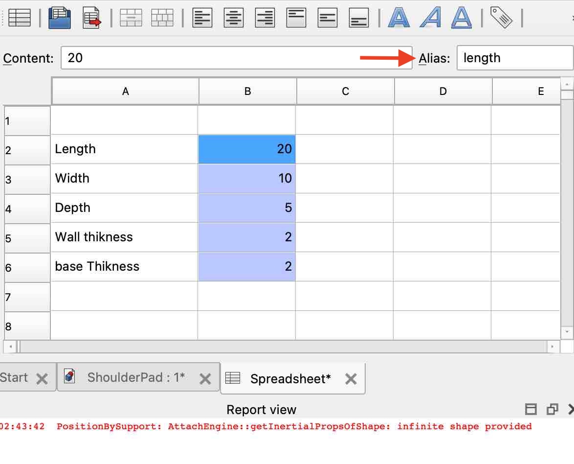
04| I added alias names to the values of length, width and depth
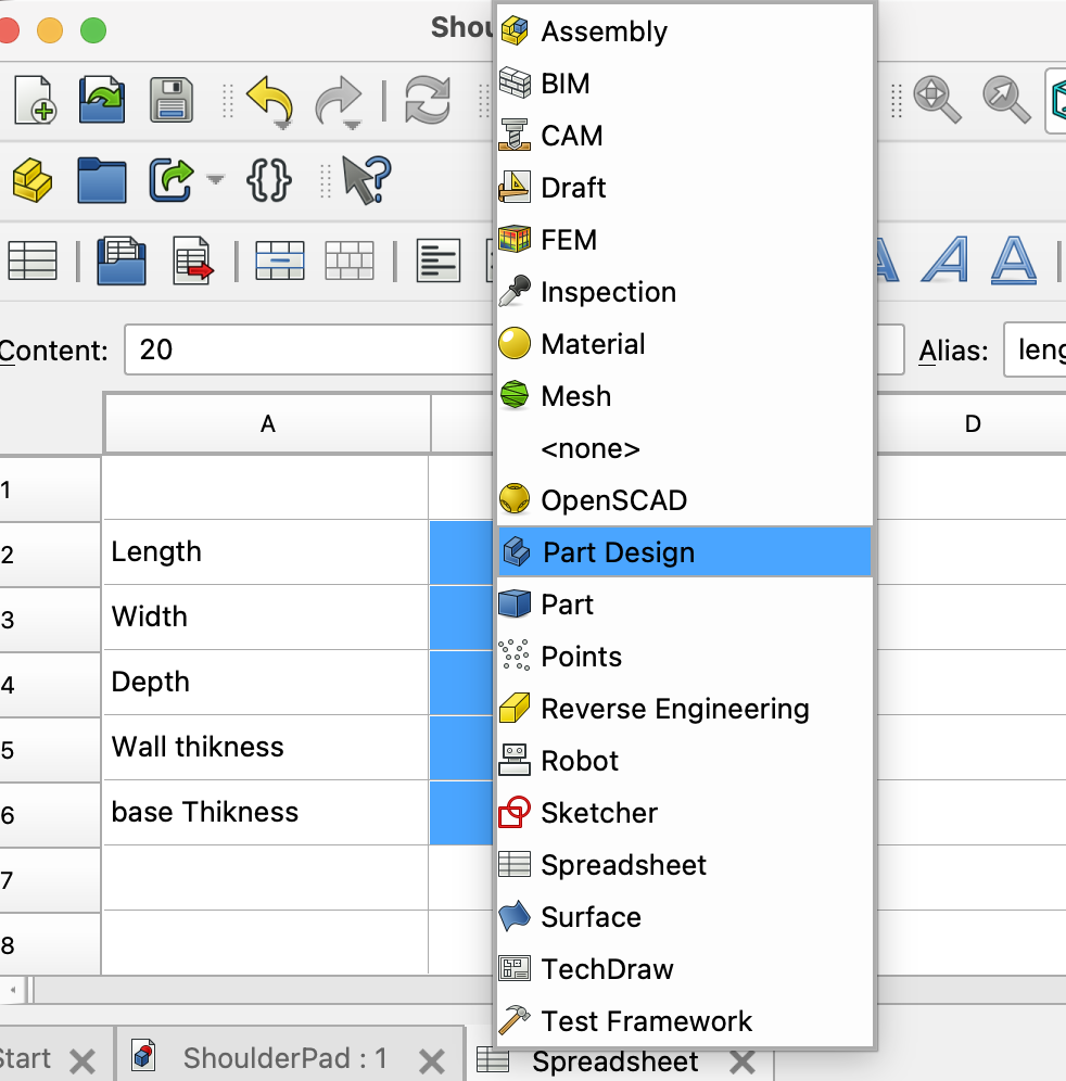
05| I switched to the Part Design page
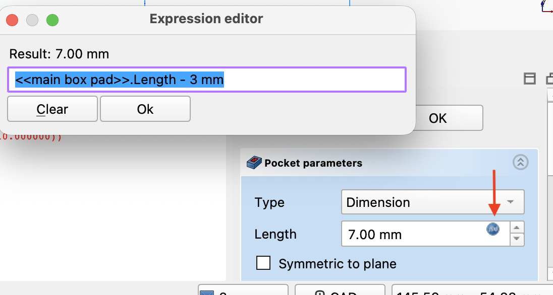
06| I added equations on the box to reference the values on the spreadsheet by their alias name
07| Then I changed the values on the spreadsheet to see how they would be applied.
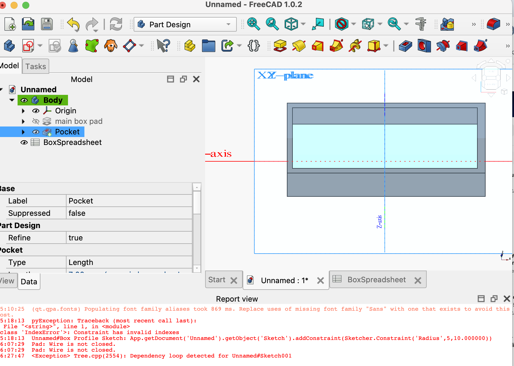
08| The dimensions of the box changed as expected, but the reference for the pocket added on top did not propagate.
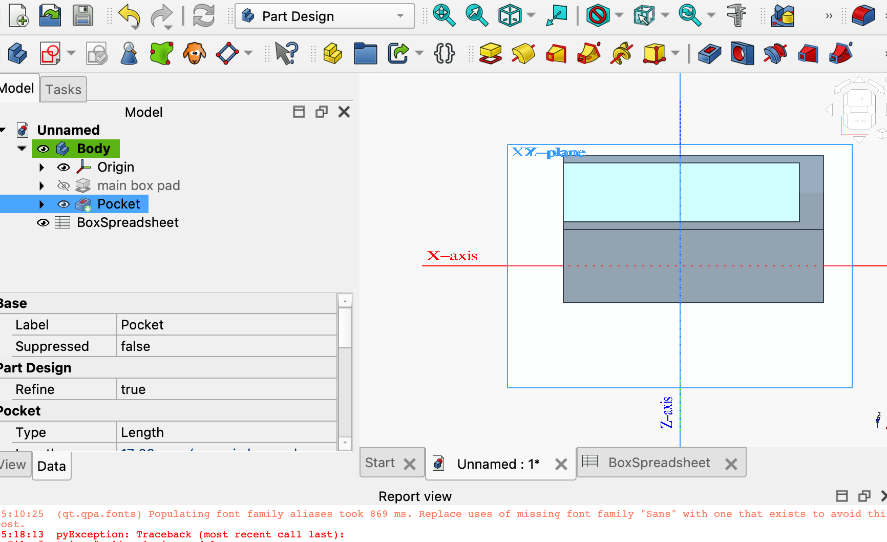
09| Side-by-side view — the box scales with the spreadsheet but the pocket stays anchored to the original dimensions, which is what I need to fix on the next pass.
- Feedback: There are many nice features in FreeCAD and it seems interesting. The parametric design was interesting and I can see how valuable it is in future projects
- Challenge: As a new IDE, the learning curve is very challenging and I really don't have much time to learn right now. I am planning to keep using it for a while before I try Fusion.
02: Vinyl Cut
We are already using the cutter to create the stickers we give away to all teams participating in WRO Kuwait
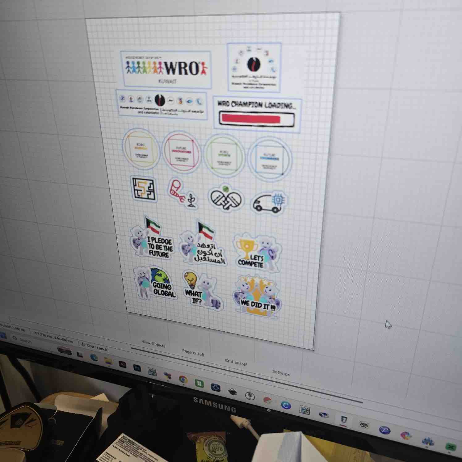
01 | The design is made in Canva, exported as PDF, and imported to the SignMaster application on Windows where I start defining the cut areas and the control around each shape.
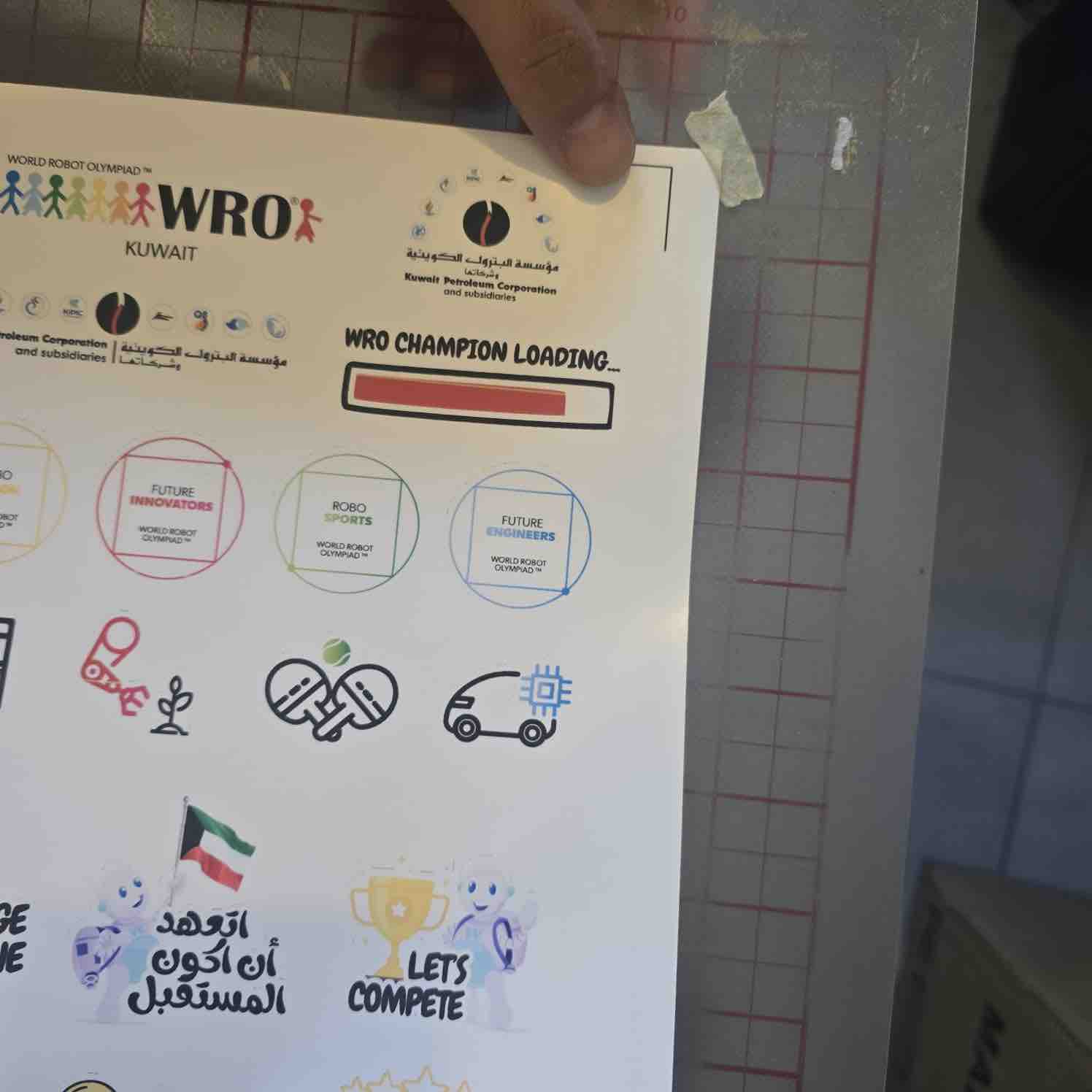
02| After printing the stickers we fix them on the cutting mat — the cutter's starting point is defined by the additional black registration marks on the sticker sheet.
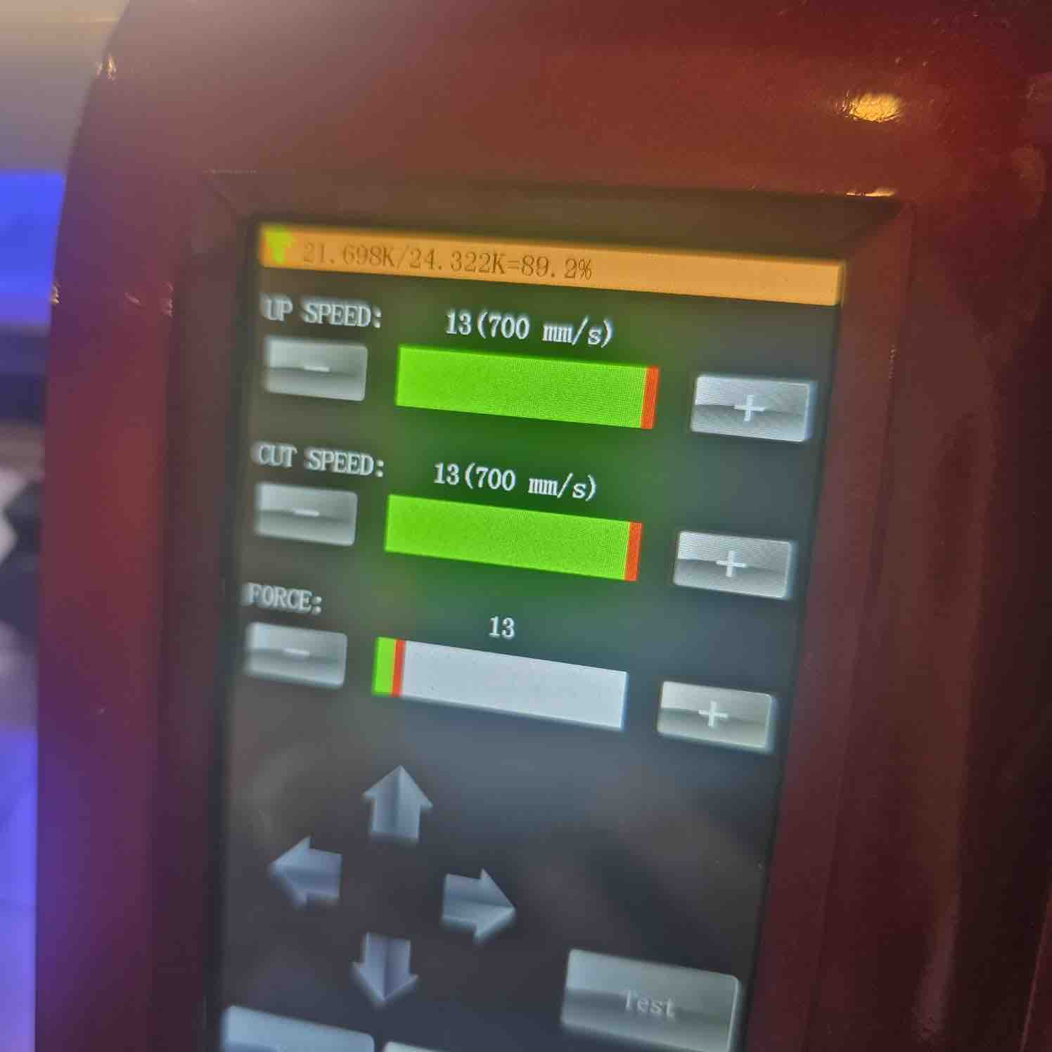
03| The settings of the cutter and defining the force to make sure the stickers are not completely cut off
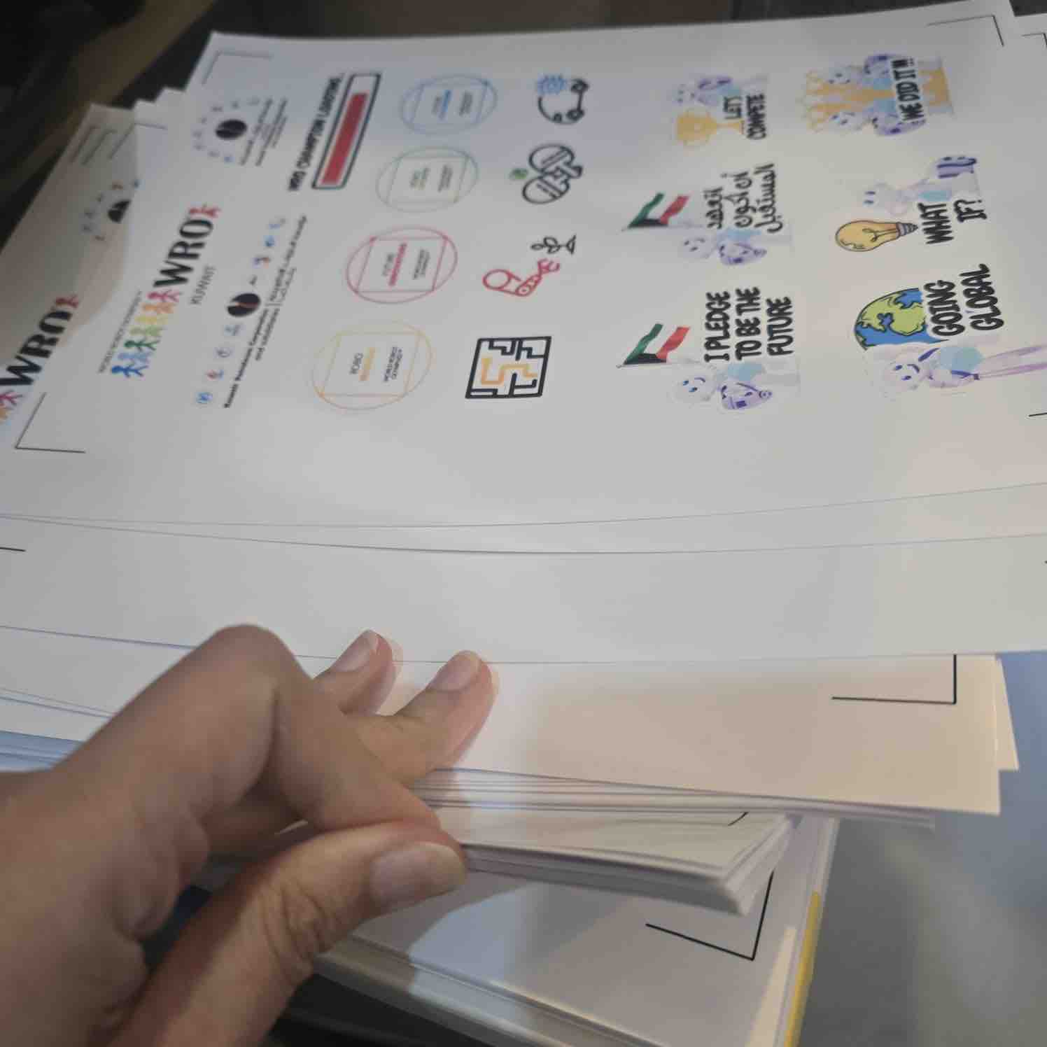
04| We have prepared hundreds of sticker sheets for season 2026 of WRO Kuwait.
05| I later reused the vinyl cutter to set up and produce vinyl-cut copper-tape PCBs — documented in Week 08 — Electronics Production and Week 10 — Output Devices, and used on the final project.
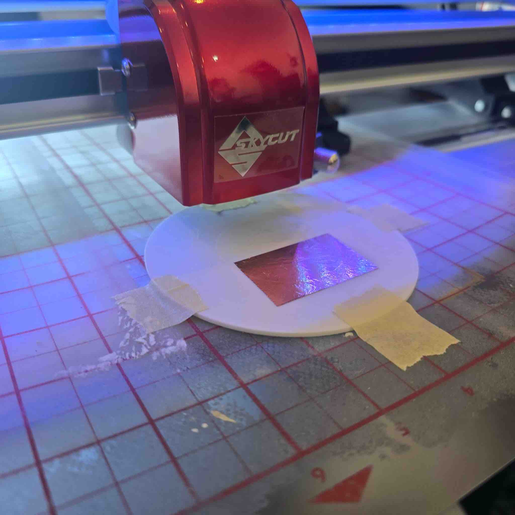
06 | Workflow for cutting a final design. Import the SVG design into the Skycut software → define the contour of the cutting area → stick the vinyl to the cutting mat with masking tape → load the mat into the Skycut machine → adjust the cutter head position → set the cutter speed and force → run a test cut first → initiate the full cut. (Picture to be added.)
07 | Weeding and applying the cut. After the machine finishes: remove the cutting mat from the machine → peel off the masking tape → weed the unwanted vinyl pieces away from the design → apply transfer tape over the cut vinyl → place the cut on the desired surface and slowly peel back the transfer tape, leaving the vinyl behind. (Picture to be added.)
- Feedback: One of the most useful tools we use, in a cost-effective process. Labor costs in Kuwait are very high. Doing it ourselves made a huge difference in the cost.
- Challenge: We still haven't found a way to feed a roll of stickers into the machine — we have to fix each sticker page on the cutting mat.
Option 02: Shoulder Pads
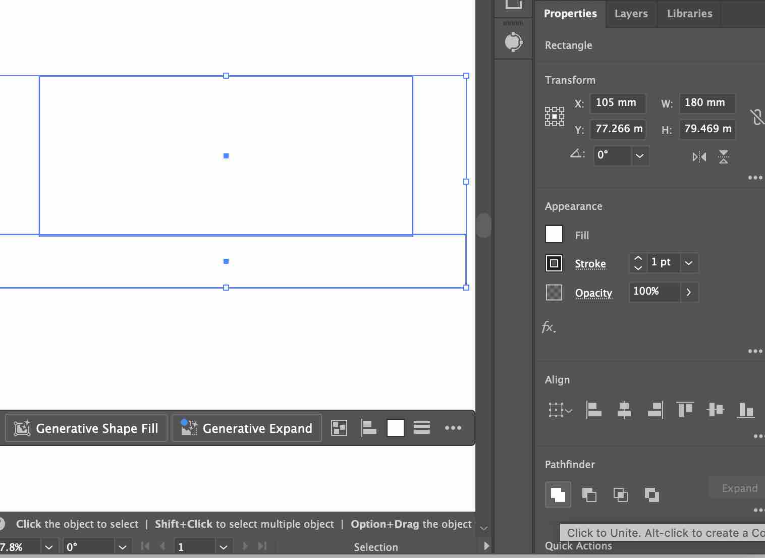
01| I used Adobe Illustrator to create the vector 2D design for the shoulder pad prototype for my final project.
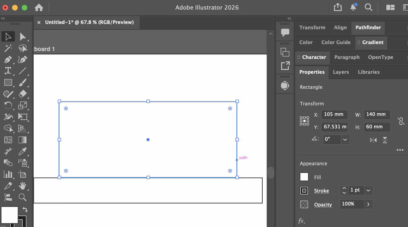
02| I defined the size in "mm" and also merged the main shapes into one
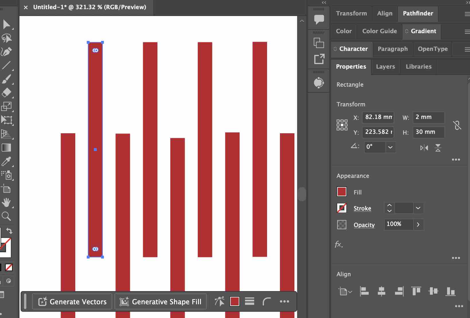
03| Then I started creating 2mm cutout shapes in this pattern to make the cardboard flexible in this area
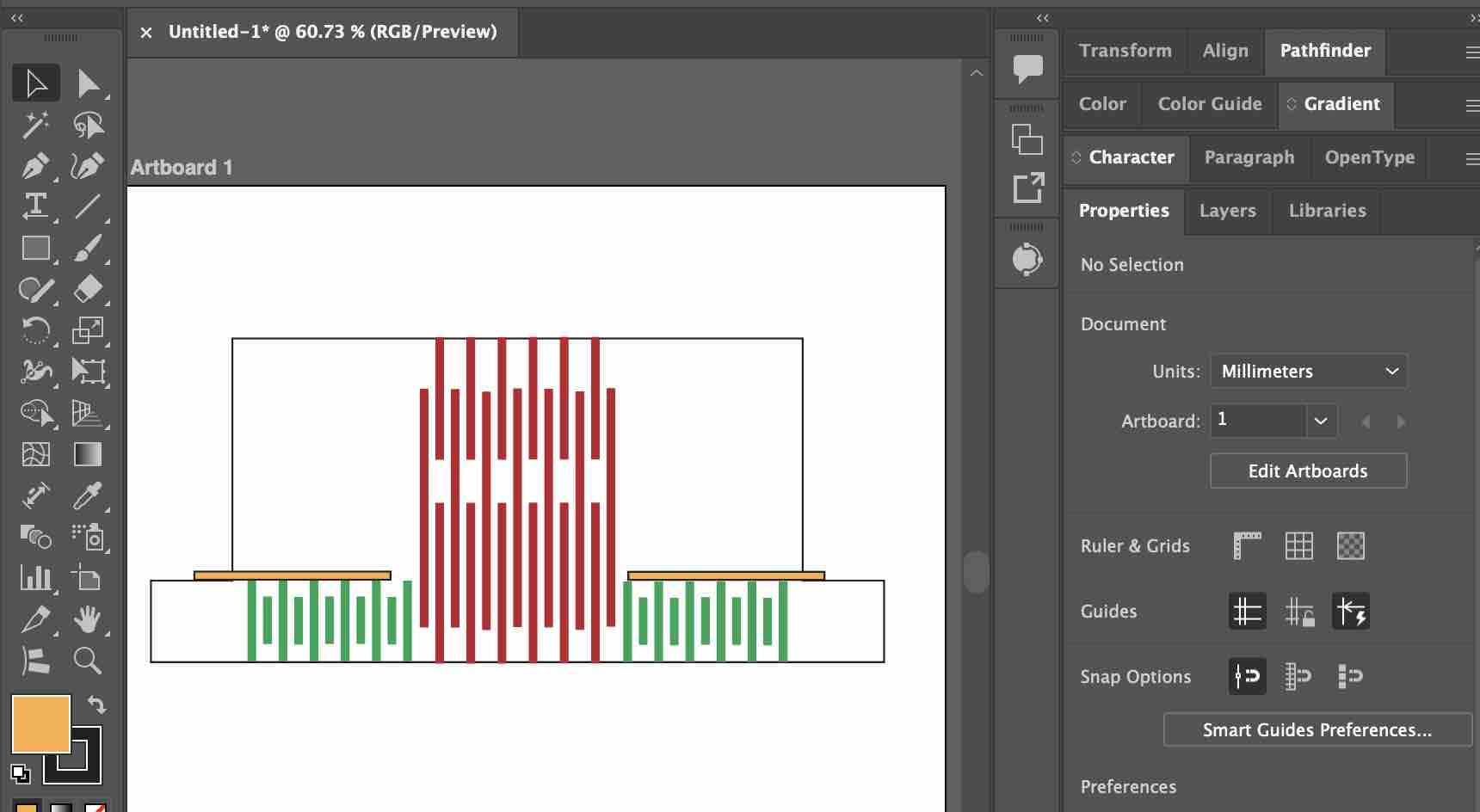
04| I repeated the same process for the strap that will go around the arm
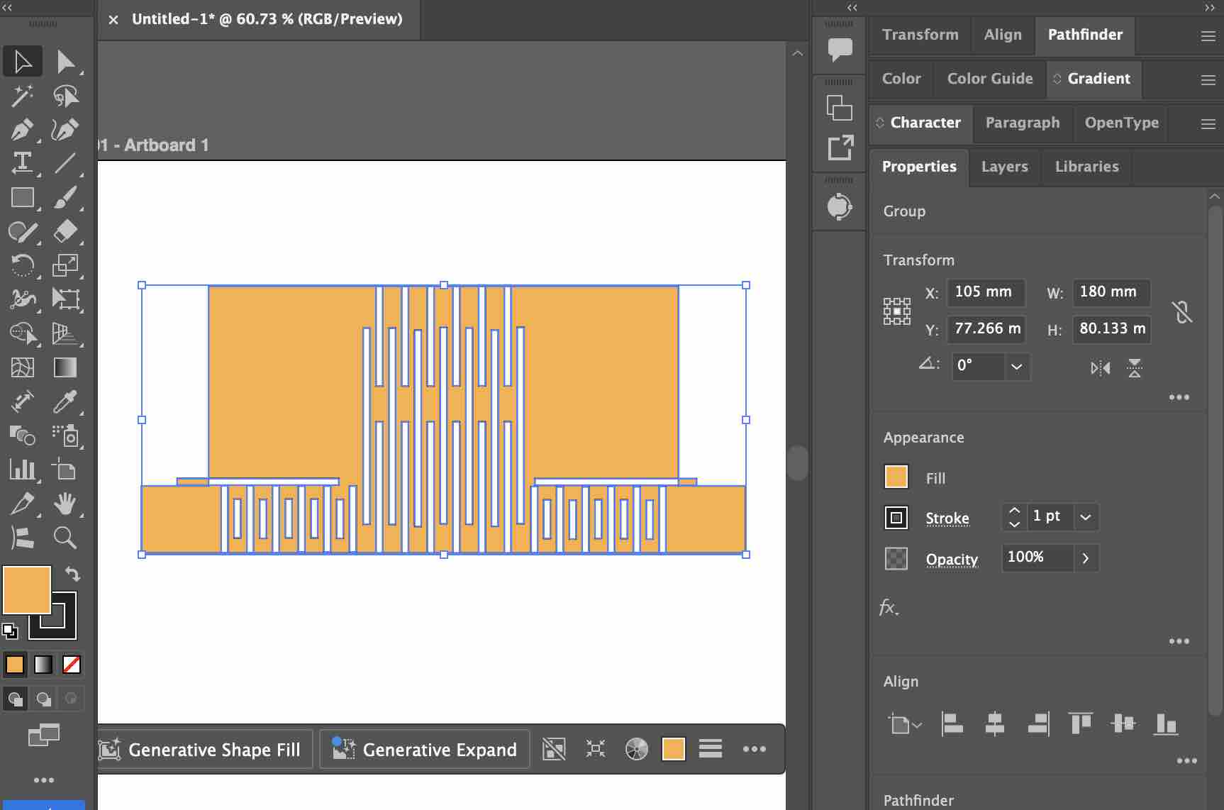
05| I selected all the shapes and created a compound shape
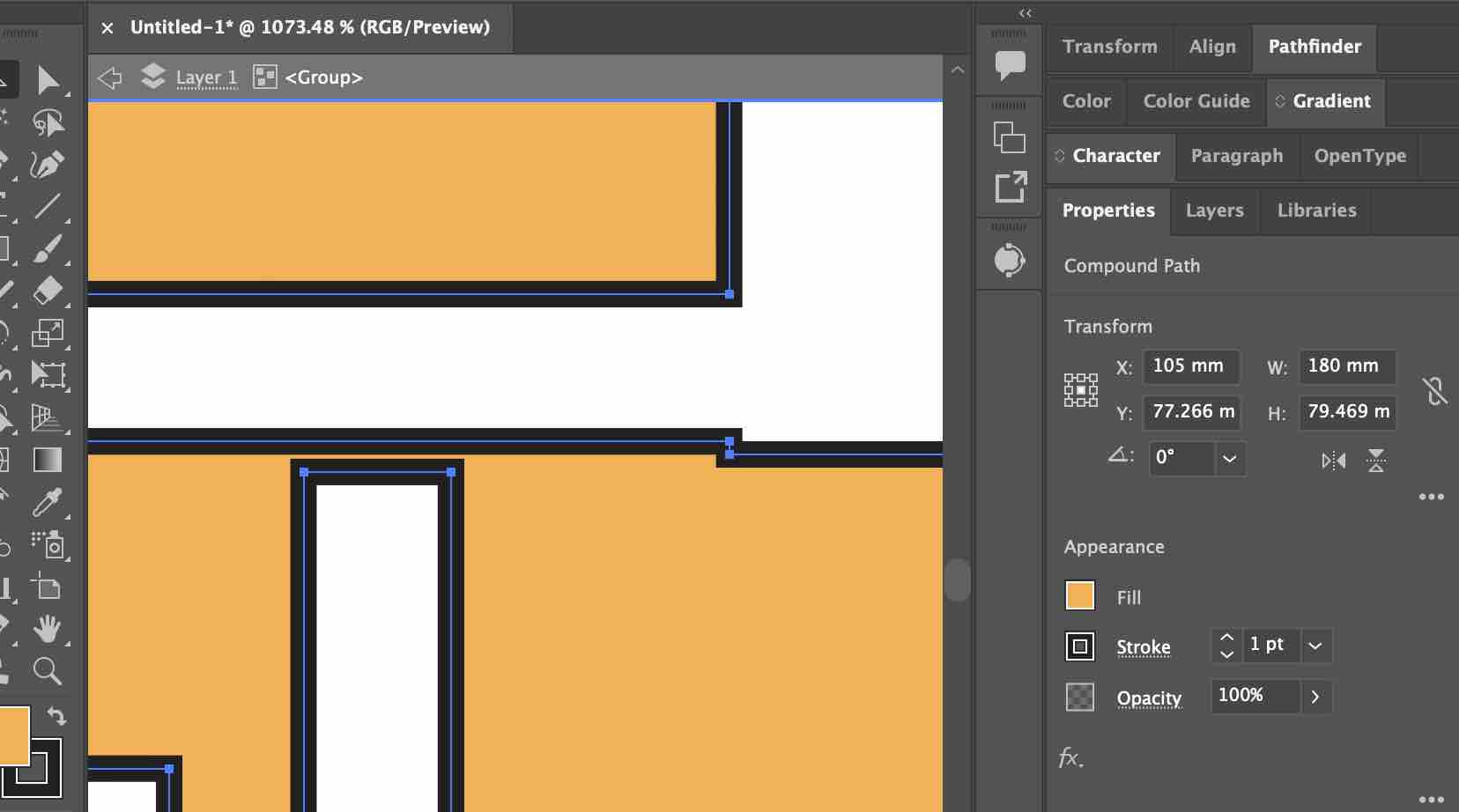
06| There were some errors and I was fixing them as I went. I noticed here that the patterns are not correct and need to be changed
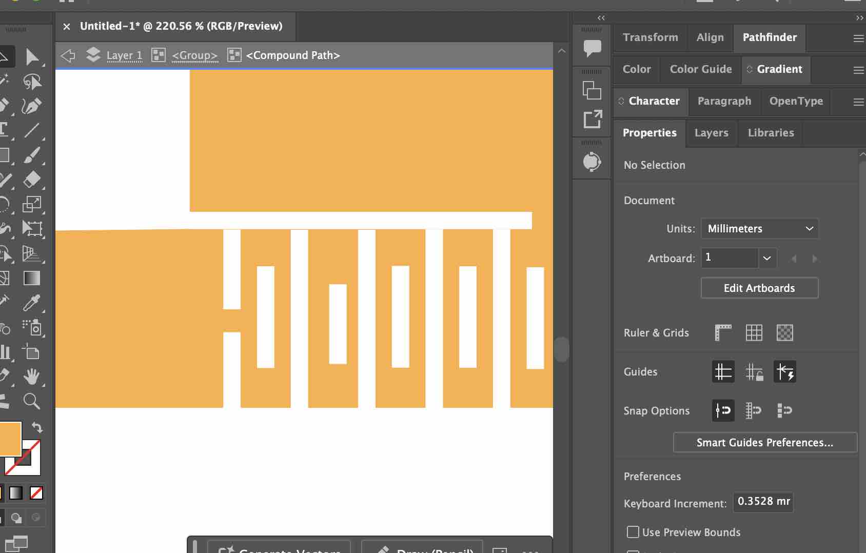
07| I noticed that the patterns created on the strap are not correct and the cardboard will be cut into pieces
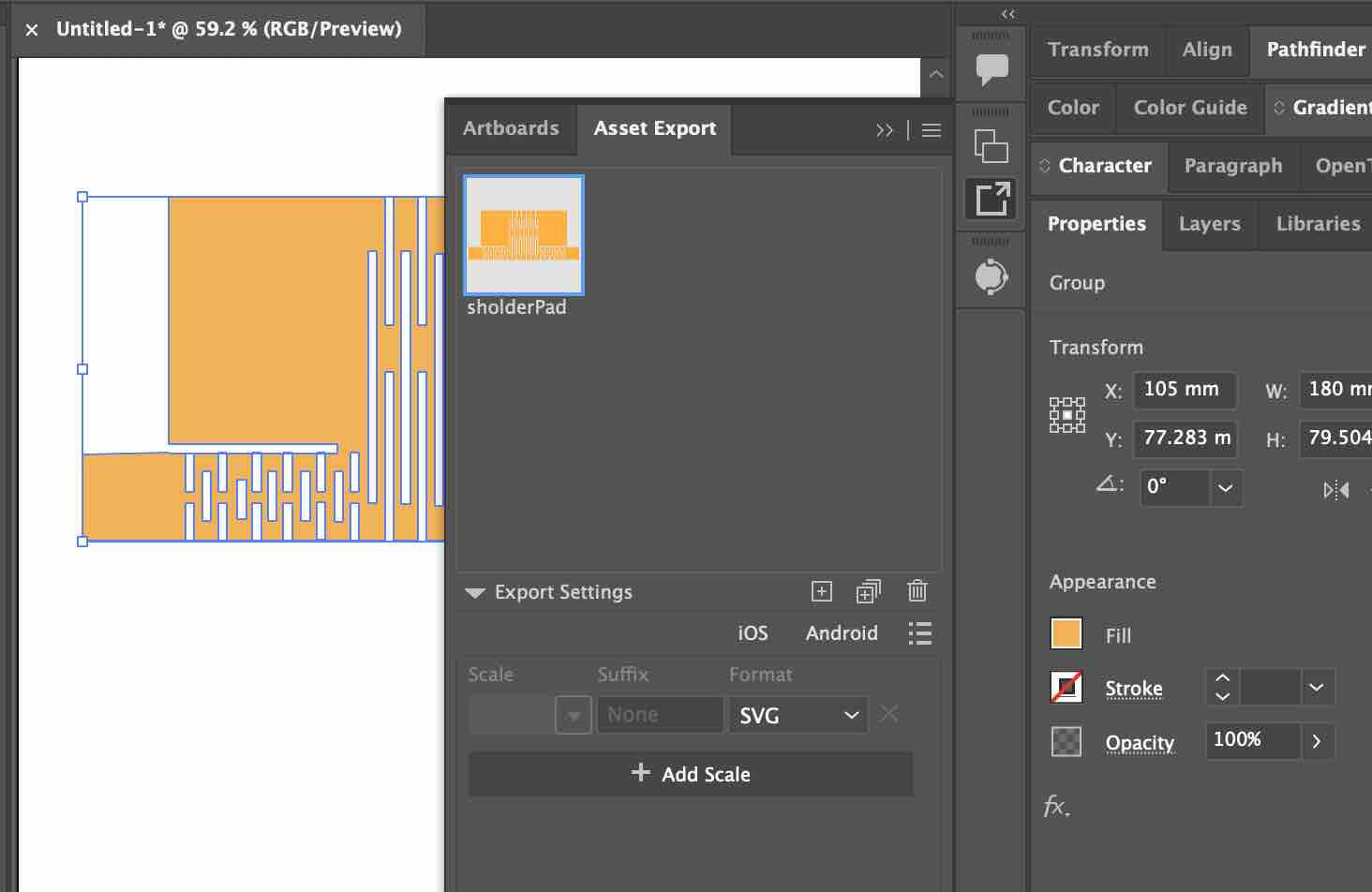
08| When I was done, I exported the design in SVG and imported it to Xtool Software
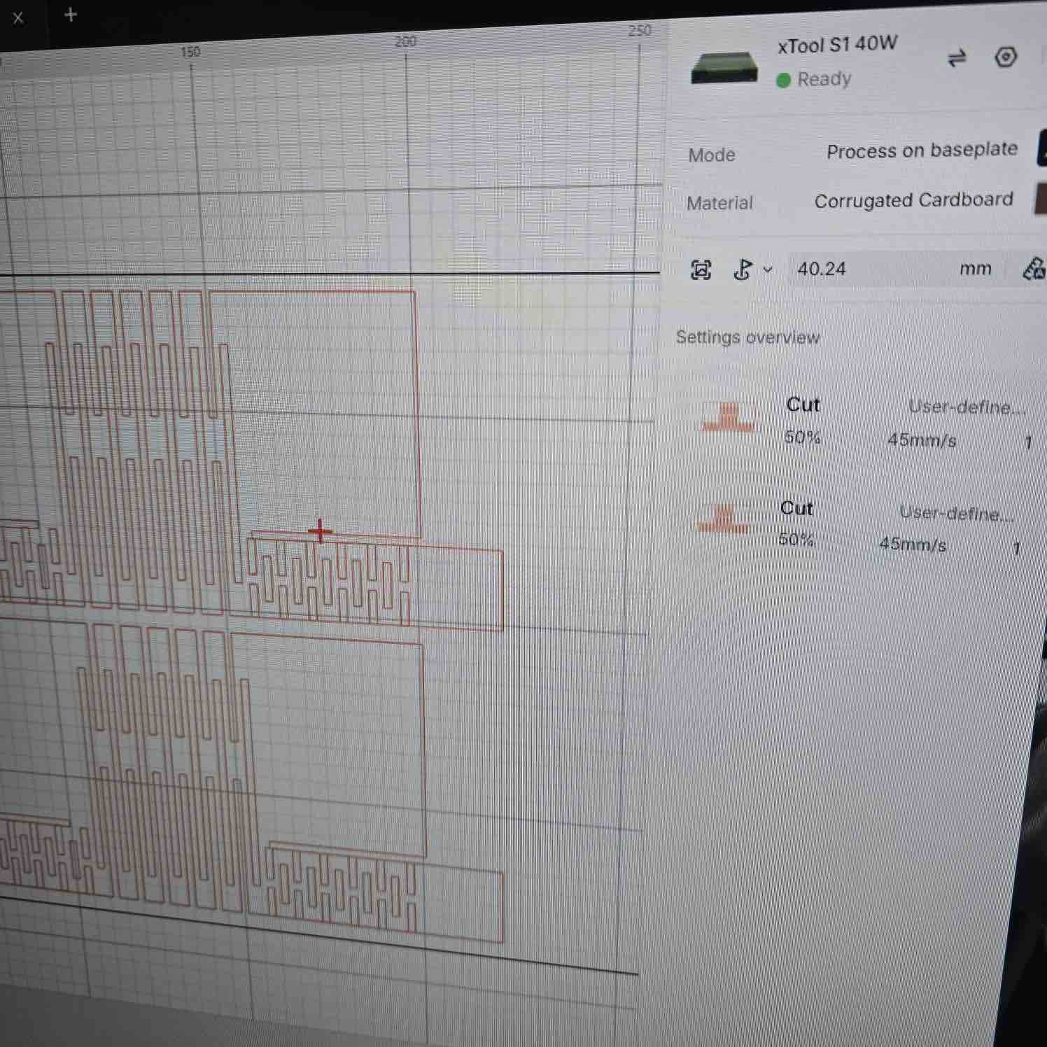
09| I imported the file to xTool Studio and set the speed to 45 and power to 50
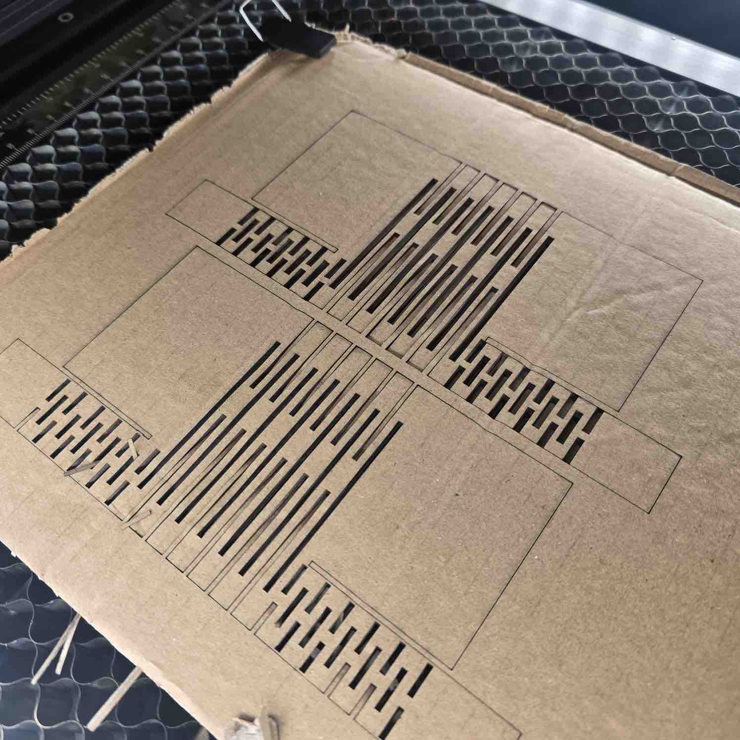
10| The cut was only on the surface and didn't go through the cardboard.
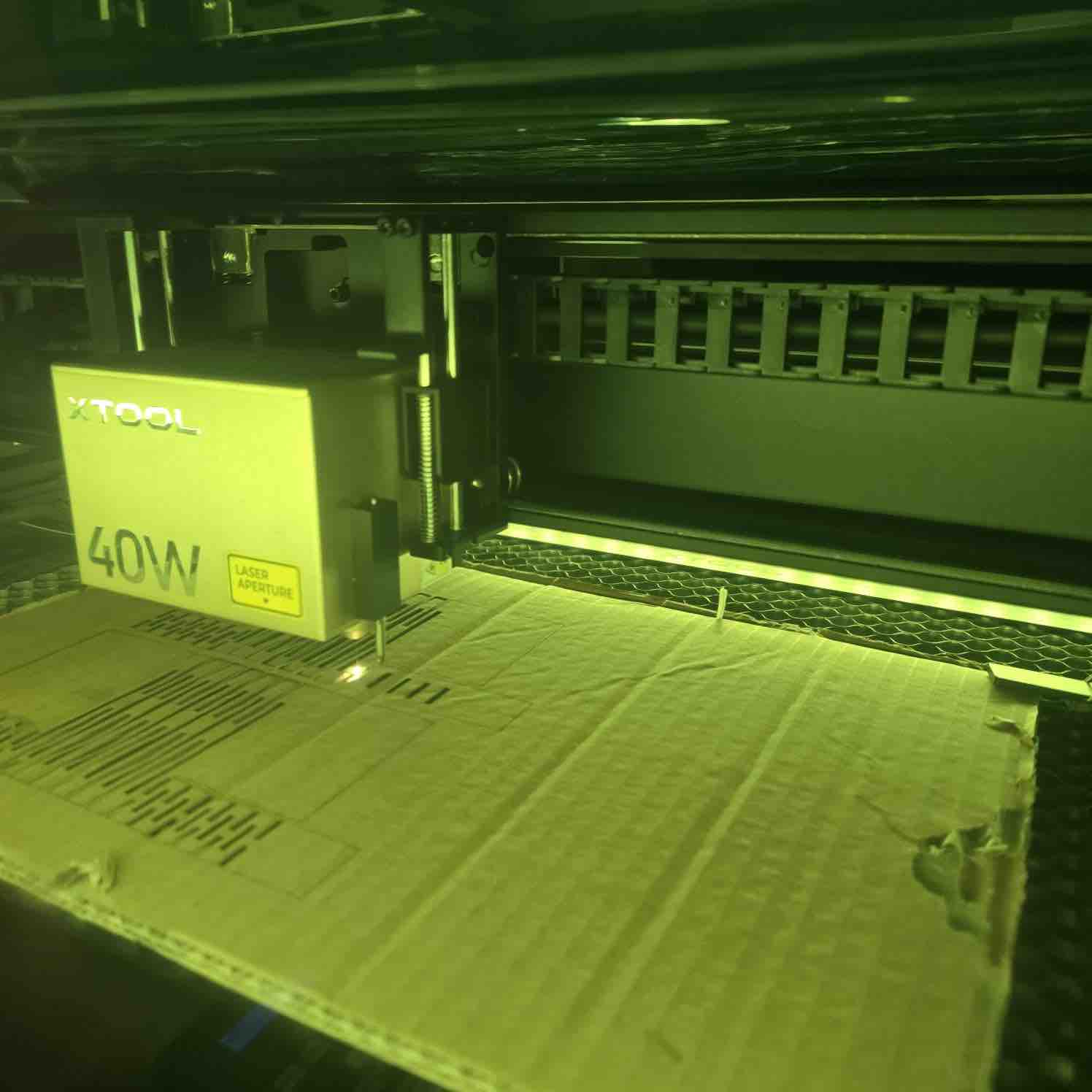
11| I adjusted to power 70 and speed 40, and the cardboard caught on fire. It was a serious situation and I couldn't take a picture in the moment.
- Feedback: Because I'm making a wearable device, I really need to make sure my design and size will fit different body sizes and shapes.
- Challenge: This prototype helped me eliminate this design, but I might use laser cutting to make the case.
Trial 03: Wooden case with living hinges
I started this trial in Week 15 but documented it here to keep the laser-cutting work together. The case is the carry case for the two clips of my final project — designed parametrically in Fusion 360 and cut on the xTool S1.
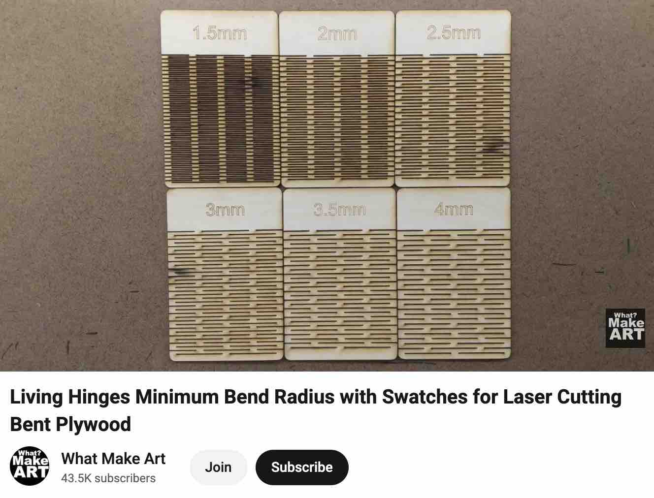
01| This video was the main reference I used to learn more about living hinges.
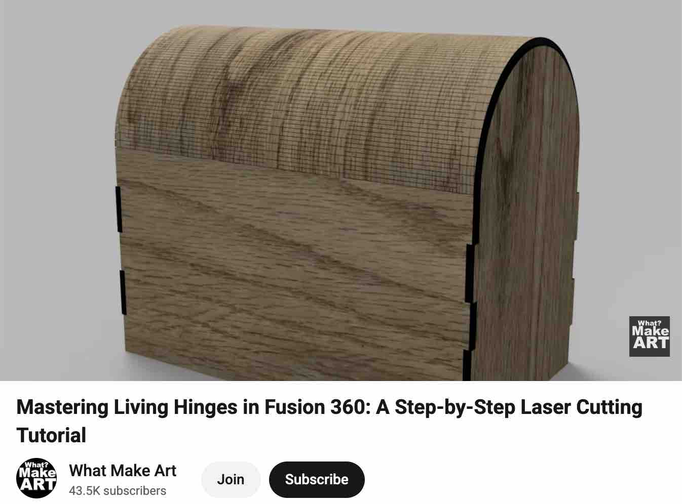
02| Plus this reference on designing the case in Fusion 360 and preparing it for export to the laser cutter.
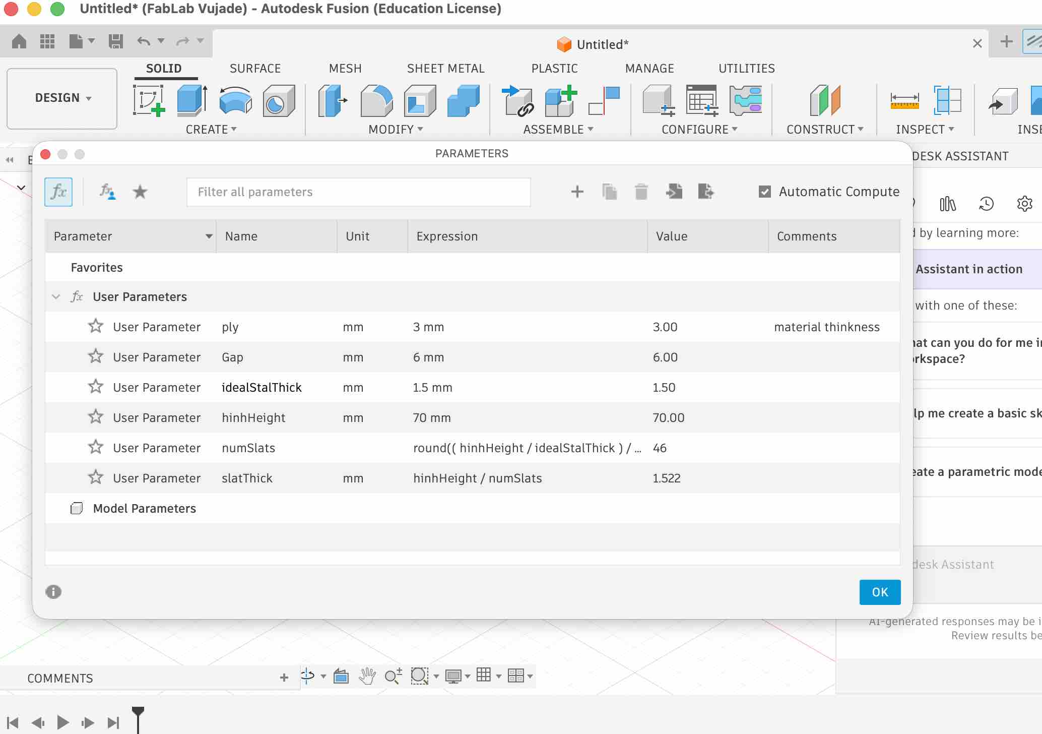
03| I set up the main parameters for the parametric design — especially important since I didn't yet have the exact dimensions of the clips I was still fabricating.
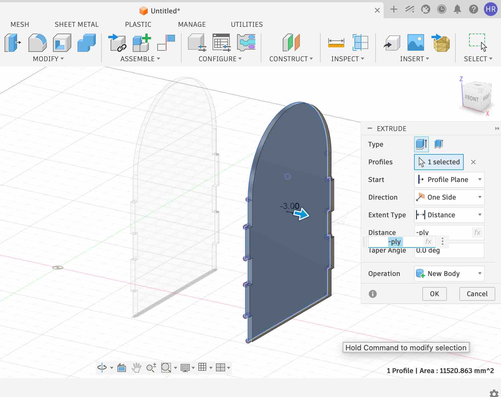
04| I created one side of the case and then mirrored it — not just to get an identical copy, but so the second side stays in relation to the first. Any change on the main side is immediately reflected on the second, removing the risk of human error from manually duplicating edits.
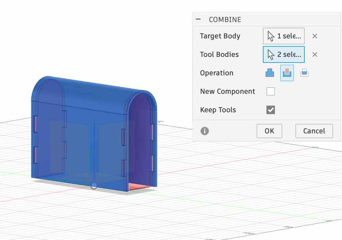
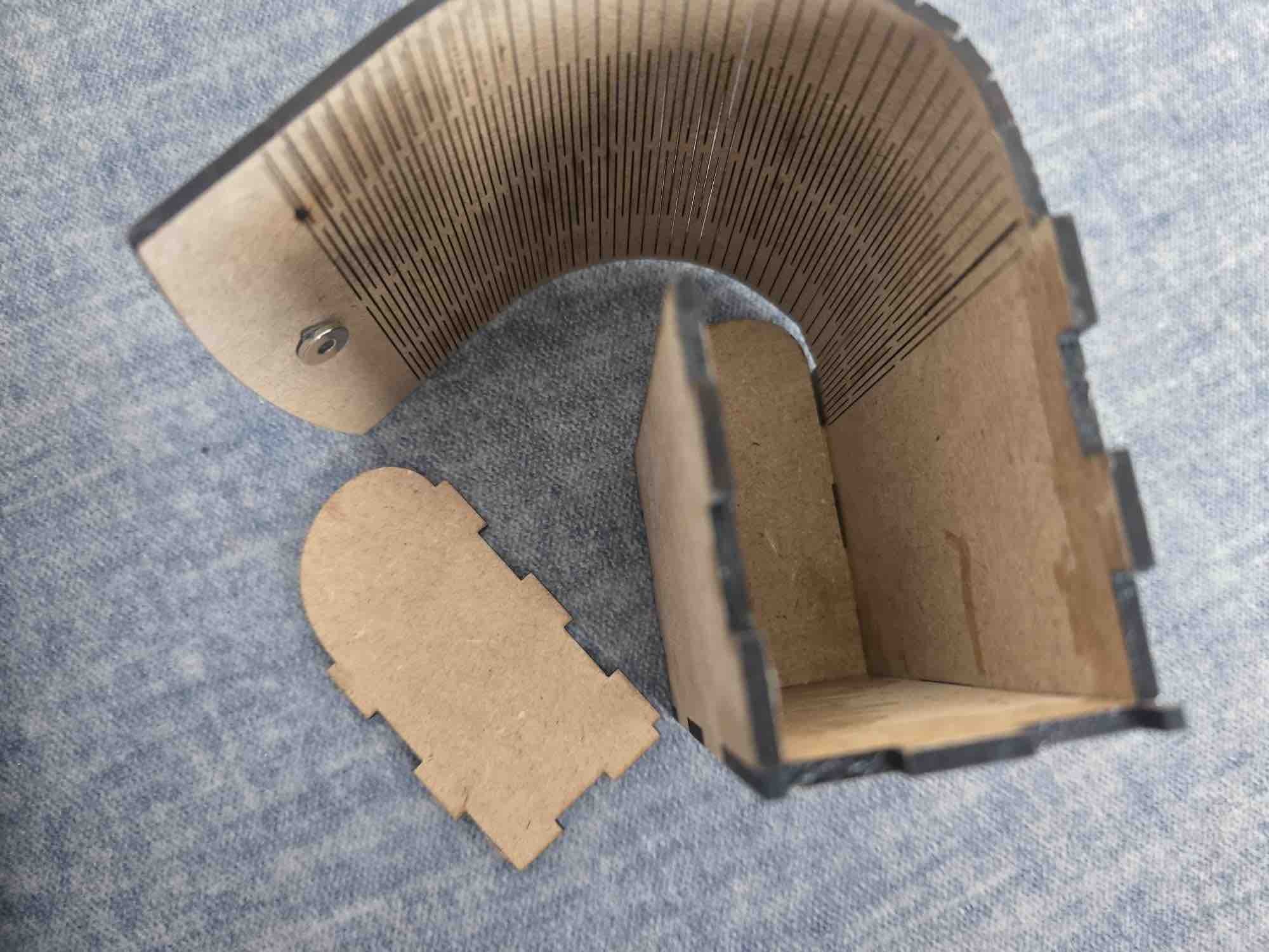
05| Creating the hinge between the sides to form the main cover of the case.
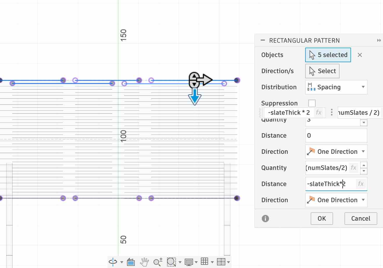
06| Aligning and designing the living hinges in detail — again using constraints and mirroring the slats so the parametric model drives all repetitions.
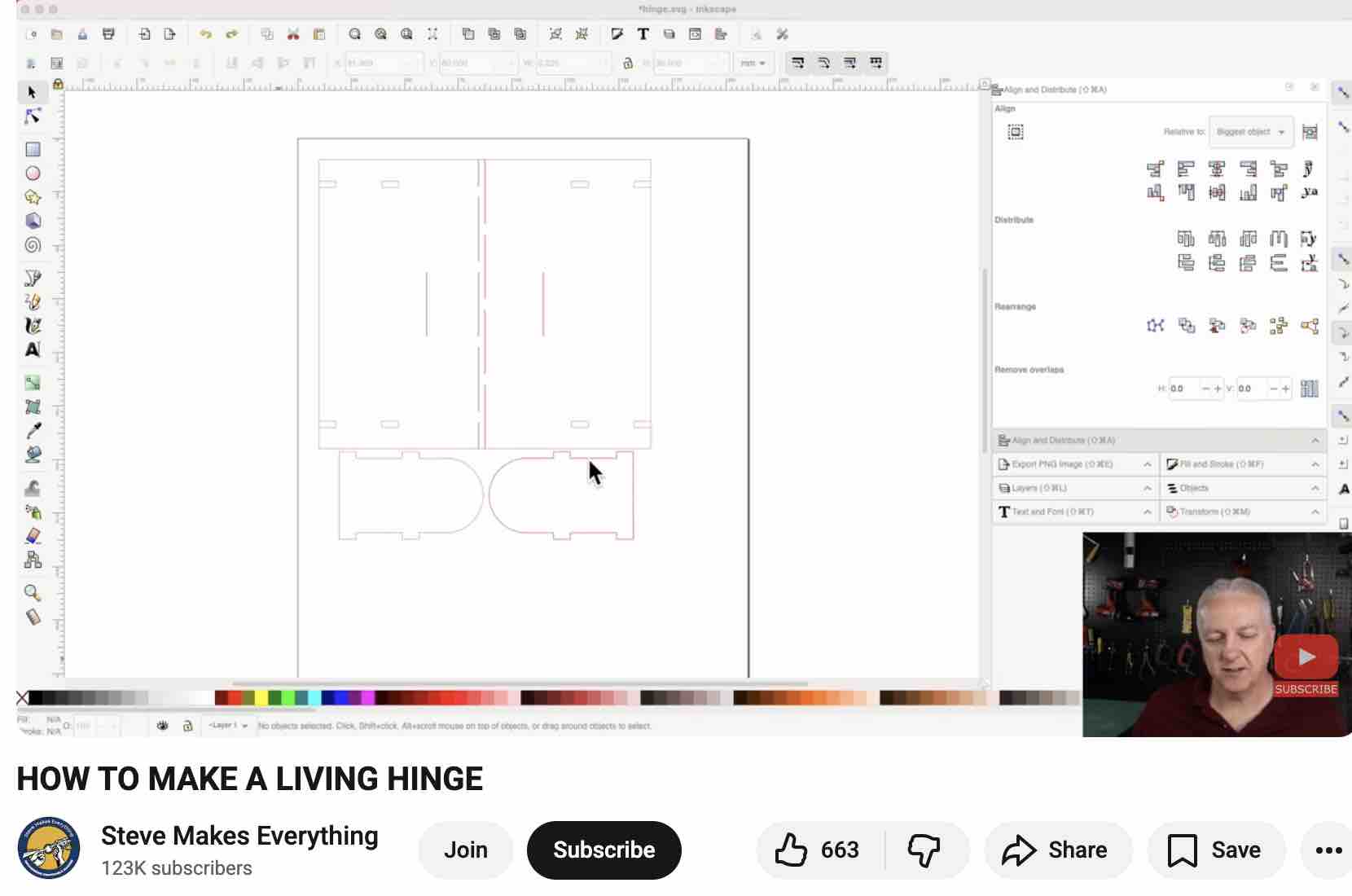
07| At this point I found some mistakes in my design — it seems I missed steps along the way. Given how much time backtracking would take, I decided to restart with a different method, following this YouTube tutorial.
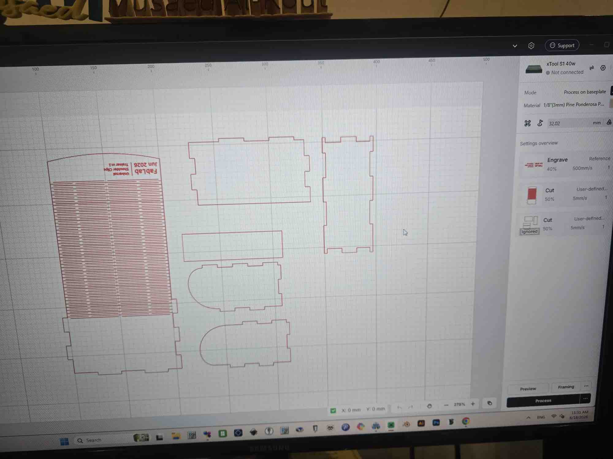
08| The final design covers all sides plus the living hinges. The case is 140 mm wide × 60 mm long × 75 mm high and this is the original file.
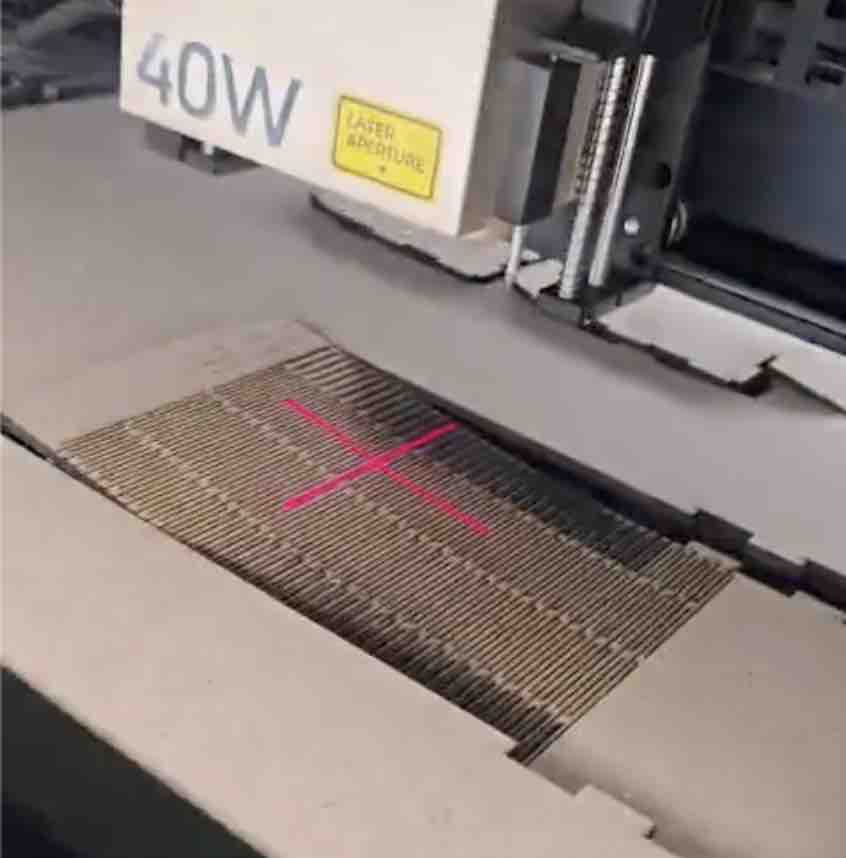
09| The text was engraved (40% power, 500 mm/s) and everything else was cut through (50% power, 5 mm/s) — the slow cut speed kept the wood from catching fire.
10| I had to use wood glue to hold the pieces together. As a spiral-development iteration, I'll look for ways to join the wooden sides without glue (press-fit / slot-and-tab) on the next revision.
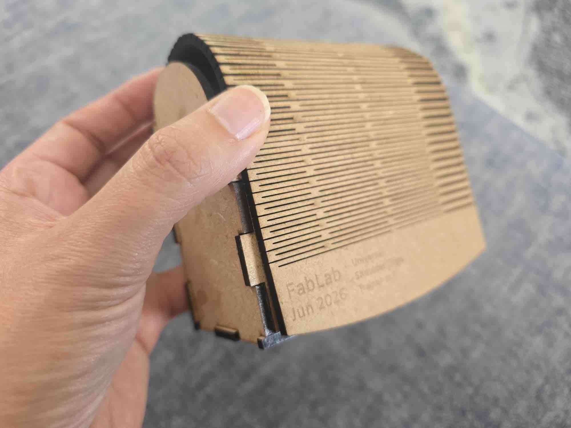
11| There's still room for improvement — particularly the top living-hinge cover — but for now, it's a job well done.
- Feedback: The reference tutorial was 17 minutes long but it took me about 2 hours, since this was my first Fusion 360 project — I had to learn the shortcuts, the commands, all of it. I still find it amazing once it clicks.
- Challenge: I'm setting a personal challenge: every Wednesday after FabLab I'll commit time to a Fusion project, and I'll also record short, to-the-point videos to help others get going without the overwhelmed feeling I had with the long tutorials — to make things easier for the next FabLab cohort and my future students.