What We Were Asked to Do
👤 Individual Assignment
- Design and document the system integration for your final project
System Integration Strategy & Plan
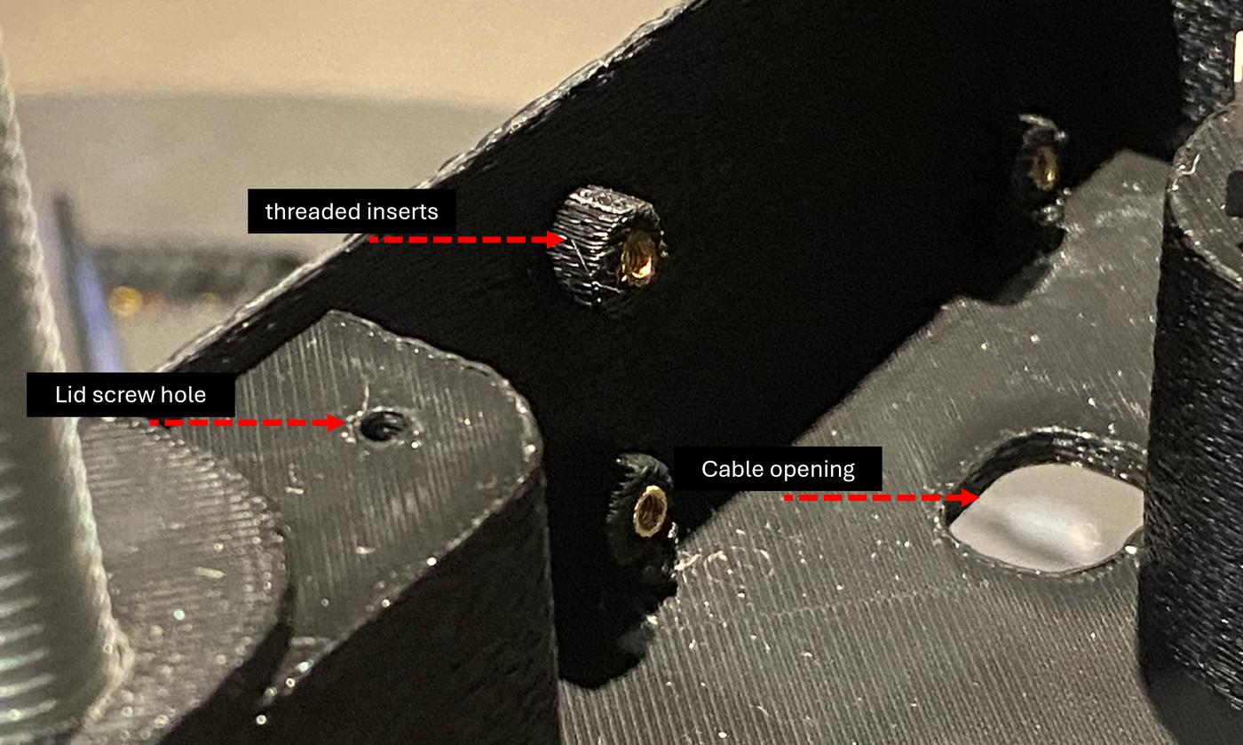
For my final project, the intent was to create a minimal, industrial, and well-integrated practical lamp. The integration strategy was to keep each module — structural, electrical, and software — independently functional before connecting them. This made troubleshooting much easier: for example, I made mounting points for the PCB and a cable opening in the enclosure, but I missed positioning them correctly in the first print. When the lamp didn't react, I knew the issue was in the firmware or wiring, not the physical enclosure. I planned the assembly order from the inside out: PCB first, then the LED strip with the enclosure body, then the diffuser cap, and finally the outer enclosure.
Assembly Order
PCB → LED strip + enclosure body → spherical diffuser cap → outer acrylic box → rod-and-nut system connects everything together
System Integration & Fabrication Methods
The Structural Module
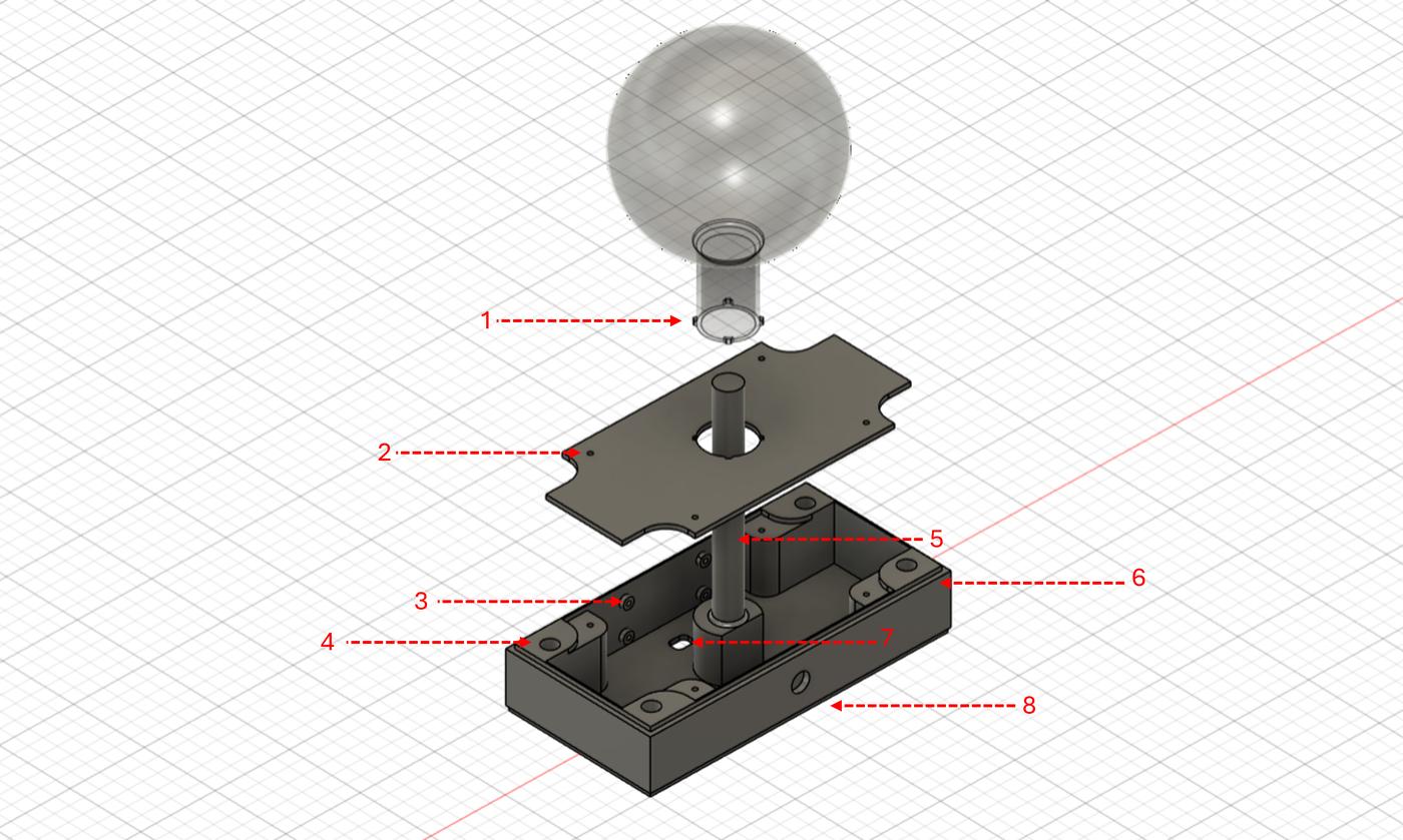
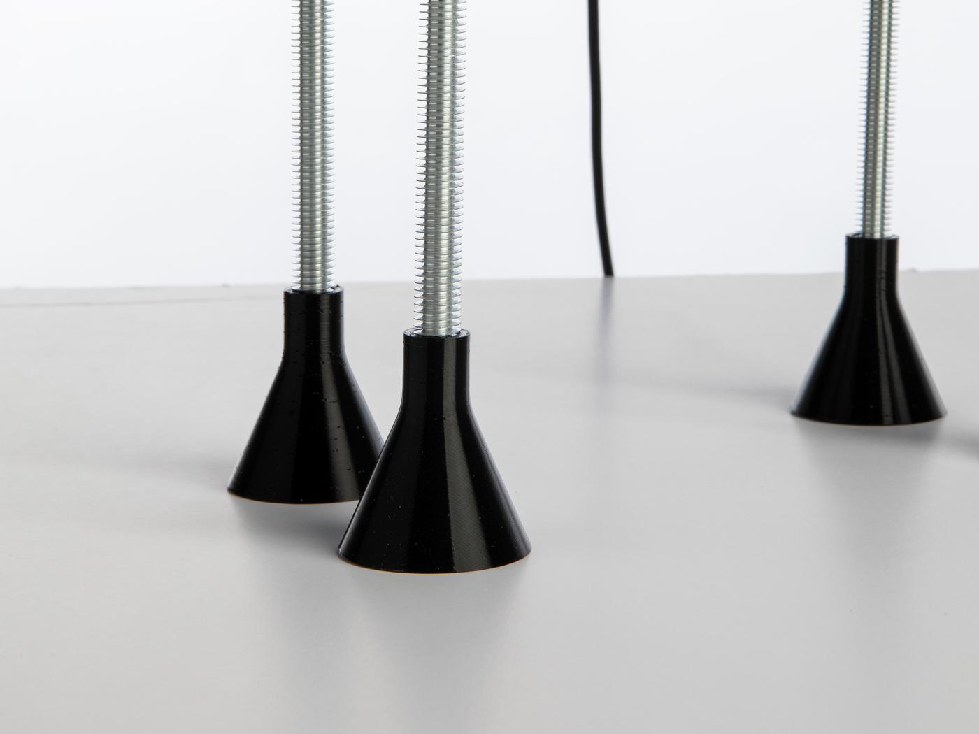
When I designed Lamperto in Fusion 360, I made sure everything was well-mounted and tidy in the most minimal way possible. The structure has three main elements: the 3D-printed parts (wiring enclosure, lid, and spherical diffuser), the upper laser-cut acrylic box, and the threaded rods that connect everything together.
3D-Printed Parts
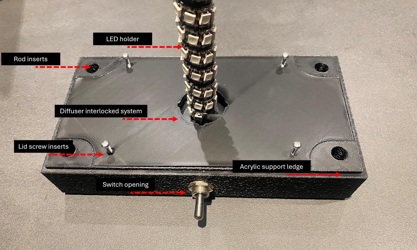
The wiring enclosure, spherical diffuser, and leg protectors were 3D printed using PLA and TPU on the Bambu Lab A1. When designing the wiring enclosure, I built in all the features needed for clean system integration:
| # | Feature |
|---|---|
| 1 | Spherical diffuser interlocking system |
| 2 | Lid with 3mm screw inserts |
| 3 | PCB mount with 3mm screw inserts |
| 4 | Leg rod inserts to connect the enclosure with the upper box |
| 5 | LED strip mount |
| 6 | Support ledge to hold the acrylic box in place |
| 7 | Cable opening |
| 8 | Switch opening |
Bambu Lab A1
PLA (white & black) + TPU (black)
Fusion 360
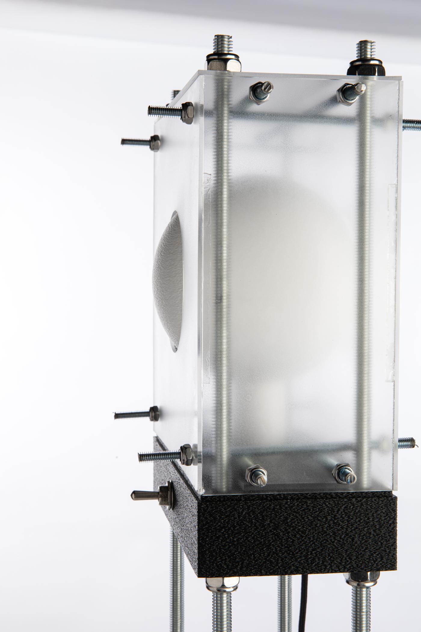
Laser-Cut Acrylic Upper Box & Rod-and-Nut System
I laser cut the upper enclosure from 2mm acrylic sheet. The rod-and-nut system — using 6mm and 10mm diameter threaded steel rods — connects the upper acrylic box to the wiring enclosure and acts as the lamp's structural spine. This system worked exactly as designed and made the lamp easy to open for iteration: no glue, no permanent fixings, and the whole thing disassembles in minutes.
The Electrical Module
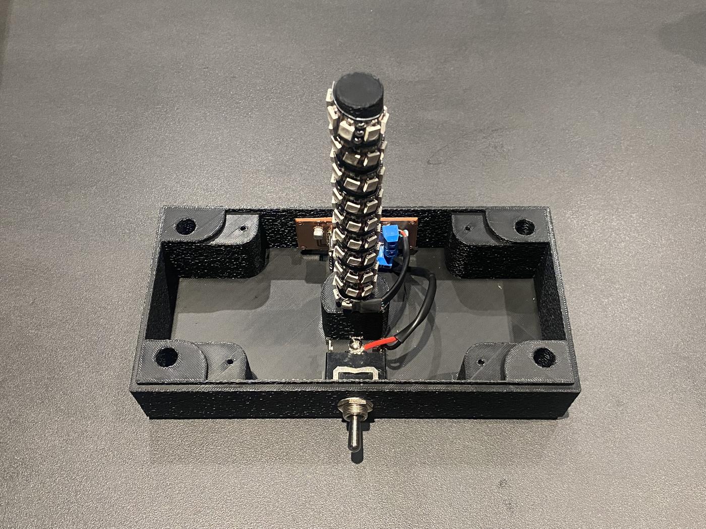
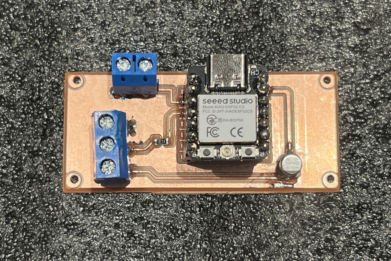
The brain of Lamperto is a custom PCB I designed in KiCad and milled at the lab. The board is built around the XIAO ESP32-C3 and handles the toggled switch and the 5V WS2812B strip of 67 LEDs. A 330Ω resistor protects the data signal line, and a 1000µF decoupling capacitor stabilises the power rail. I positioned everything on the board to align with the wiring enclosure design so the PCB mounts directly onto the printed screw inserts for a clean, secure fit. The device is powered by an external power supply with an adaptor to protect the electronics.
PCB Design & Fabrication
The PCB was designed in KiCad (schematic + layout), milled on the CNC milling machine at the lab, and assembled by hand using SMD and screw-terminal components for a clean finish. I added mounting holes to secure the board directly to the enclosure. After soldering, I ran continuity checks on every net before powering up.
⬇ Download KiCad Files ZIP · 35 KB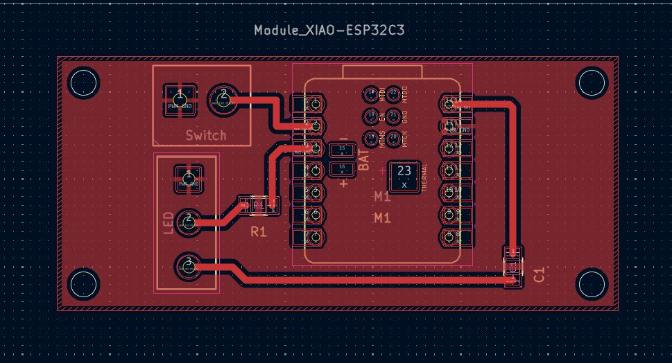
Embedded Programming & Wireless Integration
Embedded Programming
The firmware runs on the XIAO ESP32-C3 using Arduino IDE. It controls the WS2812B LEDs via an addressable strip library and reads Blynk virtual pins to receive schedule and brightness data from the app.
Wireless & App Integration
The ESP32-C3 connects to Wi-Fi and syncs with the Blynk IoT platform. I built a custom Blynk dashboard that allows scheduling and manual brightness control from a phone — so Lamperto knows when to turn on, when to dim, and what intensity to hold throughout the day.
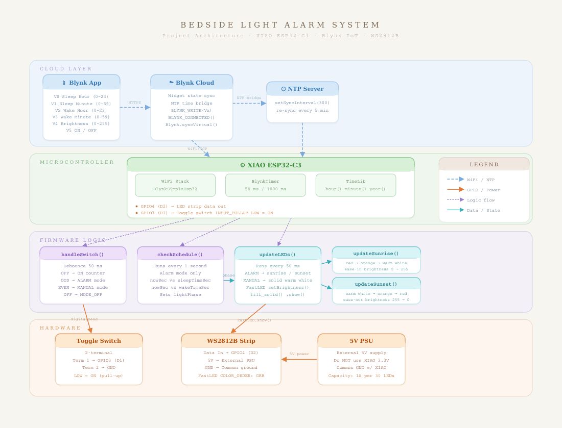
System Architecture
The diagram below shows how all modules communicate and connect. The XIAO ESP32-C3 sits at the centre, receiving input from the toggle switch and Blynk (over Wi-Fi), and driving the WS2812B LED strip as its primary output. Power flows from the external supply through the PCB to both the microcontroller and the LED strip.
Full Project BoM
| Item | Description | Qty | Unit Price | Source |
|---|---|---|---|---|
| Acrylic enclosure | 2mm acrylic sheet for laser-cut panels | 1 | $5.00 | alrish.sa |
| Locking nuts | (16) 6mm nuts + (8) 10mm nuts for rod frame | 1 pack | $3.00 | Amazon.sa |
| Threaded rods | 6mm & 10mm diameter steel rods | 1 set | $10.00 | Local hardware |
| PLA filament | White & black PLA for enclosure, diffuser, frame mount | 2 spools | $15.00 | Amazon.sa |
| TPU filament | Black TPU for flexible leg protectors | 1 spool | $1.00 | Amazon.sa |
| Toggle switch | Heavy-duty electrical toggle switch (mode selector) | 1 | $1.80 | Amazon.sa |
| Type-C cable | USB-C power cable for the ESP32 microcontroller | 1 | $9.30 | Amazon.sa |
| Screw terminals | 2-pin screw terminals (LED strip & toggle switch connections) | 2 | $0.50 | Amazon.sa |
| XIAO ESP32-C3 | Seeed Studio XIAO ESP32-C3 — Wi-Fi microcontroller | 1 | $14.00 | Amazon.sa |
| WS2812B LED strip | Addressable RGB LED strip — main light output | 1 | $5.00 | Amazon.sa |
| SMD resistor | 330Ω — LED data signal protection | 1 | $0.20 | Amazon.sa |
| SMD capacitor | 1000µF, 10V electrolytic — power rail decoupling | 1 | $0.20 | Amazon.sa |
| Total Project Cost | $65.00 | |||
Challenges & Learnings
The biggest lesson from this week was how much upfront coordination between the mechanical and electrical design matters. I missed the PCB mount positioning in my first print and had to reprint the enclosure — a mistake that would have been easy to avoid by cross-checking the PCB layout against the enclosure model before slicing. I now import both into the same Fusion 360 assembly to verify clearances first.
The rod-and-nut structural system worked exactly as intended and made the whole lamp quick to open and re-close during iteration. Not having to glue or permanently fix anything meant I could swap components, re-route wires, and test changes without any destructive steps.
Getting to the point where the Blynk app controls Lamperto's schedule and brightness wirelessly felt like the whole semester clicking into place — every week fed directly into this final integration.