Assignment Tasks
🔬 Group Assignment
- Compare as many interface/application tool options as possible
- Document findings on the group work page
- Reflect individually on what you learned
👤 Individual Assignment
- Write an application for the embedded board you made
- Interface a user with an input and/or output device
What is Blynk?
Blynk is a cloud-based IoT platform that lets makers, students, and engineers build mobile and web applications for controlling and monitoring hardware — without writing complex server or networking code.
What Blynk lets you do
- Connect microcontrollers (ESP32, Arduino, Raspberry Pi) to the internet over Wi-Fi or cellular
- Build a custom web dashboard or mobile app to control outputs and read sensor data in real time
- Use virtual and digital pins to bridge firmware with the cloud
- Visualise data, set automations, and monitor devices remotely from anywhere
Blynk is widely used in educational and prototyping contexts because it offers a free tier, an intuitive drag-and-drop UI builder, and well-documented Arduino libraries. For this week's project I used Blynk to build a web dashboard and mobile app that toggles an LED connected to a Seeed XIAO ESP32-C3 over Wi-Fi.
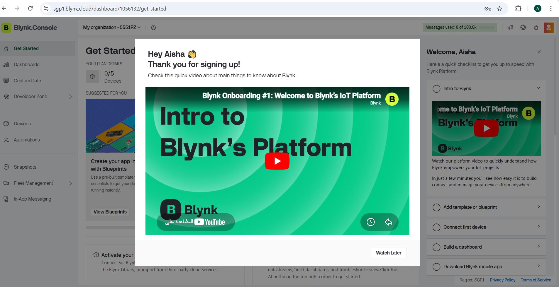
The Blynk Console at blynk.io is where you create and manage all templates, devices, and dashboards.
Step-by-Step: Setting Up Blynk
Opening the Blynk Console
Navigate to blynk.io and log in or create a free account. The Blynk Console is the main web interface where you configure templates, datastreams, and dashboards before deploying your project.
Once logged in you land on the main console, where you manage all your connected devices and projects. The next step is creating a Template that describes your hardware and its behaviour.
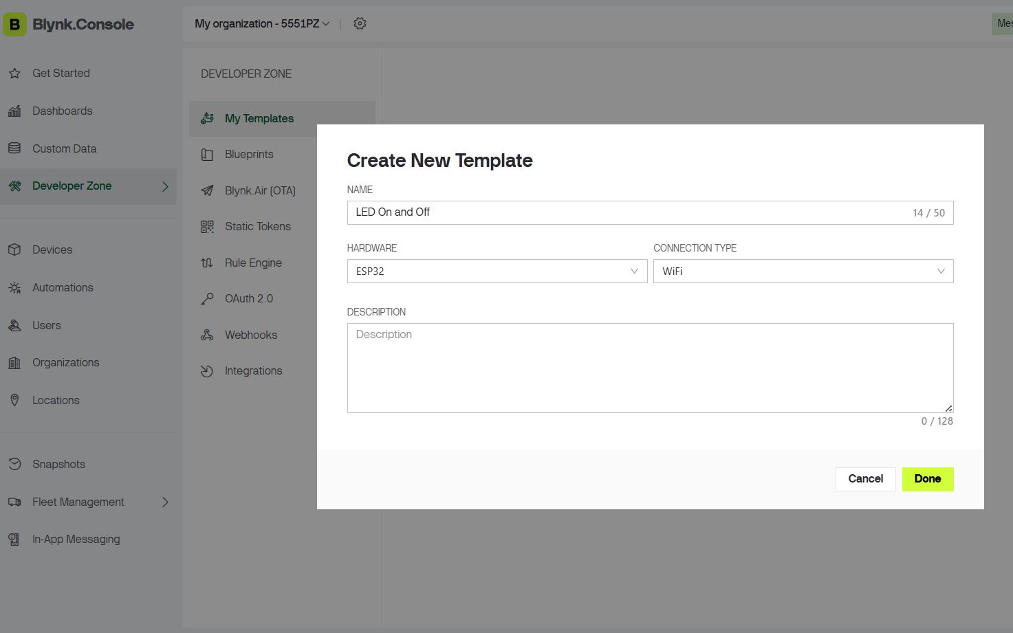
Creating a New Template
A Template is the blueprint for a device type. It defines the hardware model, connection method, datastreams, and dashboard layout. Every physical device is then registered against a template.
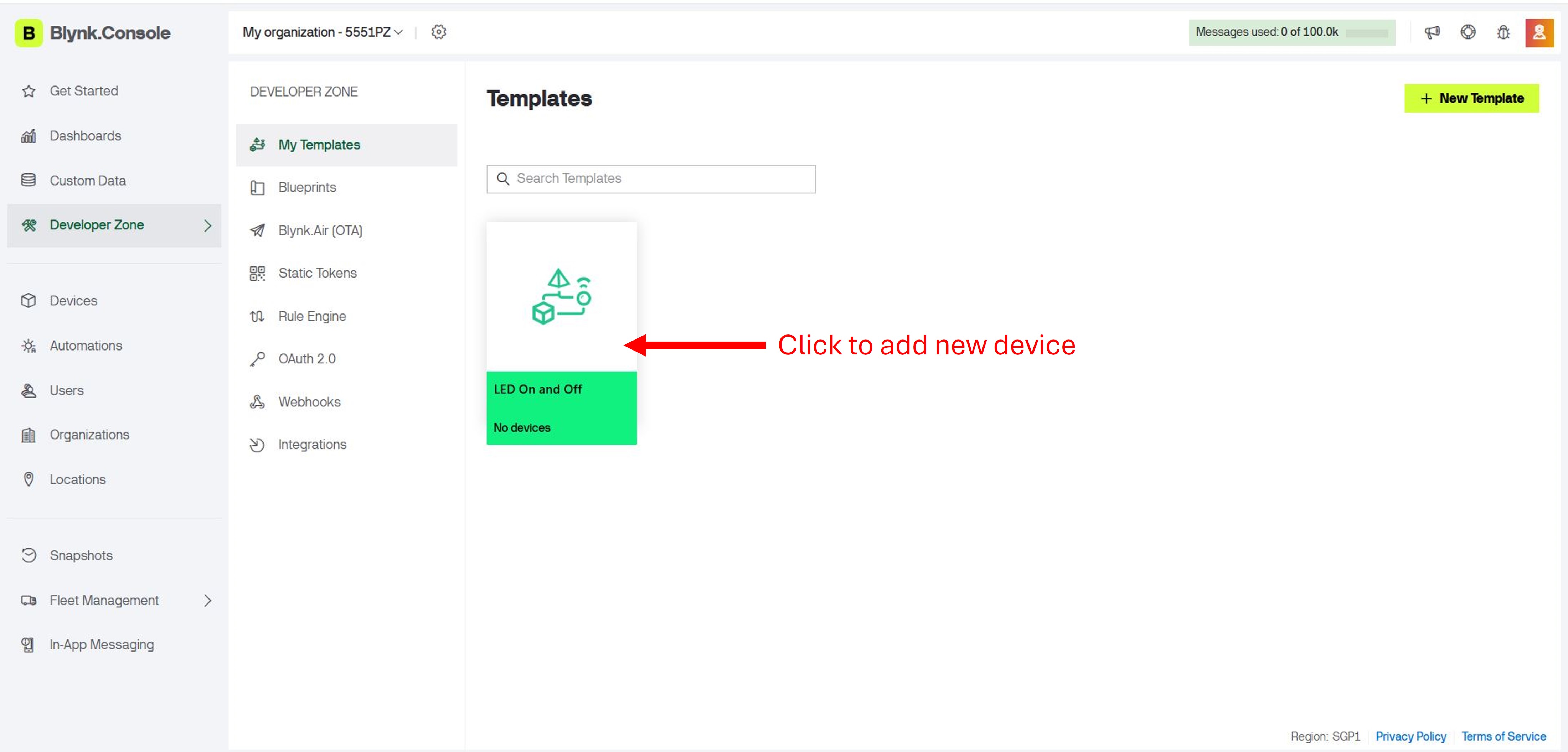
- In the left sidebar, click Developer Zone.
- Select Templates, then click + New Template.
- Fill in: Name (e.g. "LED On and Off"), Hardware (ESP32), Connection Type (WiFi).
- Click Done to save.
Choose the correct hardware and connection type — mismatched settings will prevent the device from connecting.
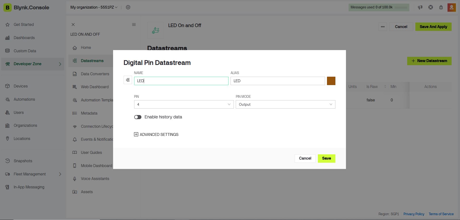
Setting Up a Datastream (Digital Pin)
A Datastream is the data channel between your hardware and the Blynk cloud. For an LED, you create a Digital Pin datastream that maps to a GPIO pin on your microcontroller.
- Inside your template, click the Datastreams tab.
- Click + New Datastream and select Digital Pin.
- Set the Name (e.g. "LED Pin 4") and Pin (D4 / GPIO 4).
- Leave Data Type as Integer (0 = OFF, 1 = ON), then click Create.
The pin number here must match the physical GPIO pin your LED is wired to on the ESP32.
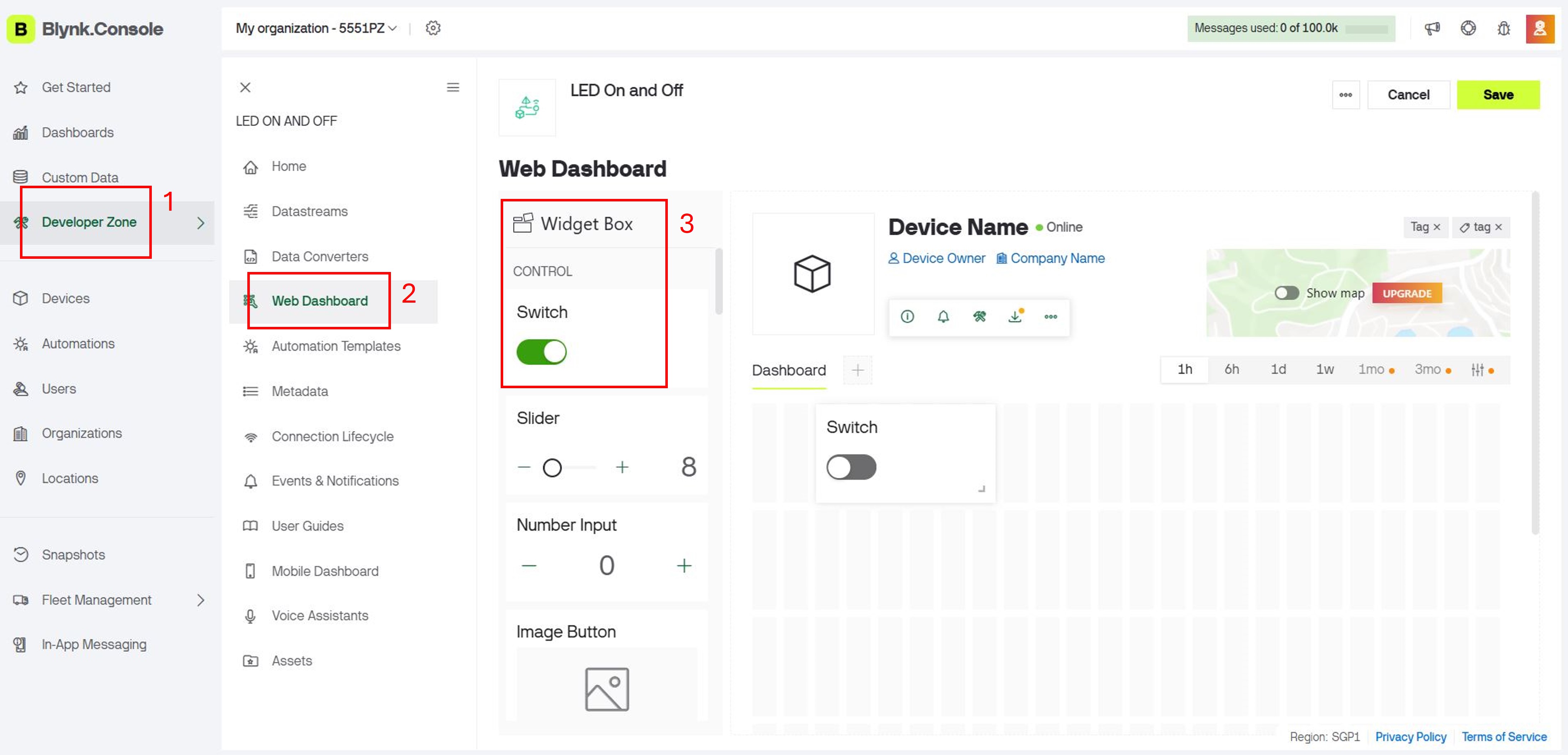
Building the Web Dashboard
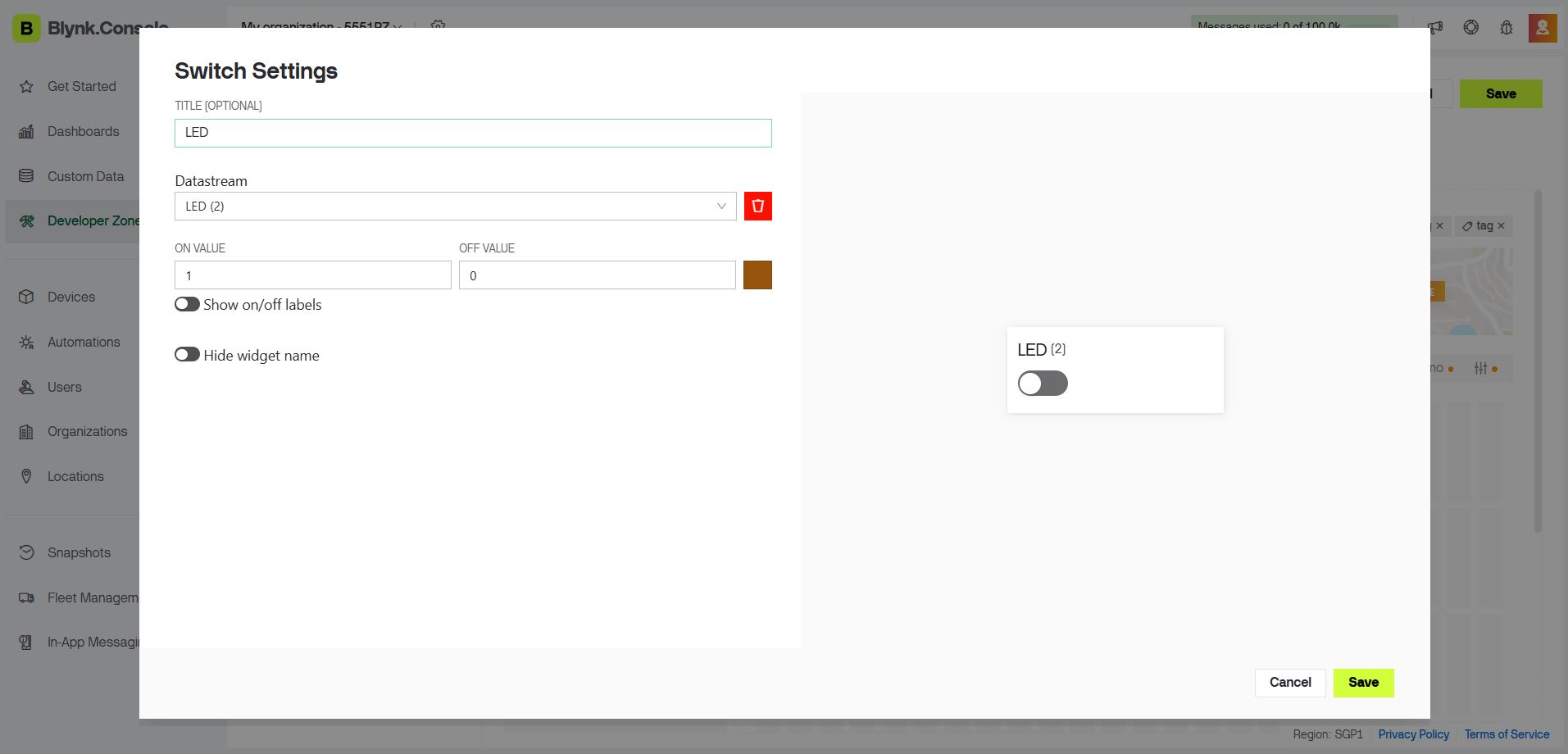
The Web Dashboard provides a browser-based interface to interact with your device. You add a Switch widget to toggle the LED on and off with a single click.
- Click the Web Dashboard tab within your template.
- In the widget panel on the right, locate the Switch widget.
- Drag the Switch onto the dashboard canvas and position it.
- Click the widget to open its settings — set the Title to "LED" and the Datastream to "LED Pin 4".
- Click Save.
You can resize widgets by dragging their edges. Plan your layout before adding multiple widgets to keep the dashboard clean.
Saving the Template & Adding a Device
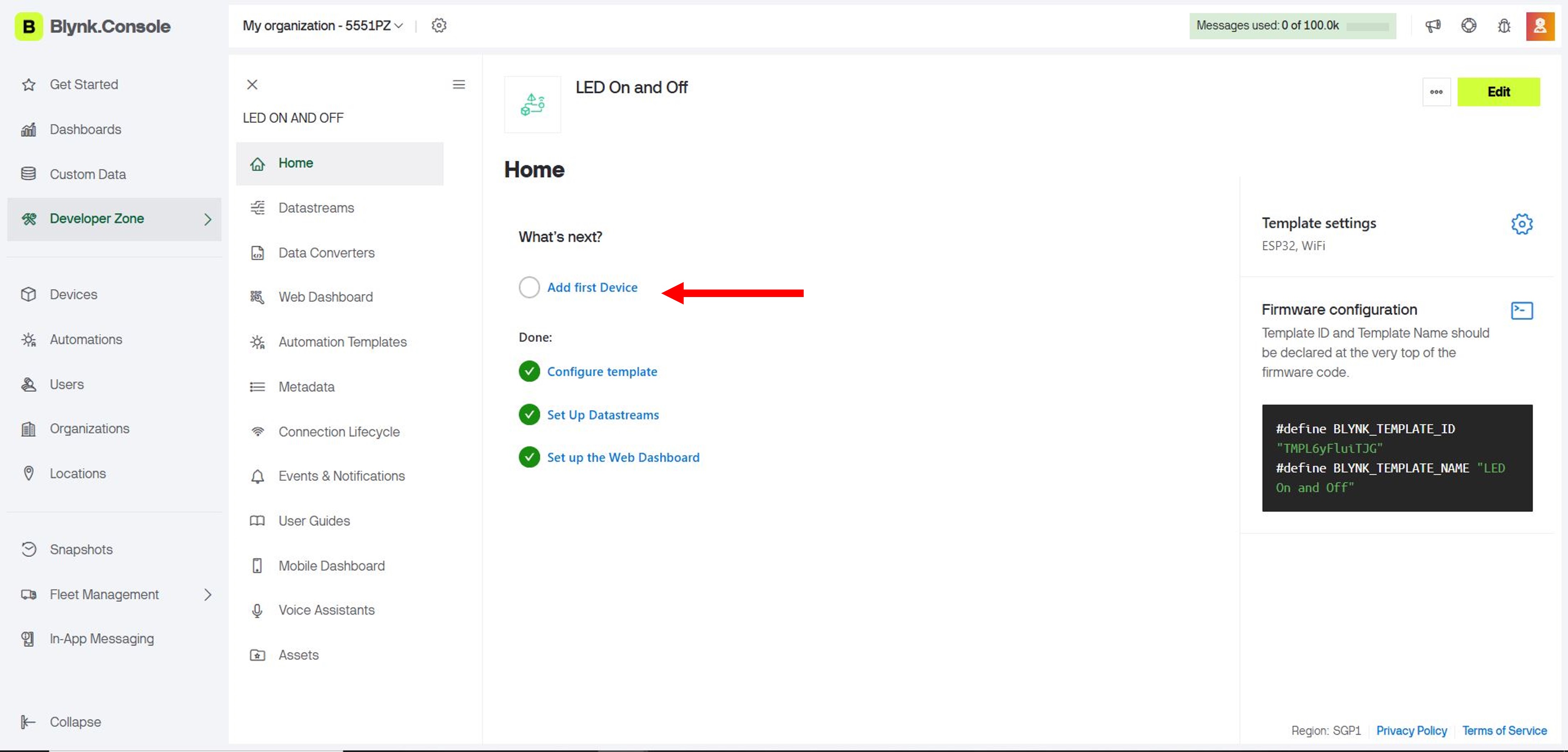
Once the dashboard and widgets are configured, save the template, then register a physical device against it. This generates the unique Auth Token needed in the firmware.
- Click Save at the top-right of the template editor.
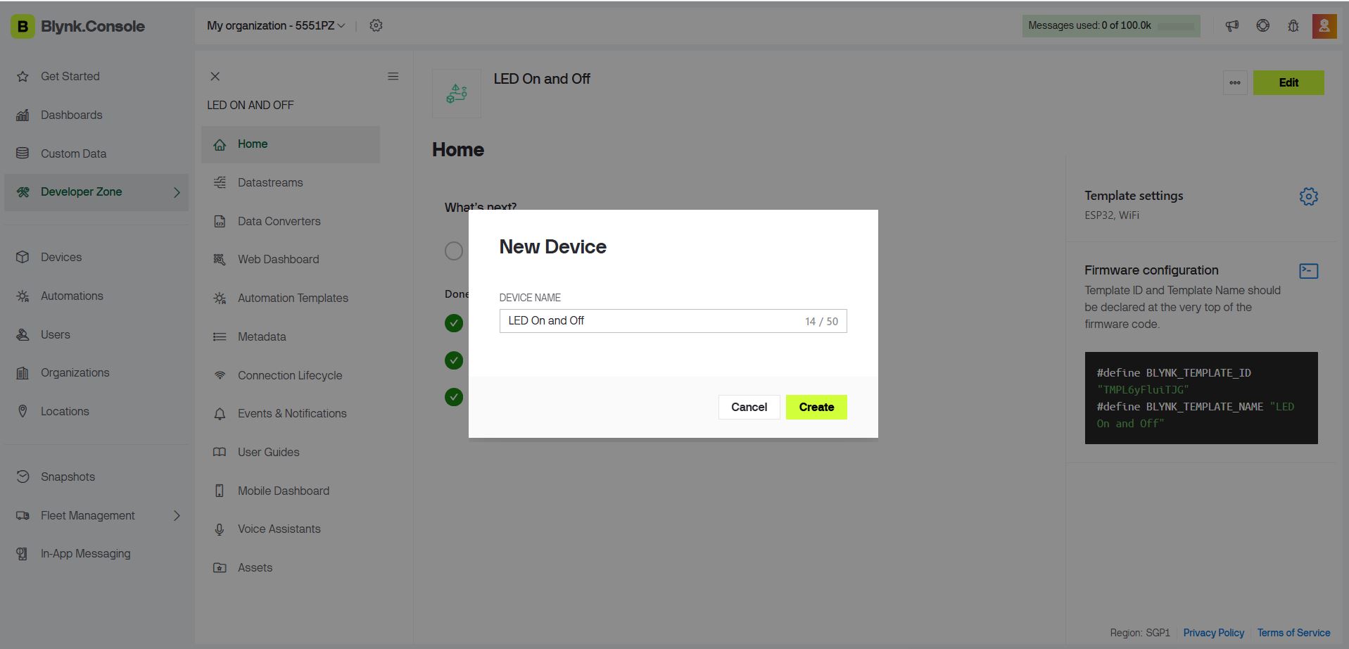
- In the sidebar, click Devices → + New Device.
- Choose From Template and select your template.
- Enter a device name (LED On and Off") and click Create.
- Copy the Template ID, Device Name, and Auth Token — all three are required in the firmware.
Always save your template after changes. Unsaved edits will be lost if you navigate away.
Programming the ESP32 — Arduino IDE
With the device registered, flash firmware to the ESP32 so it connects to Blynk over Wi-Fi and responds to dashboard commands.
Install the Blynk Library
Open the Arduino IDE → Sketch → Include Library → Manage Libraries… → search "Blynk" → install Blynk by Volodymyr Shymanskyy.
Use the Blynk IoT library v1.0.0 or later — not the legacy Blynk library. The two are incompatible and the legacy version will not connect to the current Blynk cloud.
Complete Arduino Sketch
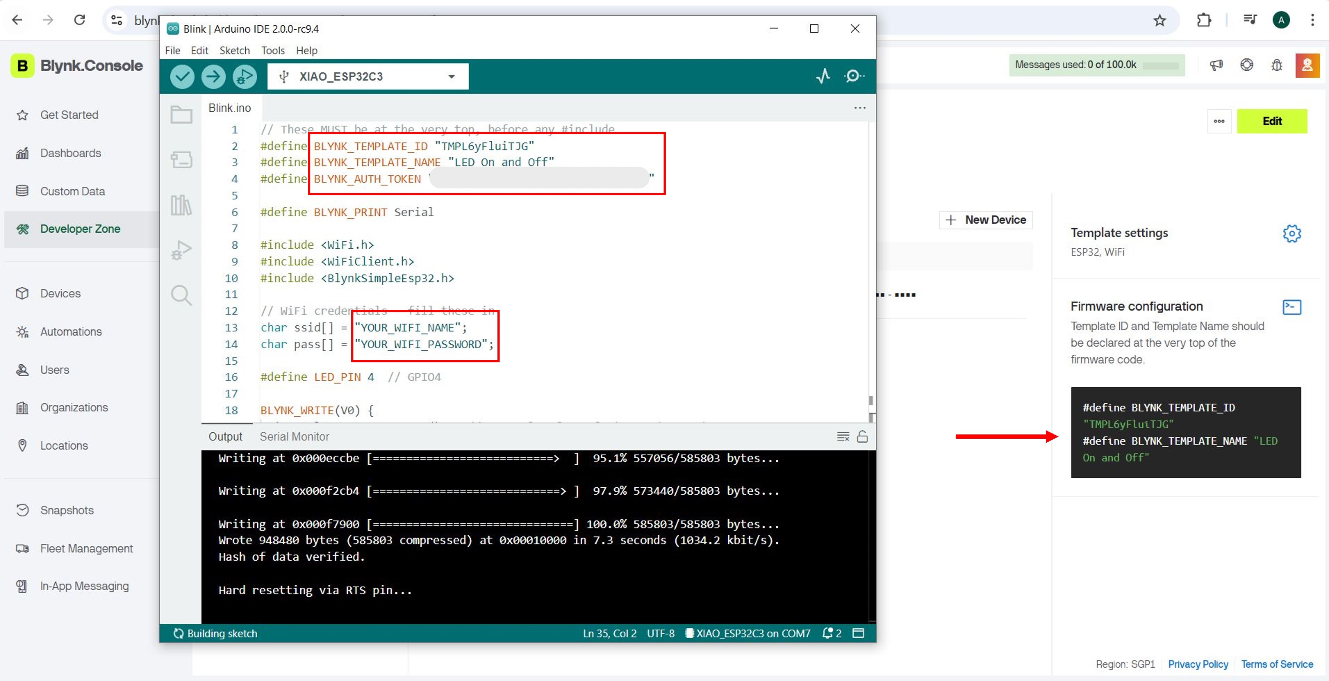
Replace the Wi-Fi credentials and Blynk credentials with the values from your device page.
// These MUST be at the very top, before any #include
#define BLYNK_TEMPLATE_ID   "TMPL6yFluiTJG"
#define BLYNK_TEMPLATE_NAME "LED On and Off"
#define BLYNK_AUTH_TOKEN    "YourAuthTokenHere"
#define BLYNK_PRINT Serial

#include <WiFi.h>
#include <WiFiClient.h>
#include <BlynkSimpleEsp32.h>

// Wi-Fi credentials
char ssid[] = "YourWiFiName";
char pass[] = "YourWiFiPassword";

#define LED_PIN 4  // GPIO 4

// Called whenever the Blynk dashboard writes to Virtual Pin V0
BLYNK_WRITE(V0) {
  int value = param.asInt();    // 0 = OFF, 1 = ON
  digitalWrite(LED_PIN, value);
  Serial.print("LED set to: ");
  Serial.println(value);
}

void setup() {
  Serial.begin(115200);
  pinMode(LED_PIN, OUTPUT);
  digitalWrite(LED_PIN, LOW);   // Start with LED off
  Blynk.begin(BLYNK_AUTH_TOKEN, ssid, pass);
}

void loop() {
  Blynk.run();
}How the code works: BLYNK_WRITE(V0) is a callback that fires automatically whenever the Switch widget changes state. param.asInt() returns 1 (ON) or 0 (OFF), and digitalWrite sets the LED pin accordingly. Blynk.run() in the loop handles all cloud communication — it's the only thing needed there.
Keep your Auth Token private — anyone with it can control your device remotely. Never commit it to a public repository.
Setting Up the Blynk Mobile App
The Blynk mobile app (iOS and Android) mirrors the web dashboard, letting you control your hardware from your smartphone anywhere with an internet connection.
- Download the Blynk IoT app from the App Store or Google Play.
- Sign in with the same account used for the Blynk Console.
- Your device and dashboard appear automatically — no additional setup needed.
- Tap the Switch widget on your phone to toggle the LED on the ESP32.
Both the web dashboard and mobile app communicate with the Blynk cloud simultaneously — a change on one is reflected on the other instantly.
App Tutorial Video
Problems Encountered & How They Were Resolved
1 — Slow or Failed Wi-Fi Connection
The ESP32 took much longer than expected to connect to Blynk, or failed entirely on the lab network. The lab network was blocking Blynk's ports. Fix: Switching to a dedicated 2.4 GHz mobile hotspot resolved the issue immediately. Note: the ESP32 does not support 5 GHz networks.
2 — Wrong Auth Token
The device appeared offline in the Blynk Console even after the ESP32 connected to Wi-Fi. Fix: Regenerated the Auth Token from the Blynk device page and re-uploaded the sketch with the new value.
3 — Incorrect Template ID or Name
The #define values at the top of the sketch must match the Blynk Console exactly, including capitalisation. Fix: Copied the values directly from the console instead of typing them manually.
4 — Library Version Mismatch
Using the legacy Blynk library produced compile errors and failed to connect to the current cloud. Fix: Installed the Blynk IoT library v1.0.0+ via the Library Manager.
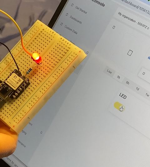
Final Result
With all steps complete, the ESP32 connects to Blynk over Wi-Fi and the LED can be toggled in real time from either the browser dashboard or the smartphone app. The switch on the dashboard instantly reflects the physical LED state, confirming that the full cloud-to-hardware loop is working.
Reflection
This week introduced a completely different layer of the maker stack — the interface layer, where physical hardware becomes remotely accessible through software. Blynk abstracts away a significant amount of networking complexity: instead of setting up a server, configuring sockets, or writing a backend, the entire cloud infrastructure is handled by the platform. This lets you focus on the application logic and UI design.
The biggest practical lesson from this week was network environment awareness. The same firmware that failed on the lab network worked immediately on a mobile hotspot — a reminder that networking issues are often environmental rather than code bugs. Systematic troubleshooting (isolate the variable, test one change at a time) resolved every issue quickly.
For my final project, Blynk's real-time dashboard is directly useful: I can monitor sensor data and trigger actuators remotely without building a custom frontend. The BLYNK_WRITE callback pattern is clean enough to scale to multiple pins and more complex state machines.