Weeks 12 - 13 Mechanism and Machinery
Note, we currently don't have access to edit the group page, so we are posting the group documentation to our indvidual pages.
Group Project Documentation
For two weeks, we are charged with the following group project:
First week
- design a machine that includes mechanism+actuation+automation+function+user interface
- build the mechanical parts and operate it manually
- document the group project and your individual contribution
Second week
- actuate and automate your machine
- document the group project and your individual contribution
- prepare a demonstration of your machines for the next class
Individual Project documentation
For the first week, I designed, prototyped, and then redesigned and assembled the x and y axes, the rack and pinion gears, and the y and x axis gantries, and the z axis stepper mount and end effector.
My first task- Build out the x axis.
We used as inspiration the following:
CircuitsArduino, MertArduinoin. “Arduino Mini CNC Plotter.” Instructables. Accessed April 8, 2026. https://www.instructables.com/Arduino-Mini-CNC-Plotter/.
Downloaded the x end motor file from Prusa Mk3s to see how they attached the stepper motor.
Printables.Com. “I3 MK3S+ Printable Parts by Prusa Research | Download Free STL Model.” Accessed April 10, 2026. https://www.printables.com/model/57217-i3-mk3s-printable-parts.
I sketched out some ideas:
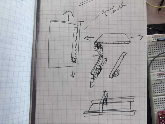
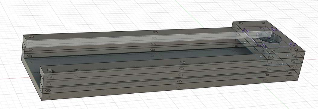
Designed in fusion
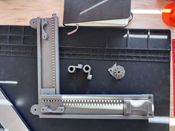
I worked first on gears and gantries.
To build a rack gear, I decided that I would use the following:
Gears
I used the gear extension for fusion.
https://apps.autodesk.com/FUSION/en/Home/Index
installation/download page
https://apps.autodesk.com/FUSION/en/Detail/Index?id=1259509007239787473&os=Win64&appLang=en
(note, only works in Hybrid mode in Fusion).
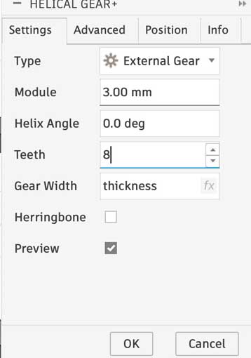
To create a rack and pinion gear system, choose gear add in solid>create>helix great
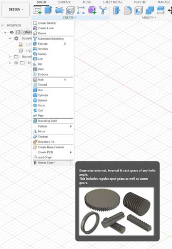
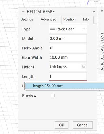
Choose the rack gear from the dropdown
Change helix angle to 0 degree
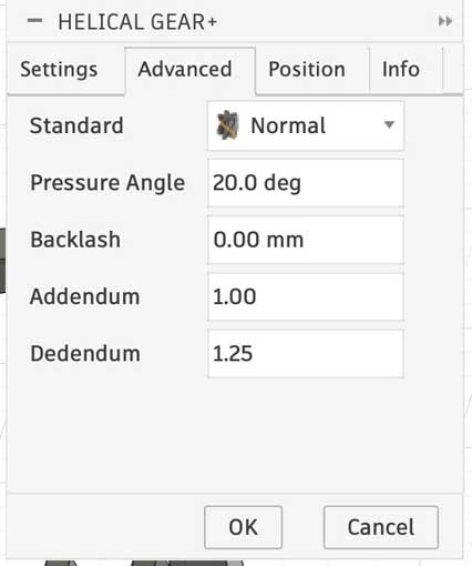
The settings for the rack gear are:
The settings for the pinion gear are:
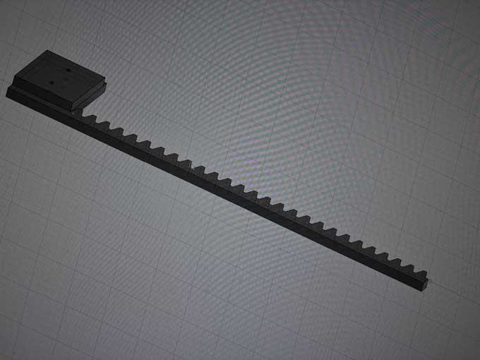
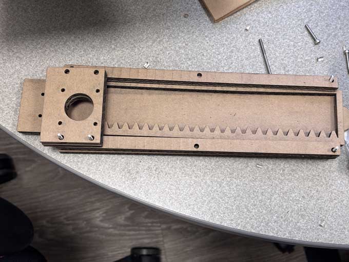
rack gear early prototype
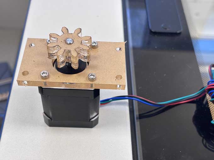
pinion gear
X and Y gantries
I designed the gantries in 6 mm thick layers, using parametric design. The goal is to use one sheet of acrylic (12 in x 24 in) and fasten the layers with m3 bolts.
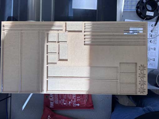
I cut an example in cardboard as a prototype-
I used chatgpt to dictate my thoughts on the project as I was assembling the cardboard x and y gantries to make a running list of changes I need to make. The prompt was "I need for you to make a list of and not respond until I tell you to. I'm making a list of things I need to change in a project I'm working on." BTW- this doesn’t work very well as Chatgpt really wants to interject- like an eager five year old.
The list I dictated to Chatgpt was:
Consolidated Change List (Project Adjustments)
Fasteners & Mounting
Change bolt orientation from vertical to horizontal alignment along length
Set consistent distance between bolts
Standardize bolt widths across X and Y axis connections. Adjust bolt diameters- after test
Ensure consistent spacing of bolt holes from edges
Inset bolts at axis ends to prevent interference with movement
Account for bolt head height in base design (countersink or recess)
Consider smaller bolts that thread directly into plastic (no nuts)
In attaching the servo, replace M3-20 screws with shorter M3 screws
Confirm stepper motor hole pattern and spindle hole are accurate
Structural Components
Create a base to support the unconnected end of the X-axis (prevent droop)
Make spacer, lip, and base widths consistent
Remove one layer from motor holder and add a second spacer layer
Decrease width of servo holder
Design next iteration of X and Y axis motor mounts (label clearly)
Gear System
Increase gear height
Increase gear holder height (must exceed spacer + lip height)
Improve connection between X motor holder and rack gear
Address friction in gear system
Spacing & Motion
Add thin intermediary layer (e.g., paper or similar) between lip and spacer to reduce friction
Integrate this layer into lip geometry if possible (avoid extra part)
Increase spacing to account for compression from stepper motor weight
Motor & Material Constraints
Stepper motor weight compresses layers → increase clearance
Stepper uses M3 bolts
Material thickness: ~6.5–6.7 mm
Two material layers appropriate for servo mounting
Servo shaft length slightly > 20 mm
I worked through the punchlist of changes, making them in the fusion files.
Much of this has to do with the hardware on hand. I only have available button head screws and laser cutters can't really counter-sink screw heads, which limits the range of motion of the x axis.
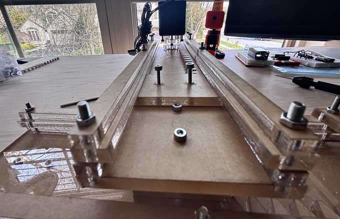
I used nylon washers between the spacer layer and the lip to increase the space for the rack gear to slide. I added five layers to the y axis so that the x axis gantry could clear the bolts and side of the y gantry.
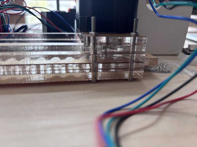
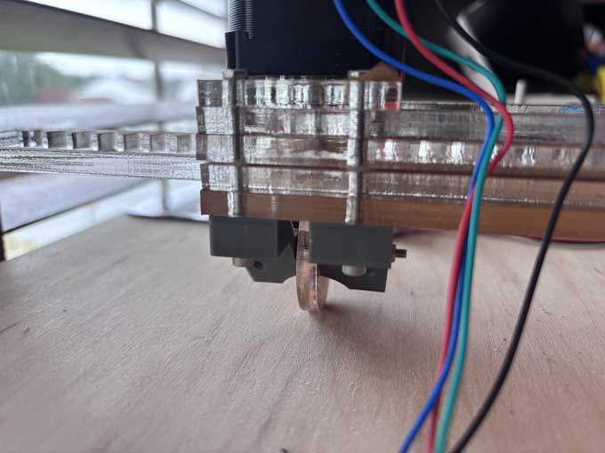
Rather than create a laser cut wheel holder, I laser cut the wheel itself and then designed and 3d printed the wheel for the x axis. I used spacers and a shoulder bolt to reduce friction.
I used copper heat inserts to anchor the servo/end effector and to anchor the x axis gantry to the y axis gantry.
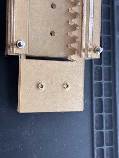
I had to use a handheld drill to clean out the plastic that seeped into the threads.
The last thing I need to do is add a servo to control the end effector – the z axis on the plotter. Given the process physics of laser cutting materials, it makes more sense to 3d print the attachment from the x-axis rack and the servo. Likewise, I will not laser cut the pen holder.
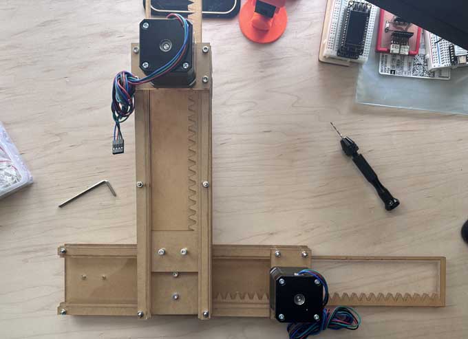
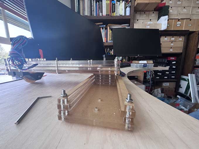
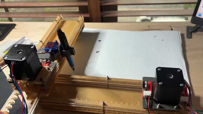
plotter being assembled
Plotter x-axis
Plotter y-axis
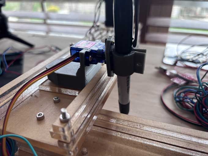
Z-axis
Things I would do differently
Replace button head bolts with flathead bolts.
Reduce the friction between the base and rack gear
Meeting with Instructor
We met with our instructor, Terence, who approved of the design and gave us tips on how to proceed. Problems we noted include:
Given the board we’ve chosen, it is unclear how to use a servo in lieu of a stepper for the z-axis,.
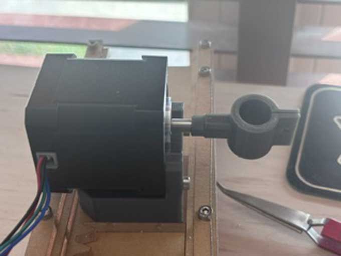
The placement of the x-axis stepper at the end of the gantry over the wheel adds unwanted stress on the gantry and could negatively affect its use.
We don’t have enough end stops to control the range of motion of the x and y axes.
We now have to automate and actuate the machine- which we opted to use GRBL and Universal G-Code Sender.
Revisions
I purchased flat head M3 screws to attach the x gantry to the y gantry, and used a hand drill to counter sink the screw head.
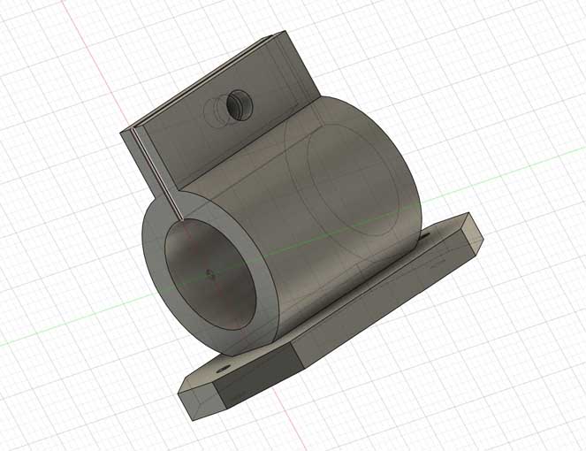
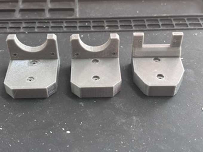
I redesigned the z axis mount to hold a stepper and redesigned the end effector to accommodate a stepper rather than a servo:
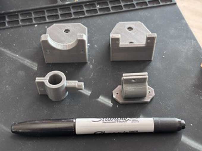
I tried to mount the servo and end effector but they were the wrong size. I designed them again to better match the dimensions of the stepper and the machine. I went through a few iterations as I had not measured correctly.
Lesson learned: measure twice, cut once.
Electronics- control and servos
There is no datasheet or pinout for the materials we purchased and no instructions. This might have been a mistake
Lesson learned- when buying components, make sure that the manufacturer provides a datasheet and instructions.
I watched the following videos/tutorials online
CircuitsArduino, MertArduinoin. “Arduino Mini CNC Plotter.” Instructables. Accessed April 8, 2026. https://www.instructables.com/Arduino-Mini-CNC-Plotter/.
DIY Engineers. GRBL with Arduino CNC Shield – Complete Guide. 2023. 31:36. https://www.youtube.com/watch?v=Xlkmso01vUk.
jtechcustoms. CNC Shield, Arduino UNO, DRV8825 - Tips for Success! 2020. 08:02. https://www.youtube.com/watch?v=OfyT1xTZC6o.
jtechcustoms. Setup Arduino UNO, CNC Shield v3, GRBL, and Related CNC Motion Components and Electronics. 2020. 13:31. https://www.youtube.com/watch?v=hL2NtjQiJ5w.
Kruger, Bertus. “Arduino CNC Shield V3.XX – Assembly Guide.” Protoneer.Co.Nz, September 29, 2013. https://blog.protoneer.co.nz/arduino-cnc-shield-v3-00-assembly-guide/.
William L. Weaver. Initial Test of 3 Stepper Motors and Arduino UNO / CNC Shield. 2023. 01:53. https://www.youtube.com/watch?v=AMu95mCpHms.
WorkshopCNC, EricAusomein. “3020 CNC + Arduino + GRBL + CNC Shield V3.” Instructables. Accessed April 13, 2026. https://www.instructables.com/3020-CNC-Arduino-GRBL-CNC-Shield-V3/.
I then googled the part number on the stepper to determine the specs, which are:
Specification: Model Number: 17HD48002H-22B Current / Phase: 1.7A Phase: 2 Size: 42*42*48mm Step Angle(degrees): 1.8 Holding Torque: 0.59 N.m Shaft Diameter: 4.5 mm
Source- “Stepper Motor Nema 17 17HD48002H.” Accessed April 18, 2026. https://dynamic.me/stepper-motor-nema-17-17-dh-48002-h.
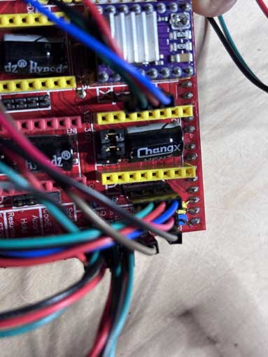
I attached the CNC shield to the fake Arduino and mounted the heat shields (rather poorly) on the boards and then mounted them to the CNC shield.
IMPORTANT- the stepper drivers are designed so that they should only run when a stepper is attached to them. Without a stepper motor connected, the stepper driver will over-heat. You’ll fry your driver.
According to the amazon description, the servos require 12 volts. I used a variable power source to power the shield and a barrel jack to wire adaptor to connect the power source to the CNC shield.
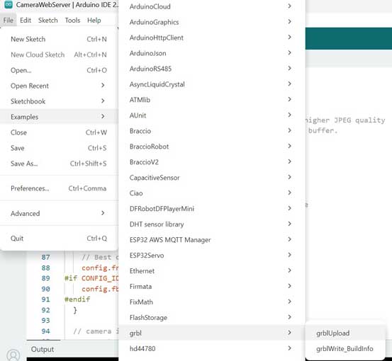
I downloaded the GRBL library and added it to Arduino. In the GRBL examples library, I uploaded to the Arduino knockoff the examples>grbl.grblupload.ino sketch.
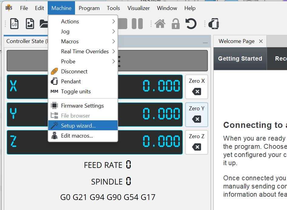
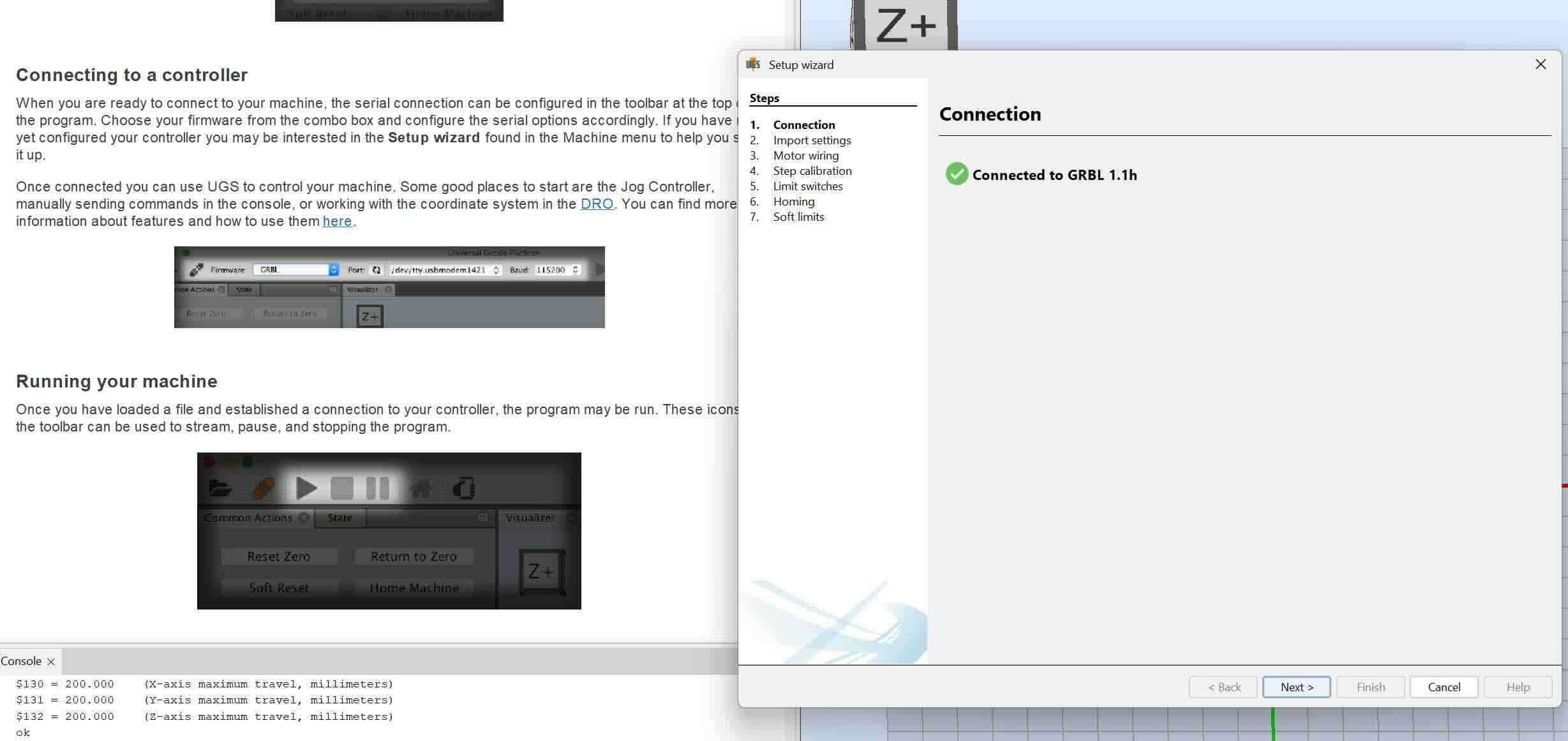
I then downloaded Universal G-Code Sender to my PC, installed it, and connected my Arduino to the software.
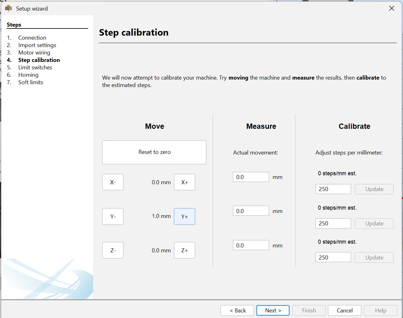
I used the wizard to work through setting up the machine. I worked through the wizard to calibrate the machine.
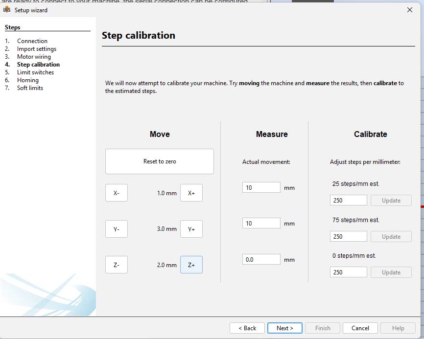
I stopped at this point as my z axis will not be linear motion, but rather an end-effector rotating a pen to either touch the paper or not.
I controlled the x and y axes by jogging the plotter.
My next step is to learn about g-code and revise the g-code on the stepper so that I set limits to the movement, define an up and down state for the z-axis using a servo rather than a stepper, and figure out how to send g-code of an image to the plotter.
When we next met with our instructor, we reviewed the x and y gantry and our project to date.Our instructor, Terence, approved of the design and gave us tips on how to proceed. Problems we noted include:
- It is unclear how to use a servo in lieu of a stepper for the z-axis, given the board we’ve chosen.
- The placement of the x-axis stepper at the end of the gantry over the wheel adds unwanted stress on the gantry and could negatively affect its use.
- We have to control the range of motion of the x and y axes (and we don’t have enough end stop switches).
- We now have to automate and actuate the machine- which we opted to use GRBL and Universal G-Code Sender. We need to understand how those work.
- We don’t know if we have the permissions to create a page on the UNCCSFL lab site for our group project documentation.
- We need to create a video and slide of the project and post it to our group page and as a comment on Issue #8.
Heaven had posted on Mattermost questions on GRBL and the design of the machine’s electronics. Instructors recommended that the stepper is too heavy and overpowered for the z-axis end effector. I swapped out the new parts for the old.
They also suggested to:
- Adjust the trim pots on the CNC shield to tune the current for the motors, based on Rico’s recommendations.
- Adjust the stepper drivers to activate micro-stepping on the servos, based on Rico’s recommendations.
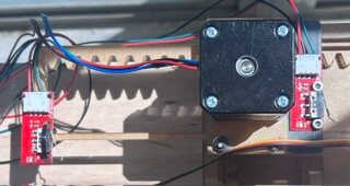
After our meeting and feedback from the instructors, I revised the machine to reduce the weight on the x gantry and reduce the torque caused by the stepper motors. I moved the x-axis gantry so that it was mounted over the connection to the y-axis gantry. I added a washer and nut under the mount to accommodate the height of the servo
If I were to do this again, I would add two additional screw holes on both sides of each gantry to better facilitate this.
I referred to this video before I started.
Rachel De Barros. Control a NEMA 17 Stepper Motor with A4988 Driver and Arduino - Full Guide. 2025. https://www.youtube.com/watch?v=wcLeXXATCR4.
I used the jumper shunts that came with the board to activate micro-stepping.

I opted for 1/32 step as I want less torque.
Then I used the following tutorial and image to wire the servo motor to the shield.
sandeep. “GRBL CNC Shield + Z Axis Servo MIGRBL.” Electric DIY Lab, August 7, 2019. https://electricdiylab.com/grbl-cnc-shield-z-axis-servo-migrbl/.
Michael Klements. How To Correctly Set The Motor Current Limit On An A4988 Stepper Motor Driver. 2020. 04:50. https://www.youtube.com/watch?v=OpaUwWouyE0.
sandeep. “GRBL CNC Shield + Z Axis Servo MIGRBL.” Electric DIY Lab, August 7, 2019. https://electricdiylab.com/grbl-cnc-shield-z-axis-servo-migrbl/.
I attempted to use a multimeter to measure the current that the board was putting out, but the multimeter would not register any voltage when I used it. As a result, I assumed that the middle of each trimpot would be about right.
The plotter would continually run up against the gantry when running, which would likely break the acrylic gears or burn out the stepper. I needed to add end stops. I eventually settled on zip tying the x and y positive end stop switches to the end of the rack gear piece.
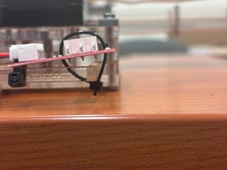
It is inelegant, but works for now.
I then created a mount to be placed on both gantry that would accommodate the negative end stops.
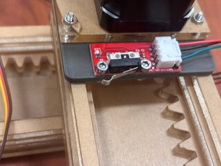
If there was time, I would redesign the end of the rack to be taller so that it would hit an end stop mounted on the gantry.
Testing
I created a simple circle as an SVG file and attempted to convert it to G-code using the Mods environment. I initially exported the SVG as a PNG to use with a Gerber plot module, generated an outline, saved the file, and tried to load it into Universal Gcode Sender. I realized this approach was incorrect and switched to using the Mods draw program with the original SVG, but when Mods did not produce usable results, I abandoned that workflow.
I then opened the SVG in Inkscape and followed a tutorial to use the G-code extensions (Gcodetools ). I converted the SVG object into a path and attempted to run “Path to G-code,” where I encountered an error indicating that no layers existed. I created a layer, ensured the path was placed on that layer, and used the set orientation points function. Running the tool again produced a warning about an undefined cutting tool, which I allowed to default, followed by an error indicating that the output directory did not exist.
I resolved this by creating and configuring a valid output directory in preferences, after which I successfully generated the G-code file. You have to set the directory that you want the file to be downloaded in. I also kept the add numeric suffix to the filename to keep track of all of the different g-code I created.
I ran the orientation points function, and then the path to g-code function. Inkspace then exported a g-code file to the specified directory.
Finally, I opened Universal Gcode Sender, uploaded the generated G-code file, and, eventually, executed it successfully.
The first few versions didn’t work because the build area of the plotter is fairly small-ish- about 150 mm x 150 mm. The UGS would continually raise an error because the device would go out of the work area and/or trigger an end stop.
I revised the size of the image to be in mm and within the size of the 150 mm x 150 mm work area.
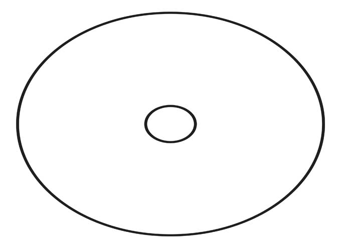
We are in business.
I then wanted to test a more elaborate image. I used a png of my institution's logo and followed the same process.
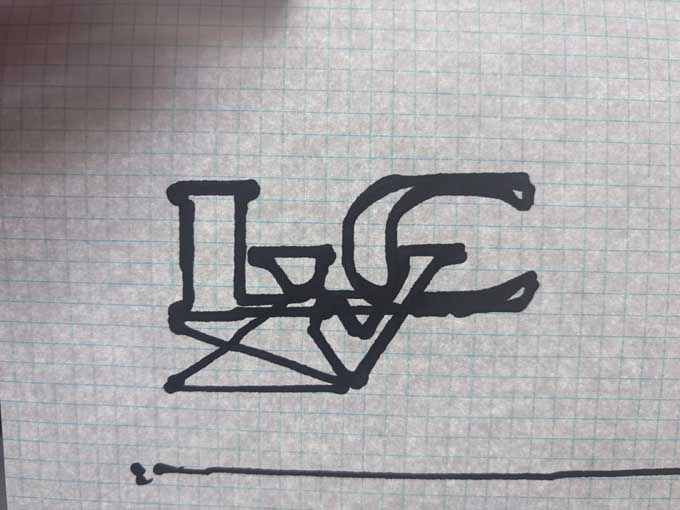
Success!
I created the slide for the group as well as the group documentation.
This week's Files
- base.svg
- circletest.svg
- endeffector.3mf
- endeffectorv3.3mf
- endstop holder.3mf
- Healiacal Gear (8R@0.00 m=3.0).svg
- Healiacal Rack (254.00000000000003mm R@0.00 m=3.0).svg
- leftlip.svg
- leftspacer.svg
- logo_0007.ngc
- motorholdera.svg
- output_0009.ngc
- rightlip.svg
- rightspacer.svg
- spacer2.svg
- spacer2lft.svg
- spacer2rt.svg
- spacerlft.svg
- spacerrt.svg
- testSVG.svg
- wheel.svg
- wheelv3.3mf
- zaxisv4.3mf