Assignments
Week 11 - Networking and Communications
Group Assignment
- Send a message between two projects.
Individual Assignment
- Design, build, and connect wired or wireless node(s) with network or bus addresses and local input and/or output device(s).
Summary - Group Assignment
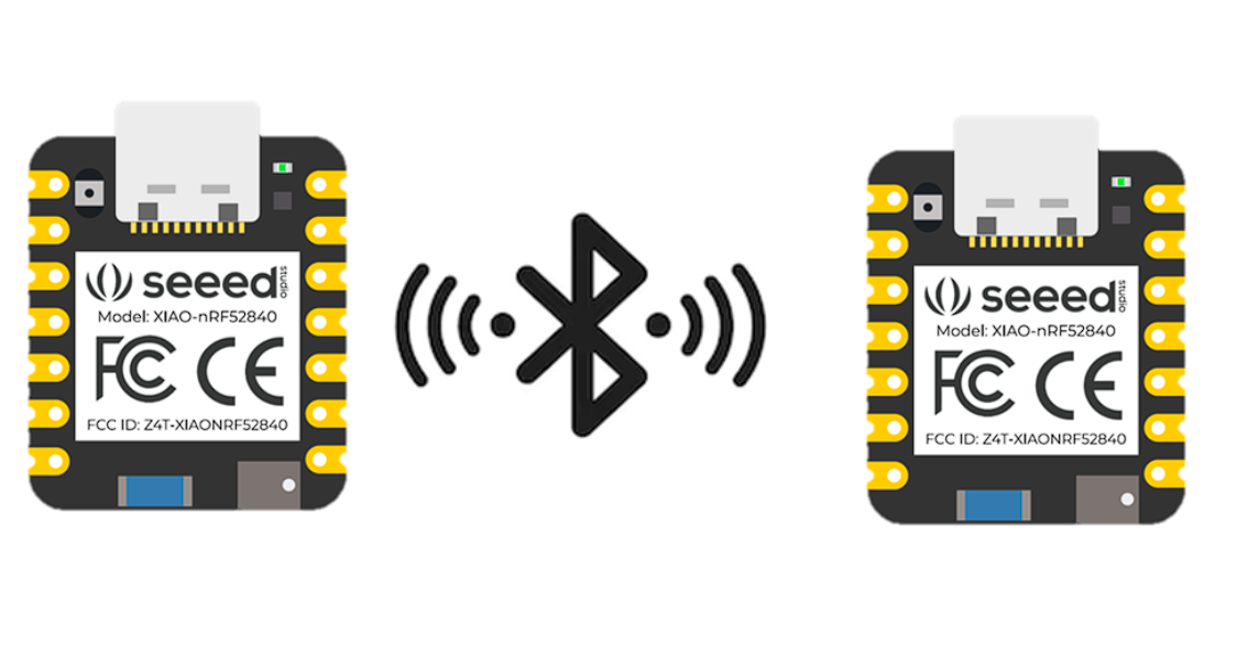
In the group assignment, we explored communication between two XIAO nRF52840 boards by configuring one as a sender and the other as a receiver. Each board had a button and an LED, and pressing a button on one PCB turned on the LED on the other, demonstrating real-time data exchange. The schematic design of the board was developed in Week 6, and the fabrication process was completed in Week 8.
This allowed us to understand how embedded systems interact within a network, highlighting the importance of correct wiring, protocol selection, and synchronization for stable communication between microcontrollers.
🔗 If you want to explore the Group Assignment in more detail, you can visit the official Fab Academy page:
Visit Fab Academy ULima →BLE Architecture and Operation
The system was implemented using a Central–Peripheral architecture, which is the core communication model in Bluetooth Low Energy (BLE). In this configuration, one XIAO board acted as the Peripheral device, while the other functioned as the Central device. This setup allowed both boards to establish a wireless connection and exchange data in real time.
The Peripheral operates as a server. It continuously advertises its presence using BLE signals, making itself visible to nearby devices. Inside this device, a BLE Service is created, and within that service, a Characteristic is defined. The characteristic is the key element, as it stores the data that will be shared between devices.
XIAO nRF52840 Peripheral
#include <ArduinoBLE.h>

const int BUTTON_PIN = D2;     // button on the peripheral
const int LED_PIN    = D9;     // optional local LED for testing

BLEService buttonService("180C");
BLEByteCharacteristic buttonChar("2A56", BLERead | BLENotify);

byte lastButtonState = 0;

void setup() {
  pinMode(BUTTON_PIN, INPUT_PULLUP);
  pinMode(LED_PIN, OUTPUT);
  digitalWrite(LED_PIN, LOW);

  Serial.begin(9600);
  while (!Serial);

  if (!BLE.begin()) {
    Serial.println("BLE failed to start");
    while (1);
  }

  BLE.setLocalName("XIAO_PERIPHERAL");
  BLE.setAdvertisedService(buttonService);

  buttonService.addCharacteristic(buttonChar);
  BLE.addService(buttonService);

  buttonChar.writeValue((byte)0);

  BLE.advertise();
  Serial.println("Peripheral advertising...");
}

void loop() {
  BLEDevice central = BLE.central();

  if (central) {
    Serial.print("Connected to central: ");
    Serial.println(central.address());

    while (central.connected()) {
      byte currentButtonState = (digitalRead(BUTTON_PIN) == LOW) ? 1 : 0;

      if (currentButtonState != lastButtonState) {
        buttonChar.writeValue(currentButtonState);

        if (currentButtonState == 1) {
          digitalWrite(LED_PIN, HIGH);
          Serial.println("Button pressed - sent 1");
        } else {
          digitalWrite(LED_PIN, LOW);
          Serial.println("Button released - sent 0");
        }

        lastButtonState = currentButtonState;
      }

      delay(20);
    }

    Serial.println("Central disconnected");
    digitalWrite(LED_PIN, LOW);
  }
}
Each service and characteristic is identified using a UUID (Universally Unique Identifier), which acts as a unique address. These identifiers allow the Central device to locate and access specific data within the Peripheral.
- Peripheral role: Provides data and waits for connections.
- Central role: Scans, connects, and interacts with the Peripheral.
- Service: Container that organizes related data.
- Characteristic: Variable used to store and transmit values.
- UUID: Unique identifier used to locate services and characteristics.
The Central device begins by scanning the environment for BLE devices. Once it detects the Peripheral, it establishes a connection and accesses its services using the corresponding UUIDs. After connecting, the Central can read or write values to the characteristic.
XIAO nRF52840 Central
#include <ArduinoBLE.h>

const int LED_PIN = D8;   // LED on the central

BLEDevice peripheral;
BLECharacteristic buttonChar;

void setup() {
  pinMode(LED_PIN, OUTPUT);
  digitalWrite(LED_PIN, LOW);

  Serial.begin(9600);
  while (!Serial);

  if (!BLE.begin()) {
    Serial.println("BLE failed to start");
    while (1);
  }

  Serial.println("Central scanning for peripheral...");
  BLE.scan();
}

void loop() {
  peripheral = BLE.available();

  if (peripheral) {
    if (peripheral.localName() == "XIAO_PERIPHERAL") {
      BLE.stopScan();

      Serial.print("Found peripheral: ");
      Serial.println(peripheral.localName());

      if (connectToPeripheral(peripheral)) {
        Serial.println("Connected successfully");

        while (peripheral.connected()) {
          if (buttonChar.valueUpdated()) {
            byte value;
            buttonChar.readValue(value);

            if (value == 1) {
              digitalWrite(LED_PIN, HIGH);
              Serial.println("Received 1 - LED ON");
            } else {
              digitalWrite(LED_PIN, LOW);
              Serial.println("Received 0 - LED OFF");
            }
          }

          delay(20);
        }

        Serial.println("Peripheral disconnected");
        digitalWrite(LED_PIN, LOW);
      }

      BLE.scan();
    }
  }
}

bool connectToPeripheral(BLEDevice peripheral) {
  Serial.println("Connecting...");

  if (!peripheral.connect()) {
    Serial.println("Connection failed");
    return false;
  }

  Serial.println("Discovering attributes...");

  if (!peripheral.discoverAttributes()) {
    Serial.println("Attribute discovery failed");
    peripheral.disconnect();
    return false;
  }

  buttonChar = peripheral.characteristic("2A56");

  if (!buttonChar) {
    Serial.println("Characteristic not found");
    peripheral.disconnect();
    return false;
  }

  if (!buttonChar.canSubscribe()) {
    Serial.println("Characteristic is not subscribable");
    peripheral.disconnect();
    return false;
  }

  if (!buttonChar.subscribe()) {
    Serial.println("Subscription failed");
    peripheral.disconnect();
    return false;
  }

  Serial.println("Subscribed to characteristic");
  return true;
}- Advertising: Peripheral sends signals to be discovered.
- Scanning: Central searches for available devices.
- Connection: A communication link is established.
Communication between both devices occurs through the characteristic. When an event is triggered, such as pressing a button, a value is written to the characteristic. This value is transmitted wirelessly to the connected device, which continuously monitors the characteristic for changes.
- Data transmission: Values are written to the characteristic.
- Reception: The other device detects the change.
- Response: The device executes an action, such as turning an LED on or off.
Unlike traditional wired communication, BLE does not send electrical signals directly between devices. Instead, it exchanges structured digital data through services and characteristics. This approach makes BLE a scalable and efficient protocol for wireless embedded systems.
Overall, this system demonstrates how two independent microcontrollers can communicate wirelessly by sharing data through defined structures, forming the basis for more advanced systems such as IoT networks.
Summary – Individual Assignment
In this individual assignment, I explored several communication protocols for embedded systems, including UART, I2C, SPI, and BLE. These experiments allowed me to understand how devices exchange data through wired and wireless connections.
The main focus of my work was BLE communication between two XIAO nRF52840 boards, where one acted as a Peripheral and the other as a Central, enabling real-time wireless interaction.
This assignment helped me strengthen my understanding of communication architectures, protocol behavior, and data exchange in networked systems. The schematic design of the board was developed in Week 6, and the fabrication process was completed in Week 8.
Communication Protocols
In this week, I explored different communication protocols used in embedded systems. Each protocol has different characteristics depending on the type of connection, speed, and number of devices involved.
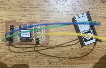
UART Communication: XIAO nRF52840 and ESP32
I implemented UART communication between a XIAO nRF52840 and an ESP32 by cross-connecting TX and RX pins with a shared ground. The system was tested using one-way data transmission from the XIAO to the ESP32.
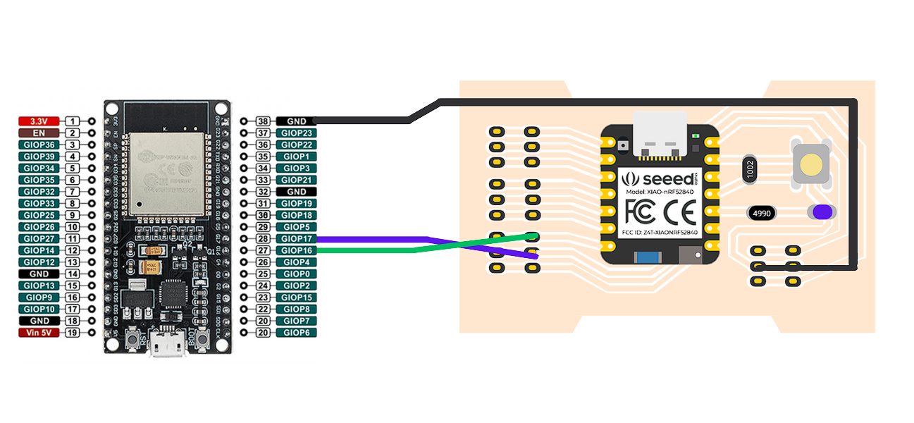
Connections
| From | To |
|---|---|
| XIAO D6 (TX) | ESP32 GPIO16 (RX) |
| XIAO GND | ESP32 GND |
To test the connection, I uploaded a program to the XIAO that continuously sends a message through UART. On the ESP32, I used a receiver program that reads the incoming data and prints it in the Serial Monitor.
This experiment helped me understand the importance of cross-connecting TX and RX, using a common ground, and selecting the correct UART pins. I also learned that some ESP32 pins are input-only and cannot be used for communication.
XIAO nRF52840 Code (Sender)
#include <Adafruit_TinyUSB.h>

void setup() {
  Serial.begin(9600);
  Serial1.begin(9600);
}

void loop() {
  Serial1.println("Hello from XIAO, UART");
  delay(1000);
}
ESP32 Code (Receiver)
// ESP32 - UART Receiver

HardwareSerial mySerial(1);  // Use UART1

void setup() {
  Serial.begin(9600);
  mySerial.begin(9600, SERIAL_8N1, 16, 17);
  // RX = GPIO16
  // TX = GPIO17
}

void loop() {
  if (mySerial.available()) {
    String message = mySerial.readStringUntil('\n');
    Serial.print("Received: ");
    Serial.println(message);
  }
}
Result
When the communication worked correctly, the ESP32 Serial Monitor displayed the received message continuously:
Received: Hello from XIAO, UART
Received: Hello from XIAO, UART
Received: Hello from XIAO, UART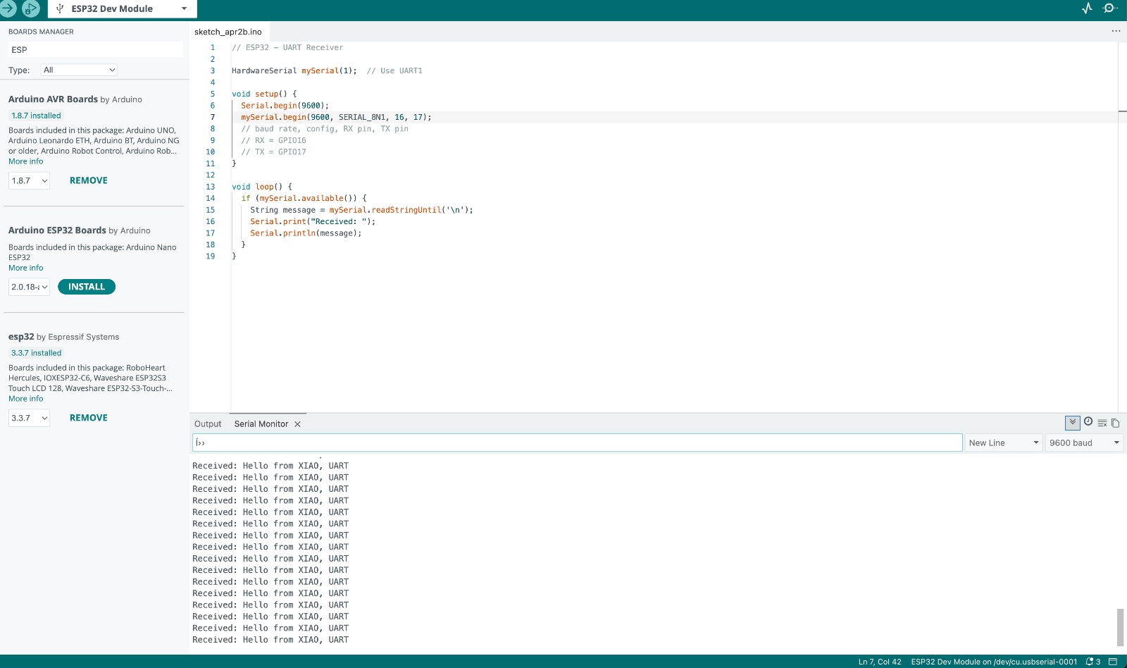
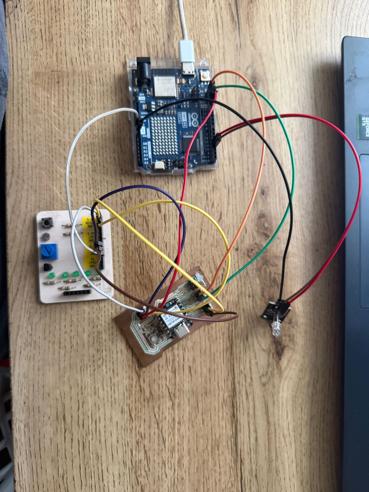
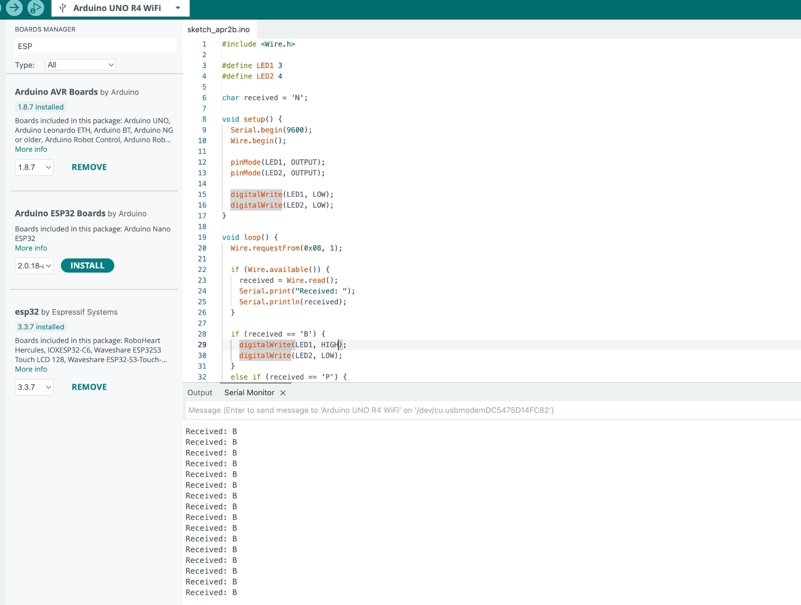
I2C Communication
In this assignment, I implemented I2C communication between two microcontrollers using a
master-slave architecture. The Arduino Uno R4 was configured as the master device, while the
XIAO nRF52840 acted as the slave with address 0x08.
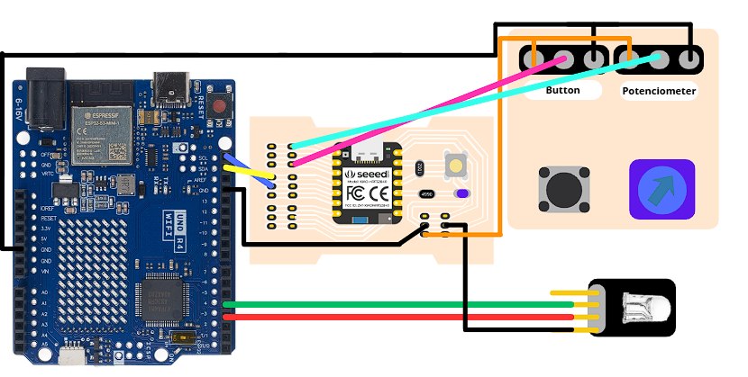
In this implementation, input devices were connected to the slave. A push button and a potentiometer were used to generate interaction data. The XIAO reads these inputs and sends a message to the Arduino, which then processes the information and controls two LEDs.
Pin Configuration
XIAO nRF52840 (Slave)
| Component | Pin |
|---|---|
| Button | D2 |
| Potentiometer (middle pin) | A0 |
| SDA (I2C Data) | D4 |
| SCL (I2C Clock) | D5 |
| GND | GND |
Arduino Uno R4 (Master)
| Component | Pin |
|---|---|
| LED 1 | Pin 3 |
| LED 2 | Pin 4 |
| SDA (I2C Data) | SDA |
| SCL (I2C Clock) | SCL |
| GND | GND |
XIAO nRF52840 Code (Slave)
#include <Wire.h>
#define BUTTON_PIN 2
#define POT_PIN A0
char message = 'N';
int lastPotValue = 0;
void setup() {
pinMode(BUTTON_PIN, INPUT_PULLUP);
Wire.begin(0x08);
Wire.onRequest(requestEvent);
}
void loop() {
int buttonState = digitalRead(BUTTON_PIN);
int potValue = analogRead(POT_PIN);
if (buttonState == LOW) {
message = 'B';
}
else if (abs(potValue - lastPotValue) > 20) {
message = 'P';
}
else {
message = 'N';
}
lastPotValue = potValue;
delay(50);
}
void requestEvent() {
Wire.write(message);
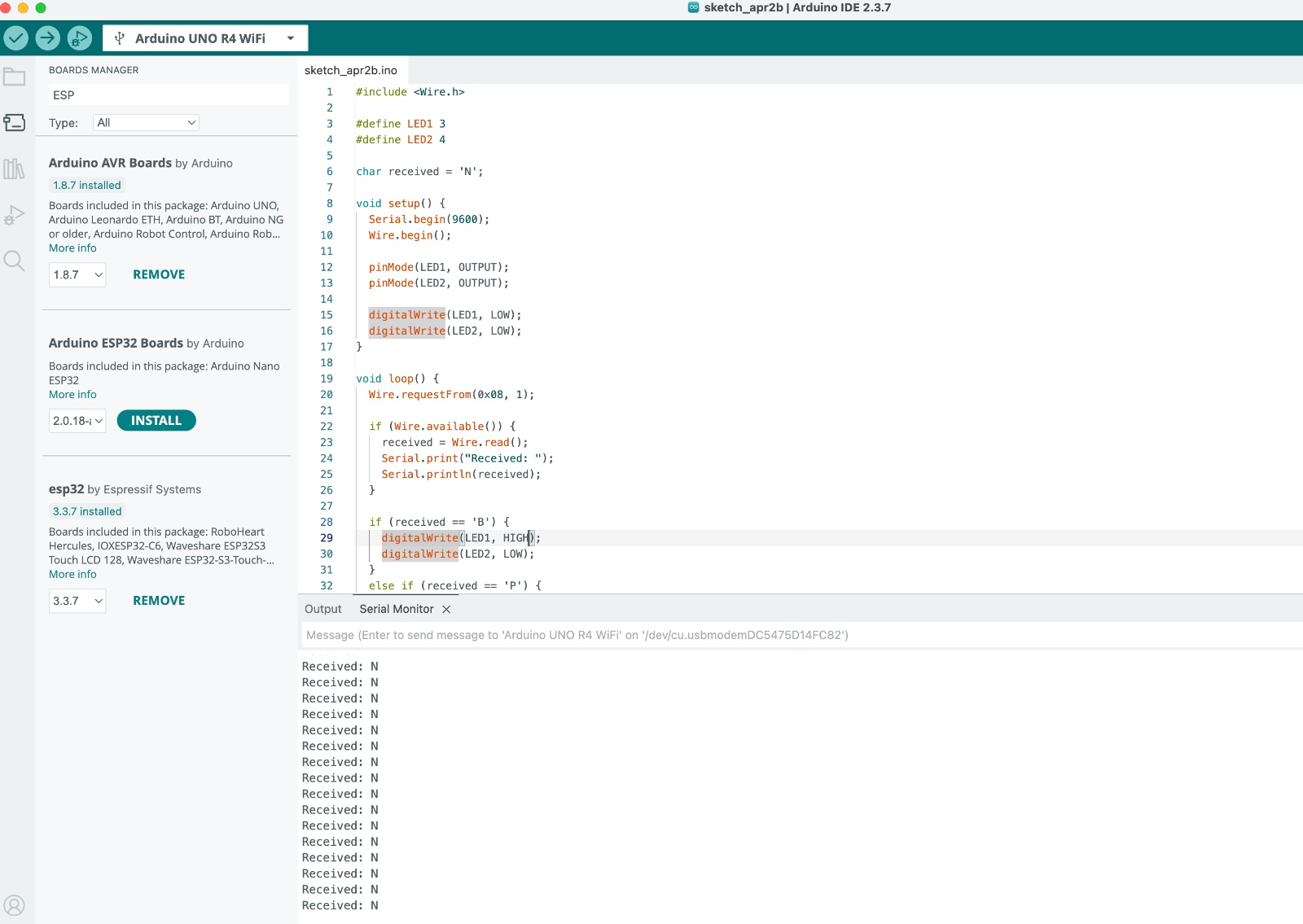
}Arduino Uno R4 Code (Master)
#include <Wire.h>

#define LED1 3
#define LED2 4

char received = 'N';

void setup() {
  Serial.begin(9600);
  Wire.begin();

  pinMode(LED1, OUTPUT);
  pinMode(LED2, OUTPUT);

  digitalWrite(LED1, LOW);
  digitalWrite(LED2, LOW);
}

void loop() {
  Wire.requestFrom(0x08, 1);

  if (Wire.available()) {
    received = Wire.read();
    Serial.print("Received: ");
    Serial.println(received);
  }

  if (received == 'B') {
    digitalWrite(LED1, HIGH);
    digitalWrite(LED2, LOW);
  }
  else if (received == 'P') {
    digitalWrite(LED1, LOW);
    digitalWrite(LED2, HIGH);
  }
  else {
    digitalWrite(LED1, LOW);
    digitalWrite(LED2, LOW);
  }

  delay(100);
}
This implementation demonstrates how I2C communication allows data exchange between multiple devices using a master-slave architecture. The system successfully separates input processing and output control across two microcontrollers, enabling modular and scalable embedded system design.
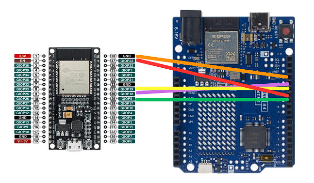
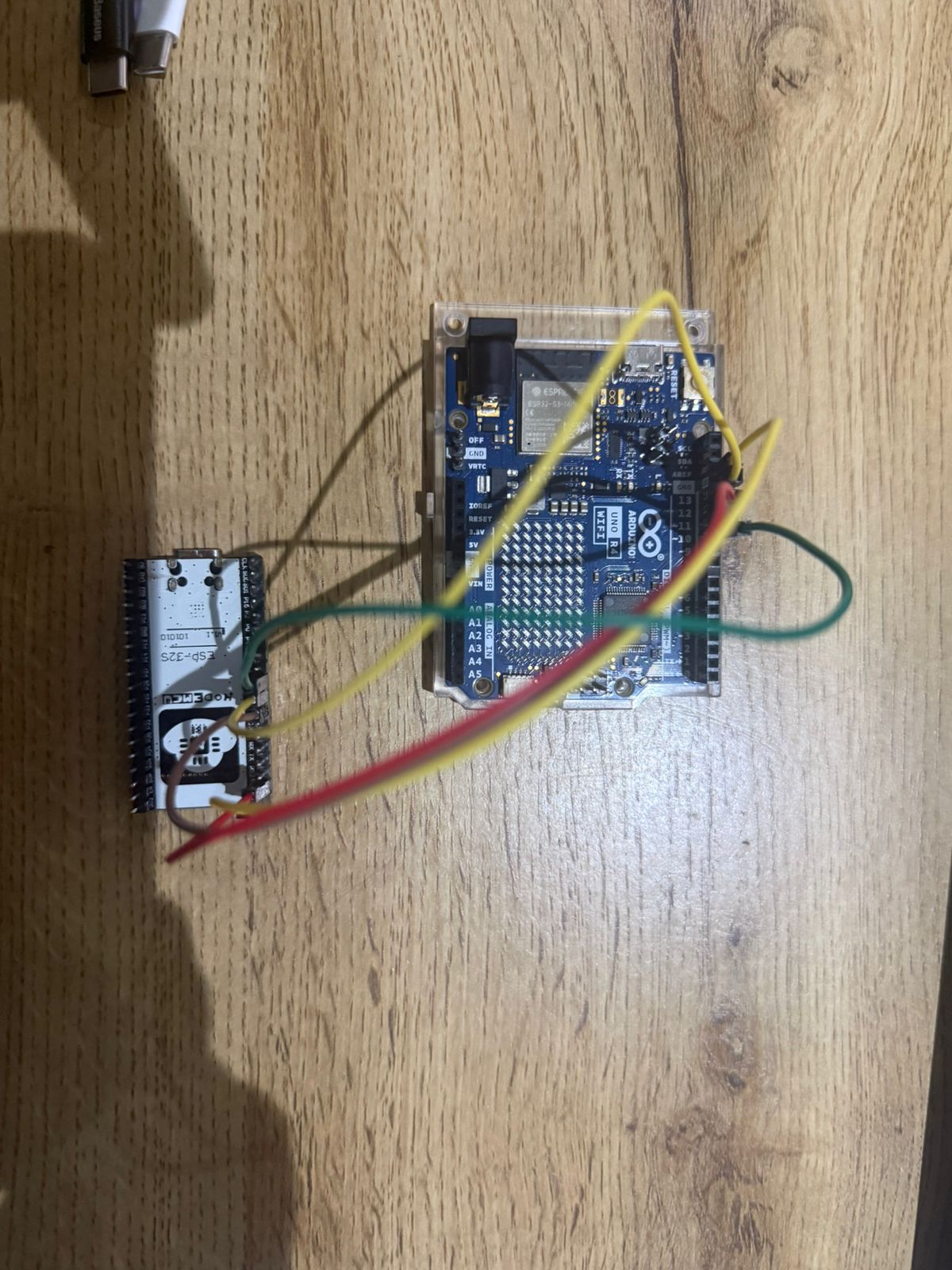
SPI Communication
In this assignment, I implemented SPI (Serial Peripheral Interface) communication between two microcontrollers: the Arduino Uno R4 and the ESP32. The Arduino was configured as the master device, while the ESP32 was set as the slave.
SPI communication is based on four main signals: MOSI (Master Out Slave In), MISO (Master In Slave Out), SCK (Serial Clock), and SS (Slave Select). The master device controls the communication by generating the clock signal and selecting the slave through the SS line. Data is transmitted simultaneously in both directions, enabling full-duplex communication.
During testing, the system was able to establish communication; however, the response was not completely stable. Messages appeared intermittently, likely due to voltage level differences and timing sensitivity in SPI communication.
Pin Configuration
Arduino Uno R4 (Master)
| Function | Pin |
|---|---|
| MOSI | 11 |
| MISO | 12 |
| SCK | 13 |
| SS | 10 |
| GND | GND |
ESP32 (Slave)
| Function | Pin |
|---|---|
| MOSI | GPIO23 |
| MISO | GPIO19 |
| SCK | GPIO18 |
| SS | GPIO5 |
| GND | GND |
SPI Connections
Arduino R4 MOSI (11) → ESP32 GPIO23
Arduino R4 MISO (12) ← ESP32 GPIO19
Arduino R4 SCK  (13) → ESP32 GPIO18
Arduino R4 SS   (10) → ESP32 GPIO5
Arduino R4 GND       → ESP32 GND
Important Considerations
- The Arduino Uno R4 operates at 5V logic, while the ESP32 uses 3.3V logic, which may cause unstable communication.
- SPI communication is sensitive to timing and signal integrity, so short wires are recommended.
- The SS (Slave Select) pin must be controlled properly by the master.

Conclusion
This implementation demonstrates the basic operation of SPI communication, including synchronous data transfer and master-slave control. Although the communication was not fully stable, the experiment highlights the importance of voltage compatibility and timing when working with high-speed protocols.
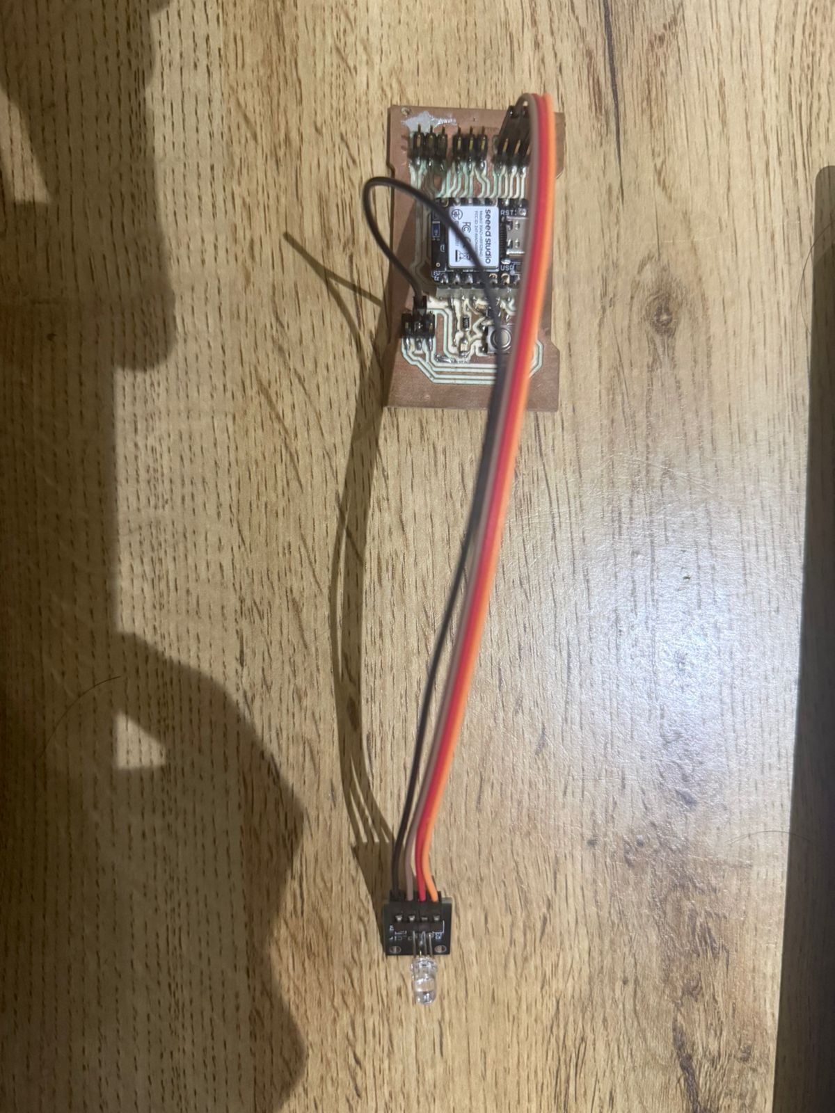
BLE Communication – RGB LED Control
In this test, I used Bluetooth Low Energy (BLE) with the XIAO nRF52840 to control an RGB LED. A BLE service and characteristic were created so that a central device could send values to the board. Depending on the received value, the XIAO turns on the red, green, blue, or all channels of the RGB LED.
XIAO nRF52840 Code (BLE Peripheral)
#include <ArduinoBLE.h>

#define RED_PIN 0
#define GREEN_PIN 1
#define BLUE_PIN 2

BLEService ledService("180C");
BLEByteCharacteristic ledChar("2A56", BLERead | BLEWrite);

void setup() {
  pinMode(RED_PIN, OUTPUT);
  pinMode(GREEN_PIN, OUTPUT);
  pinMode(BLUE_PIN, OUTPUT);

  digitalWrite(RED_PIN, LOW);
  digitalWrite(GREEN_PIN, LOW);
  digitalWrite(BLUE_PIN, LOW);

  BLE.begin();

  BLE.setLocalName("XIAO_RGB");
  BLE.setAdvertisedService(ledService);

  ledService.addCharacteristic(ledChar);
  BLE.addService(ledService);

  ledChar.writeValue(0);
  BLE.advertise();
}

void loop() {
  BLEDevice central = BLE.central();

  if (central) {
    while (central.connected()) {
      if (ledChar.written()) {
        byte value = ledChar.value();

        if (value == 0) {
          digitalWrite(RED_PIN, LOW);
          digitalWrite(GREEN_PIN, LOW);
          digitalWrite(BLUE_PIN, LOW);
        }
        else if (value == 1) {
          digitalWrite(RED_PIN, HIGH);
          digitalWrite(GREEN_PIN, LOW);
          digitalWrite(BLUE_PIN, LOW);
        }
        else if (value == 2) {
          digitalWrite(RED_PIN, LOW);
          digitalWrite(GREEN_PIN, HIGH);
          digitalWrite(BLUE_PIN, LOW);
        }
        else if (value == 3) {
          digitalWrite(RED_PIN, LOW);
          digitalWrite(GREEN_PIN, LOW);
          digitalWrite(BLUE_PIN, HIGH);
        }
        else if (value == 4) {
          digitalWrite(RED_PIN, HIGH);
          digitalWrite(GREEN_PIN, HIGH);
          digitalWrite(BLUE_PIN, HIGH);
        }
      }
    }
  }
}
Control Values
0= OFF1= RED2= GREEN3= BLUE4= WHITE