Final Project
The Idea
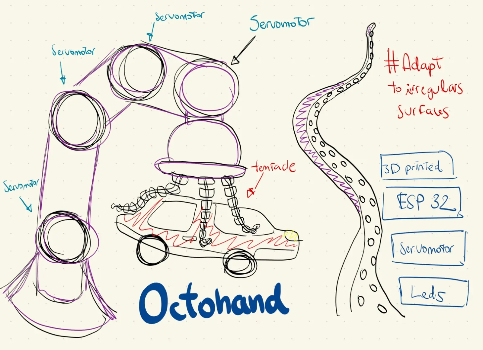
I wanted to build something that challenged the way robotic grippers work. Traditional rigid claws need precise positioning to grab anything, and one wrong move damages whatever they're holding. I kept coming back to the same question: why not build a gripper that adapts to the object instead of forcing the object to fit the gripper?
The answer was octopus tentacles. A real octopus tentacle wraps around anything, regardless of shape, without applying concentrated pressure. The key is flexibility and the way force is distributed across the whole surface. That's exactly what a good gripper should do.
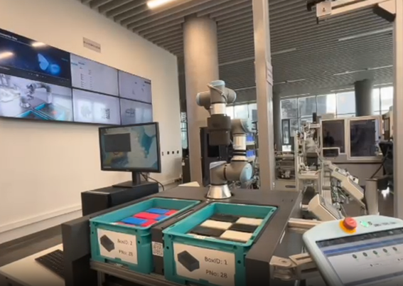
The UR3 at Fab Lab ULima already handles 3D positioning with millimeter precision. What it was missing was a gripper that could handle irregular objects without crushing them. That was the gap — a soft, wireless end-effector controlled entirely by hand gesture over BLE.
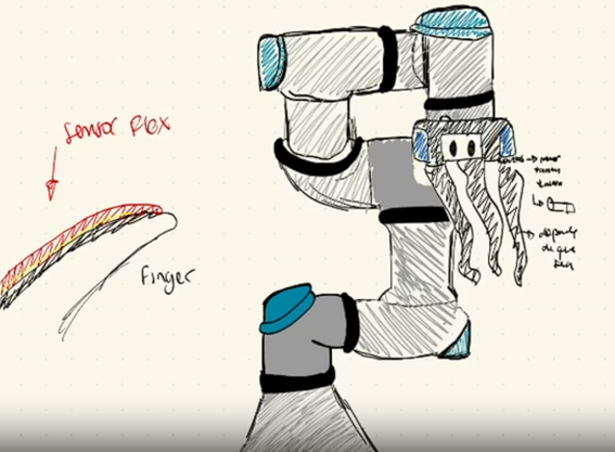
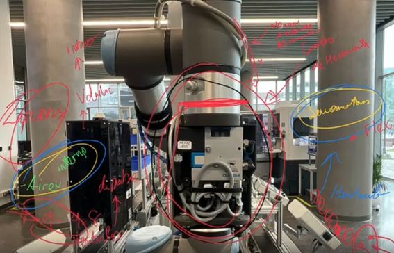
Before designing anything I mapped out the problem directly on the arm, annotating which components were involved and how they would interact: servomotors, flex sensors, internal PCB, microcontroller, cables.
No one had built this kind of system entirely inside a Fab Lab. Every soft gripper I found in research either relied on pneumatic actuators, expensive silicone molding, or proprietary hardware. That was the gap I wanted to close: a fully Fab Lab-fabricated, wireless, wearable-controlled soft gripper for the UR3, under $100 in materials.
System Diagrams
The project is divided into two independent systems that communicate wirelessly via BLE.
Gripper System
Glove System
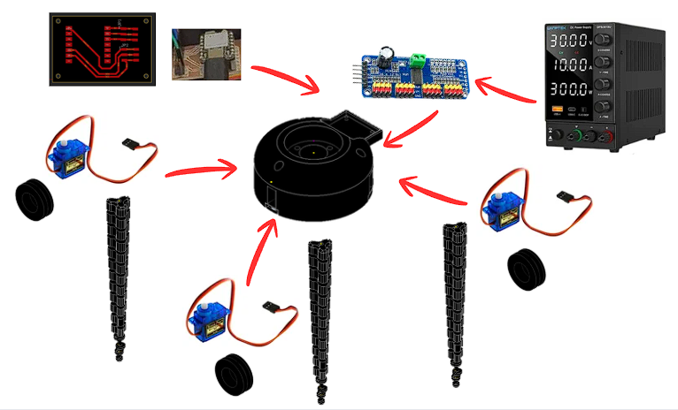
Gripper — Components
- Custom PCB — XIAO ESP32-C6 (BLE RX)
- PCA9685 — 16-ch PWM servo driver (I2C)
- SG90 x3 — micro servo per tentacle
- TPU 95A tentacle x3 — 12 vertebrae + Dyneema
- Hub — 3D-printed servo mount + cable routing
- DC power supply — bench supply for development
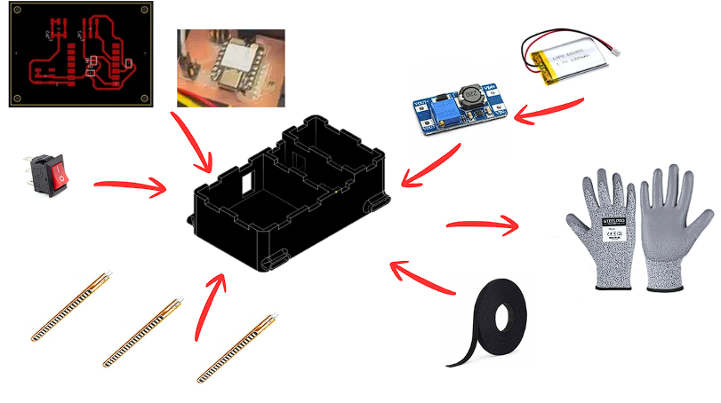
Glove — Components
- Custom PCB — XIAO ESP32-C6 (BLE TX)
- Flex sensors x3 — sewn onto glove fingers
- MT3608 boost converter — 3.7V to 5V step-up
- LiPo 3.7V 1000mAh — battery
- Rocker switch — power on/off
- 3D-printed enclosure — houses PCB + battery
- Velcro tape — attaches enclosure to glove
- Work glove — base for sensor mounting
Signal path — full system
How every subsystem connects, from flex sensors on the glove through BLE to the servo-driven tentacles on the UR3.
Voltage divider
0-3.3 V output
map 0-4095 → 0-120°
BLE GATT TX
JP1-JP3 connectors
LiPo battery
Packet: "A1,A2,A3"
50 ms interval · ~10 m
No cables glove to gripper
Parse "A1,A2,A3"
Gripper PCB board
500-2500 us range
0-120° rotation
Dyneema tendon
Bends to 120°
Custom 3D-printed adapter
Bayonet flange mount
Positions in 3D · gripper operates independently via BLE
Designing the Tentacle
The first real decision was how to make a tentacle that actually bends the way I wanted. I modeled everything in Autodesk Inventor, starting with a single vertebra — a small segment with a hinge-like connection to the next one and a central channel running through the middle for the tendon. Stack twelve of these together and you get a tentacle that bends smoothly from base to tip when you pull the tendon.
The geometry took a while to get right. Too thick and it barely moved; too thin and it collapsed under its own weight. I modeled a tapered profile that gets gradually narrower from base to tip, which distributes the bending stress evenly across all twelve vertebrae — the same way a real cephalopod arm works.
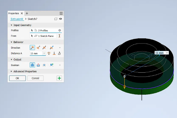
CAD Process — Step by Step
The tentacle was built in Autodesk Inventor across 5 key modeling steps, from the 2D sketch to the full 12-vertebra assembly.
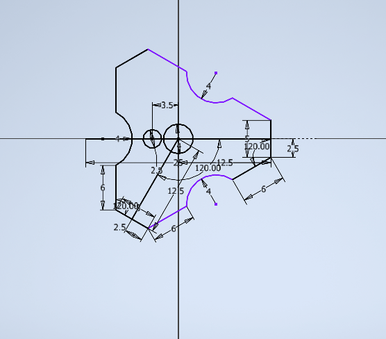
The 2D sketch defines the cross-section of each vertebra. Key dimensions: 3.5 mm wide at the hinge neck, 12.5 mm body width, 6 mm height, 2.5 mm tendon channel diameter. The 120° angles on the side faces allow the vertebrae to lock together at angle without binding when the tentacle bends.
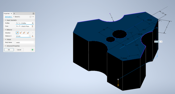
Extrusion 1 takes 3 profiles — the outer body, the tendon channel bore, and the hinge tab geometry — and extrudes them 10 mm to form the solid vertebra block. The three profiles are selected together so all features are cut in one operation, keeping the model clean.
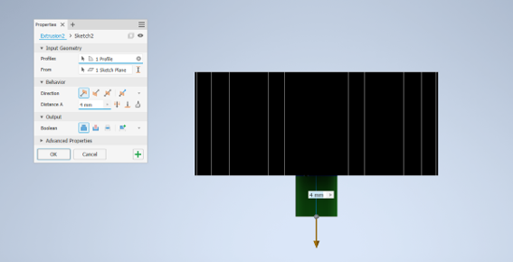
A 4 mm boolean cut removes material to create the flexible neck between vertebrae. This thin section is what allows the TPU to flex at each joint. The 4 mm depth was calibrated so the neck is flexible enough to reach 120° but strong enough to survive hundreds of bend cycles without tearing.
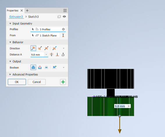
The tendon channel is extended 9.8 mm through the hinge zone using 3 profiles. This ensures the Dyneema line runs continuously from tip to base without kinking at each joint. The 9.8 mm was chosen to align the channel exit exactly at the center of the hinge pivot point.
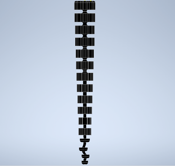
The complete tentacle: 12 vertebrae linked by flexible hinges, with a tapered profile (wider at the base, narrower at the tip) and the Dyneema channel running the full length. At the bottom, the connector base locks into the hub servo pocket; at the top, the tip cap anchors the Dyneema line. Total printed length: approximately 140 mm.
I also designed the central hub that holds the three tentacles radially around the servo mounts, and a custom-printed adapter plate that bolts to the UR3 tool flange.
3D Model — Tentacle viewer
Tentacle Bending Animation
This is how the servo-tendon mechanism works. Drag the slider to pull the Dyneema tendon and watch the tentacle bend.
State: RELAXED
Printing the Tentacles
TPU was the only real option for the tentacles — flexible enough to bend 120° and elastic enough to snap back. I used TPU 95A. The first prints were a disaster: too fast and the layers fused into a stiff block; retraction left strings inside the tendon channel. It took twelve iterations to land on settings that actually worked.
Final TPU print parameters
The gyroid infill at 15% gives the walls just enough internal structure to hold shape without restricting flex. Three perimeters keep the hinge walls strong enough to survive hundreds of cycles. Hub and adapter printed in PLA.
Designing the Hub
The hub is the structural core of the gripper — it houses the three SG90 servos, the gripper PCB, the PCA9685 driver board, and all cable routing, while also interfacing mechanically with the UR3 arm. It was designed in Autodesk Inventor across 4 key extrusions.
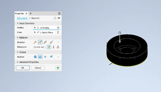
The first extrusion defines the outer geometry of the hub using 14 profiles simultaneously — the circular base plate, three servo pockets at 120° from each other, three tentacle slot openings, and the bolt pattern that matches the UR3 tool flange dimensions. 14 profiles in one operation keeps the feature tree clean. The 25 mm height gives enough structural depth to hold the servos rigidly without the tentacles pulling them loose under load.
This extrusion adds the inner concentric ring that creates the PCB mounting shelf and the servo wire routing channel between the inner and outer walls. The 15 mm height positions the shelf at the right depth so the gripper PCB sits flush with the top of the hub. The two circular profiles define the inner bore where the PCB and PCA9685 sit, and the servo cavity wall that keeps the wiring separated from the servo horn rotation path.
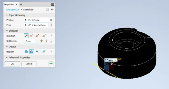
A 17 mm rectangular boolean cut on the side of the hub creates the cable management channel. This slot is positioned exactly where the LiPo power cable and the BLE antenna of the XIAO ESP32-C6 exit the hub body. Routing the cable through a dedicated slot — rather than letting it hang loose — keeps it away from the servo horns rotating inside and makes the assembly look clean from the outside.
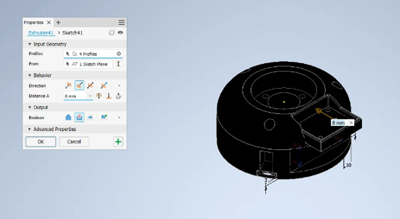
The final extrusion adds the retention geometry for the electronics stack: 4 profiles define the PCB clip tab that holds the gripper board in place, the PCA9685 mounting recess below it, and the three leg posts at the base (3 mm and 10 mm features visible in the dimension callouts) that lock the entire hub assembly onto the custom UR3 adapter. The 8 mm height is the exact clearance needed to stack the XIAO ESP32-C6 on top of the PCA9685 with the I2C header connected between them.
Hub — print parameters (PLA)
3D Model — Hub viewer
Designing and Making the PCBs
The system needs two independent boards that never share a cable: one on the glove (transmitter) and one inside the gripper (receiver). I designed both in Fusion 360 Electronics and milled them on the Roland MDX-50 using FR1 single-sided copper board.
Schematic Design
Each board was first drawn as a schematic in Fusion 360 Electronics before routing the PCB layout. The gripper board connects the XIAO ESP32-C6 to two JST headers (JP1, JP2) that carry 5V, GND, ANALOG, SDA and SCL signals to the PCA9685. The glove board connects the XIAO ESP32-C6 to three JST headers (JP1, JP2, JP3) for the flex sensors, with SMD resistors forming the voltage dividers on each analog channel.
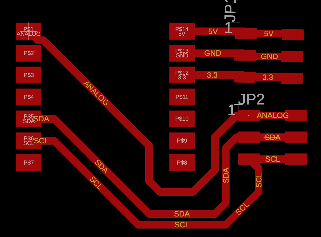
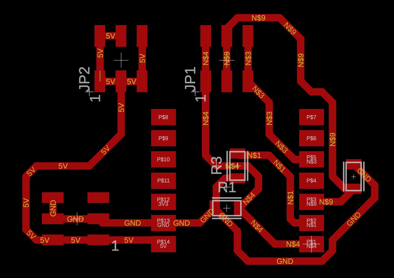
Gripper board PCB layout — XIAO ESP32-C6 RX with JP1 and JP2 connectors routing 5V, GND, ANALOG, SDA and SCL to the PCA9685 servo driver.
Gripper board schematic — XIAO ESP32-C6 with voltage divider resistors R1, R2, R3 and three JST connectors JP1, JP2, JP3 for the flex sensors.
Glove board PCB layout — XIAO ESP32-C6 TX with JP1 and JP2 headers carrying 5V, GND, 3.3V, ANALOG, SDA and SCL signals.
Glove board schematic — XIAO ESP32-C6 with JP1 (5V, GND, 3.3V) and JP2 (ANALOG, SDA, SCL) connectors. The ANALOG pin reads the flex sensor voltage divider output.
Milling — Roland MDX-50
Both boards were milled on the Roland MDX-50 at Fab Lab ULima on FR1 single-sided copper stock. The same workflow and toolpath settings from Week 8 documentation were used.
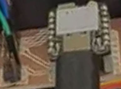
Glove board (TX) during milling on the Roland MDX-50.
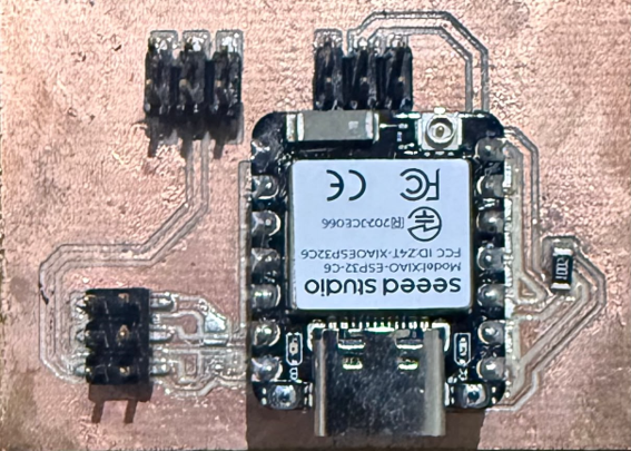
Gripper board (RX) during milling on the Roland MDX-50.
Soldering
SMD soldering with solder paste
The SMD resistors were placed using solder paste applied through a stencil, positioned with tweezers, and cured with a heat gun. The XIAO ESP32-C6 and JST connectors were then hand-soldered. Cleaner and more reliable than hand soldering the resistors directly at that scale.
| Component | Type | Qty | Note |
|---|---|---|---|
| 10 kΩ Resistor | SMD 0805 | 3 | Voltage divider for each flex sensor channel (A0, A1, A2) |
| Pin Header 3×2 | SMD 3×2 | 3 | Connectors JP1, JP2, JP3 — one per flex sensor |
| Pin Header 7×1 | SMD · White | 2 | XIAO ESP32-C6 footprint — left and right side rails |
| Component | Type | Qty | Note |
|---|---|---|---|
| Pin Header 7×1 | SMD · White | 2 | XIAO ESP32-C6 footprint — left and right side rails |
| Pin Header 2×3 | SMD · 2×3 | 2 | JP1 and JP2 connectors — I2C + power lines to PCA9685 |
Building the Glove
Three flex sensors are sewn onto a work glove at the proximal joints of the index, middle, and ring fingers. Each sensor changes resistance from 10 kΩ (flat) to 40 kΩ (bent). Wired in a voltage divider with a 10 kΩ pull-down, the output sweeps 0–3.3 V into the ESP32-C6's 12-bit ADC, giving 4096 steps of resolution per finger.
The glove PCB, LiPo 1000 mAh battery, and MT3608 boost converter are all housed inside a 3D-printed enclosure that attaches to the back of the glove with velcro tape. A rocker switch on the side handles power. No external cables — the entire transmitter is worn.
Writing the Firmware
Both boards run on Arduino. The glove reads the three ADC channels every 50 ms, maps the raw values to 0-120°, and packs them into a single BLE GATT notification — a short string like "45,90,30". The gripper board receives that packet, parses three values, and writes them to the PCA9685 which drives each SG90 servo via PWM at 50 Hz.
I chose BLE because the gripper needs to operate wirelessly while the UR3 arm moves through its full range. The XIAO ESP32-C6 on BLE mode draws around 3 mA. In testing, zero packets dropped at 3 m and only 2 in 500 at 8 m.
Code — Glove (TX) - Click the button
Code — Gripper (RX) - Click the button
BLE Packet Live Demo
This is exactly what happens every 50 ms between the two boards. Move the sliders to bend each finger and watch the packet travel wirelessly to the gripper.
F2:--°
F3:--°
T2:--°
T3:--°
Assembly and UR3 Integration
Assembling the gripper meant threading the Dyneema tendon through each tentacle's central channel and tying it to the servo horn. The tension at assembly matters a lot, too loose and the tentacle barely moves; too tight and the servo stalls. Getting this consistent across three tentacles took time, and it's still the part of the build I'd redesign first.
The gripper PCB and PCA9685 sit inside the hub cavity. The three SG90 servos are press-fit into their radial pockets, the tentacles slot into the base and are locked with a small set screw, and the whole assembly snaps onto the UR3 via the 3D-printed adapter. From there the arm handles 3D positioning while the BLE system manages grasping completely independently.
Wireless Communication
Demonstration of BLE communication between the glove and the Octopus Arm.
Testing and Results
I ran the gripper through a series of pick-and-place tasks with objects of different shapes and materials. A plastic bottle, a foam block, a cardboard box, a soft fabric ball, the tentacles wrapped around all of them correctly, but grip force was not strong enough to hold objects consistently during lifting. The glove interface was immediately intuitive: five people who had never seen it before put it on and controlled the gripper with no instruction within 60 seconds.
BLE stable and low-latency. Tentacles flex and recover after hundreds of cycles with no delamination. Glove interface immediately intuitive. Both PCBs functional on first assembly. PCA9685 gives precise and smooth servo control.
Grip force insufficient across all tested materials — objects wrapped correctly but dropped during lifting. The root cause is tentacle length: the longer the tentacle, the more mechanical advantage is lost at the tip, leaving too little force to hold the load. Shortening the tentacles and repositioning the tendon anchor point is the primary fix for the next version. MT3608 boost converter also runs warm under full servo load.
Open questions for future versions
- Would reducing tentacle length or repositioning the tendon anchor point increase grip force enough to hold objects reliably during lifting?
- Would TPU 85A give better grip compliance while maintaining recovery?
- Can a small cam mechanism replace hand-tensioning to make tendon setup repeatable?
- Would silicone friction pads at the fingertips improve grip on smooth surfaces?
- Is there a cleaner way to route Dyneema through curved channels using PTFE tubing inserts?
Demo Video
Materials and Cost
Total cost: ~$95 USD. Every structural part fabricated at Fab Lab ULima, nothing bought pre-assembled.
| # | Component | Qty | Unit | Total | Source |
|---|---|---|---|---|---|
| 1 | XIAO ESP32-C6 | 2 | $8.00 | $16.00 | Seeed Studio |
| 2 | SG90 Micro Servo | 3 | $2.50 | $7.50 | Local |
| 3 | Flex Sensor 2.2" | 3 | $5.00 | $15.00 | Mercado Libre |
| 4 | PCA9685 16-ch PWM servo driver | 1 | $3.50 | $3.50 | Local / AliExpress |
| 5 | MT3608 boost converter (3.7V to 5V) | 1 | $1.50 | $1.50 | Local / AliExpress |
| 6 | LiPo 3.7V 1000mAh | 1 | $6.00 | $6.00 | Mercado Libre |
| 7 | Rocker switch | 1 | $0.80 | $0.80 | Local electronics |
| 8 | Work glove (base) | 1 | $4.00 | $4.00 | Hardware store |
| 9 | Velcro tape | 1 roll | $2.00 | $2.00 | Hardware store |
| 10 | TPU 95A Filament | ~200 g | — | $8.00 | Local 3D store |
| 11 | PLA Filament (hub, enclosure, adapter) | ~150 g | — | $4.00 | Fab Lab ULima |
| 12 | FR1 Copper Board | 2 | $3.00 | $6.00 | Fab Lab ULima |
| 13 | SMD Resistors 10kOhm (0805) | 1 pack | $1.50 | $1.50 | Local electronics |
| 14 | Dyneema tendon line | 3 m | — | $4.00 | Fishing store |
| 15 | Low-friction PTFE tubing | 30 cm | — | $2.00 | Local |
| 16 | Pin headers / terminal blocks | assorted | — | $3.00 | Fab Lab stock |
| 17 | M4 screws, wire, misc | — | — | $3.70 | Local hardware |
| TOTAL | ~$95 USD | USD | |||
What's Next?
The Octopus Gripper works, but there's a lot left to explore.
Design a small cam mechanism inside the hub so tendon pre-tension is set the same way every time, no more guessing at assembly.
Add force-sensitive resistors at the tentacle tips so the system can detect when something is actually being held and alert the user.
Scale from 3 to 5 or 6 tentacles for better coverage around irregular objects. The hub design is already modular so this is just a new print.
Package everything as a lab kit for university robotics courses — pre-milled PCB, printed parts, Dyneema, servos, and a printed guide. Build it in one session.
Downloads
Everything is published openly under CC BY-NC-SA 4.0 — use it, modify it, build on it, just give credit and keep it non-commercial.
Weekly Documentation
System Integration — Week 15
Full system diagram, BLE firmware, interactive node map. View Week 15
Dissemination Plan — Week 18
License, future development, and open-source distribution plan. View Week 18
All assignments
Full weekly documentation from week 1 to 19. View assignments