Group Assignment
## Group Assignment - Send a message between two projects - Document your work to the group work page and reflect on your individual page what you learned Full details on our **[Lab Group Page](https://fabacademy.org/2026/labs/techworks/week11/week11.html)**.
## Information Architecture For this weeks assignment I decided to create a mockup of the communication between my final project Digital Contour Guage and my laptop. The idea is to test and learn how to build the communication such that the inputs of the digital contour guage are transmitted in DXF file formats. But first I explored the network topologies to learn more about them ### The Basics We were first introduced to the basics, from chip scale whispering to communication global wise, starting with inner circles; the communication between inner chips connected to different ports,which scales to communicating with devices where we can choose different protocols and methadologies. Between those protocols is usually a computer,we can program the computers in different ways,eventually they will work together forming a network. A network can centralized or decentralized. ### The OSI communications model The OSI communication model is the standard of how computer systems and networks commuincate by breaking the complex processes into seven distinc layers ,the layers start from user-facing (those layers interact with software and the human operator,managing data formats,user interface and application logic) to hardware facing (those layers interact with physical equipment and cables,moving electrical signals,waves and bits across physical hardware) We focused mainly on the physical layer and then communicating that. ### Architecture Summary Table | Communication Type | Protocol / Technology | Shared Bus? | How Devices are Addressed | Physical Wiring / Setup | Best Used For... | | :--- | :--- | :--- | :--- | :--- | :--- | | **Wired** (Short Range) | **UART** (Serial) | **No** (Point-to-point) | No addressing needed (only 2 devices total). | 2 wires ($TX \rightarrow RX$, $RX \rightarrow TX$) + shared Ground. | Debugging, direct microcontroller-to-computer links. | | **Wired** (Short Range) | **I2C** | **Yes** | **Software Addressing:** Every device has a hardcoded 7-bit binary address. | 2 wires (SDA for Data, SCL for Clock) + Pull-up resistors. | Connecting multiple low-speed sensors/screens to few pins. | | **Wired** (Short Range) | **SPI** | **Yes** (Data/Clock lines) | **Hardware Addressing:** A dedicated "Chip Select" (CS) wire for each device. | 3 shared wires (MOSI, MISO, SCK) + 1 unique CS wire per device. | High-speed data transfer (SD cards, high-res displays). | | **Wireless** (Personal) | **BLE / NFC / RFID** | **Yes** (Shared airwaves) | Unique MAC addresses or hardware UID tags. | Wireless (2.4GHz for BLE; Electromagnetic fields for RFID/NFC). | Smartphone pairing, wearable sensors, tap-to-pay tags. | | **Wireless** (Local) | **Wi-Fi** | **Yes** (Shared airwaves) | IP Addresses assigned by a central router/Access Point. | Wireless (2.4GHz / 5GHz frequencies). | Connecting a local project to the internet (heavy data). | | **Wireless** (Long Range) | **LoRa** | **Yes** (Shared airwaves) | Network session IDs and device addresses (DevAddr). | Wireless (Sub-GHz frequencies like 868MHz or 915MHz). | Sending small data packets over kilometers on a battery. | ### Key Takeaways for "Bus" Architectures: * **Wired buses (I2C/SPI)** save hardware real estate by letting multiple chips "talk" over the same copper paths on a circuit board. * **Wireless networks** essentially treat the open air as a massive, invisible shared bus—which is why they require strict protocols (like Wi-Fi channels or BLE handshakes) to keep data from colliding. ## Protocol Deep-Dive I evaluated the trade-offs between **Asynchronous** and **Synchronous** communications. | Feature | UART (Serial) | I2C | SPI | | :--- | :--- | :--- | :--- | | **Type** | Asynchronous | Synchronous | Synchronous | | **Wires** | 2 (TX, RX) | 2 (SDA, SCL) | 4 (MOSI, MISO, SCK, CS) | | **Addressing** | Point-to-Point | 7-bit Software Address | Chip Select (Physical Pin) | **Synchronous Protocols (I2C/SPI)** are superior in high-noise environments because the shared clock ensures the receiver reads bits exactly when the transmitter pulses them.

## Individual Assignment ### Workflow I first prototyped the circuit using a breadboard ,given my PCB was damaged , I kind of had to. Here is a visual summary of the bread board connections. I then proceeded to reflect this on a new PCB I created, adding to my final project to transmit the scans on a remote hand held device (watch like). The full documentation of the PCB design and production can be found [here](week-11-pcb.html) You can find the code break down structure for the arduino side and python side at the bottom of the page under references and source files sections.
Breadboard Setup

Digital Contour Guage Mockup - Breadboard

Digital Contour Guage Mockup - Computer Side

### Communication Flow 1. The potentiometers control two points on the OLED. 2. The push button captures the positions 3. Long pressing the push button opens up a gallery 4. You can scroll through the gallery, and again longpress to send to PC. ### Programming Process / Software Logic #### Arduino IDE I used Arduino IDE to program the RP2040, in specific I focused again on using the **map()** function which handled the scaling of the analoge range (0-1023) to fit the OLED screen 0-127 pixels , **map(raw X, 0, 1023, 0, 127);** as an **inner circle** function which displayed the profile generated between the two points from the potentiometer using the synchronous I2C connection , display. **begin**,**drawPixel**, **display**. Finally the code send to the **Network** using **Serial** functions. ### Arduino IDE Network Functions Summary | Library / Protocol | Specific Function Used | What It Physically Does on Your Network | | :--- | :--- | :--- | | **Internal Bus (I2C)**
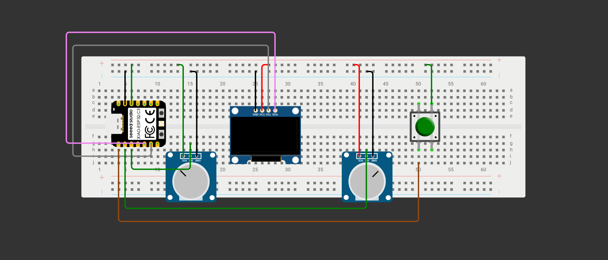
*Local Display Sub-Network* | `Wire.setSDA(6);`
`Wire.setSCL(7);` | Maps the physical data and clock lines to Pins 6 and 7 so the signal goes out the right physical doors. | | | `Wire.begin();` | Wakes up the I2C bus hardware inside the XIAO RP2040 chip to turn it into an active network controller. | | | `display.begin(..., 0x3C);` | Sends a wakeup call targeting the specific **bus address (`0x3C`)** of your local OLED display node. | | | `display.drawPixel(x, y, ...);` | Plots a single coordinate point on the screen grid without clearing your old data lines. | | | `display.display();` | Flushes all the buffered drawing data down the physical wires to instantly render it on the glass. | | **External Link (Serial)**
*Laptop Communication Bridge* | `Serial.begin(115200);` | Opens the communication gate and sets the **Baud Rate** to 115,200 bits per second so the laptop can match speeds. | | | `Serial.print(x);` | Pushes the X-coordinate text out through the USB-C cable bridge. | | | `Serial.print(",");` | Sends a comma right after the X value to act as a **Delimiter** (a clear separator between the numbers). | | | `Serial.println(y);` | Sends the Y value and automatically appends a **Newline (`\n`)** character to act as the packet's **Stop Frame**. |
### Code Flow summary Arduino Reads the Code > Converts it to Electricity through the cables > Scales them to fit the screen >Packs and send them to the laptop #### Python While the XIAO RP2040 handles physical data collection, the laptop functions as the master node. I authored a Python script using the **pyserial** and **ezdxf** libraries to act as an asynchronous listener, string parser, and CAD file generator. ### Setting up the port and Matching Speed Before catching the data, a network configuration must be defined using **serial.Serial(PORT, BAUD)** his initializer opens a direct data bridge to 'COM7' at a speed of 115200 bits per second. Because there is no external clock signal to dictate when to read data (Asynchronous / UART) this software configuration forces the laptop to sample the incoming USB line at precise intervals. So if the BAUD rate does not match arduino configuration , we would have issues. To relate this Here is the arduino portion that defines the baud rate **Serial.begin(115200);** and in the python file ```python # --- Configuration --- PORT = 'COM7' BAUD = 115200 TINE_PITCH = 3.0 # 3mm between tines MAX_TRAVEL = 50.0 # 50mm max extension JSON_FILE = "data.json" LOG_FILE = "scans.json" DATA_DIR = "scans" ``` ### Monitoring and Catching the Byte Packets (The Serial Buffer) Since I am using UART which is **Point-to-point** protocol , it means we're exactly working with two devices to ensure we that the communication is exclusively between the two devices I learned to use, **ser.readline()**, his function instructs Python to continuously pull data from the serial buffer until it runs into a newline character (\n). This relies entirely on standard UART Packet Framing. It acts as the software "Stop Frame," keeping the Python script in a holding pattern until a complete line of text has finished transferring over the wire. It is worth mentioning here I realized the difference between **Master** and **Slave** , in a way the laptop was the master node, and the RP2040 is the slave node, I learned that UART is Peer to Peer however the structure im doing makes the laptop kind of like the master as it processes most of the data coming from the RP2040 ### Cleaning, Decoding, and Protocol Handshaking Once raw electrical signals travel across the physical network link, they must be converted from computer bytes back into structured application variables. This requires matching text triggers on both sides of the network to manage the system state. #### The Arduino Side (Data Initialization) When navigating to the `SEND PC` option on the breadboard menu and triggering it, a dedicated menu execution function runs. The Arduino node initiates a transmission block by firing clear structural keys down the serial line to signal the laptop. **The firmware executes a line print command to send the literal string text `START_DATA` down the line, runs the data transmission loop, and concludes by executing another line print command to send the literal string text `END_DATA` to seal the session.** #### The Python Side (Stream Extraction) On the laptop, the Python script continuously processes the incoming stream using these matching triggers. **The Python script utilizes a read-line instruction to pull bytes from the serial buffer, applies a UTF-8 decoding method to convert binary data into string text, and invokes a strip function to scrub away trailing system whitespace characters.** * **Functionality & UART Relation**: UART ports transfer raw binary voltage pulses. Python captures these as a raw byte string. The decoding function translates these bits back into human-readable text characters, and the strip function finishes the cleaning process by removing the invisible layout characters (`\r` and `\n`) that were automatically attached by the Arduino line-print commands. The script evaluates incoming lines against the handshake keys: it only opens its secondary internal data-collection loop once it intercepts the exact `START_DATA` string from the UART queue, and breaks the loop to finalize file compilation the moment it catches the `END_DATA` string. ### Slicing the Geometric Stream (Data Parsing) Because a point-to-point UART connection pushes data sequentially down a single physical data stream, multiple values must be packaged together with strict markers so the receiving program can distinguish where one number stops and the next begins. #### The Arduino Side (Data Packaging) Inside the array transmission loop, the firmware packages multiple independent variables into structured text sentences. **The firmware uses sequential print commands to output a header string reading `SCAN` followed by a colon, followed by the index number, a comma, the first coordinate pair, another comma, and concludes with a line print command for the final coordinate to attach the stop character.** This dumps a packaged text frame down the cable that reads precisely as follows: ```text SCAN:0,0.0,12.5,3.0,15.2\n ### Distributed Application Layer (Creating the CAD File & Logs) This final step represents distributed processing. The XIAO microcontroller node handles real-time menu button state filtering, mathematical mapping, and memory arrays locally on the breadboard, freeing up the host computer script to handle heavy file compilation and disk-writing operations. #### The Arduino Side (Unit Conversion) **The firmware utilizes a mapping function to mathematically convert the visual pixel coordinates stored in the local library array back into real mechanical coordinates based on a pre-defined maximum travel constant of `50.0 mm`.** * **Functionality & UART Relation**: Before sending metrics over the line, the Arduino translates local visual pixels back into mechanical coordinates. Sending standardized manufacturing units over the network optimizes data efficiency across the communication link. #### The Python Side (Storage Execution) Once the coordinates are derived from the split packets, the Python program manages the file structure architecture. **The Python script invokes the `ezdxf` new drawing function to build a model workspace in system memory, passes the coordinate pairs to an add-line function to draw vector segments, executes a document save command to compile the standalone DXF file, and calls a JSON dump function to write the profile metrics into a historical logging file.** * **Functionality**: This handles the final formatting and storage. It maps the node coordinates directly into line objects within a fresh vector workspace, outputs the network data stream into a standalone `.dxf` format for direct use in programs like Fusion 360, and packages the data into structured JSON objects to build a master index data history on the storage drive without risking file corruption. ### Python Libraries Used | Library | Purpose in the Project | What It Physically / Logically Does | | :--- | :--- | :--- | | `serial` *(pyserial)* | UART communication with the RP2040 | Opens the COM port and continuously listens to the incoming byte stream over the USB serial bridge. | | `json` | Structured data storage | Converts Python dictionaries and arrays into machine-readable `.json` files for scan logging and live data storage. | | `time` | Timestamp generation | Creates formatted timestamps used for filenames, historical indexing, and scan tracking. | | `ezdxf` | CAD geometry generation | Converts coordinate pairs into DXF vector line entities and exports standalone CAD files. | | `os` | File and directory management | Creates folders, checks file existence, renames files, and manages storage architecture on the computer. |


## Troubleshooting & Problem Solving ### Problem 1: Establishing Communication Between the RP2040 and Laptop * **Challenge:** At the beginning of development, I was unsure how to create the communication bridge between the XIAO RP2040 and the laptop. I explored different approaches such as direct serial communication, Python-based listeners, and alternative networking methods. * **What I Learned:** I eventually learned that the simplest and most stable solution for this architecture was using **UART Serial Communication** over the USB-C cable. The RP2040 transmits structured text packets using Arduino `Serial.print()` functions, while a Python script on the laptop continuously listens to the COM port using the `pyserial` library. * **Final Solution:** The system architecture became: * **RP2040** → Handles sensing, mapping, and packet generation. * **UART / USB Bridge** → Transfers byte streams. * **Python Listener** → Decodes and processes the incoming packets. * **DXF / JSON Generator** → Stores the reconstructed geometry data. --- ### Problem 2: Serial Port Conflict Between Arduino IDE and Python * **Challenge:** One major issue was that the Arduino IDE and the Python script could not access the serial port simultaneously. Whenever the Python script was running, uploading firmware from Arduino IDE failed because the COM port was already occupied. * **Technical Cause:** UART serial ports are point-to-point communication channels. Only one software process can "own" the COM port at a time. If Python opens the port first using `serial.Serial(COM7, 115200)`, the Arduino IDE bootloader cannot access it. * **Final Solution:** I learned that I had to completely close the Python listener before uploading firmware. Likewise, after uploading finished, the Arduino Serial Monitor had to remain closed before relaunching the Python script. * **Key Takeaway:** Serial communication behaves like an exclusive hardware tunnel. The operating system locks the port to whichever application opens it first. --- ### Problem 3: Generating Valid JSON and DXF Files * **Challenge:** Another major challenge was understanding how to convert incoming UART data into actual engineering file formats that could later be reused inside CAD software. * **DXF Solution:** I discovered the Python **ezdxf** library, which allowed the coordinate packets received from the RP2040 to be reconstructed into vector geometry. The script generates DXF line entities directly from the transmitted coordinate pairs and exports them into standalone CAD files. * **JSON Solution:** For JSON storage, I learned to use Python’s built-in **json** library to serialize structured scan data into `.json` files. After decoding the UART stream, the Python script reconstructs the coordinate pairs into dictionaries and arrays, then uses `json.dump()` to write the scan data into machine-readable JSON architecture. * **Functionality:** The JSON files act as historical scan logs and live application data, while the DXF files store the actual CAD geometry reconstruction. * **Key Takeaway:** The RP2040 only transmits raw coordinate information over UART. The laptop acts as the higher-level processing node responsible for decoding the serial stream, reconstructing the geometry, and converting the incoming data into structured engineering formats such as DXF and JSON.
as

Resources & Assets