Group Assignment
As a group we characterized the design rules for our in-house PCB production. We wrote down the settings our CNC 3018 can reliably make, like the smallest trace width, the clearance between traces and the drill size, and we also documented the workflow for sending a PCB to a board house. The results are on our group page: group assignment page.
Individual Assignment
Testing an embedded microcontroller system you designed
Summary
I exported my circuit design as an SVG and used ModsProject to generate G-code. The code was run in candle on CNC 3018 to mill the PCB. After soldering the components, I tested the circuit by programming the LED and LDR,
Plotting PCB
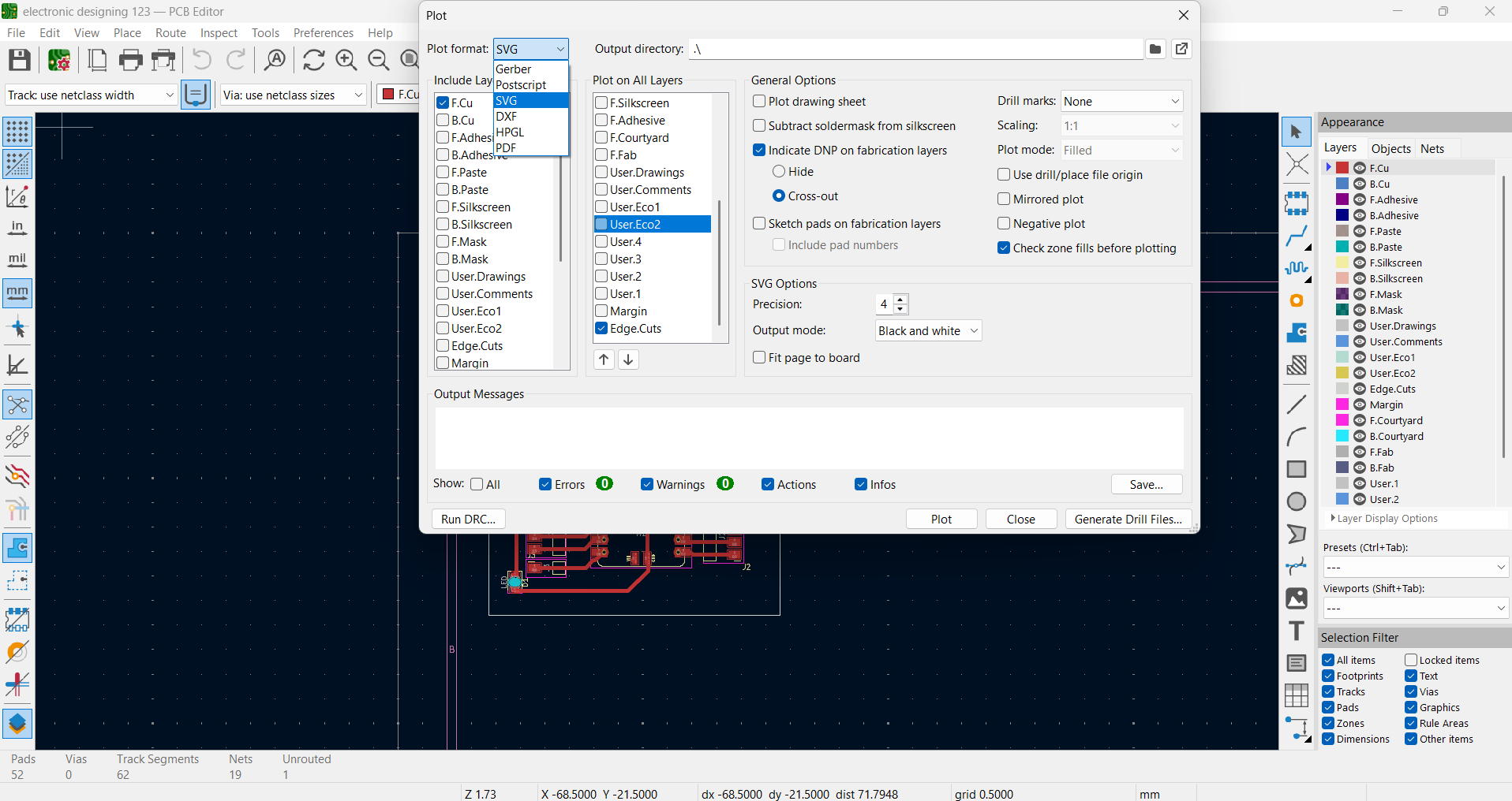
I clicked Plot and chose SVG as the file type. Then I selected the layers I needed Edge Cuts for the board shape and Front Copper for the circuit
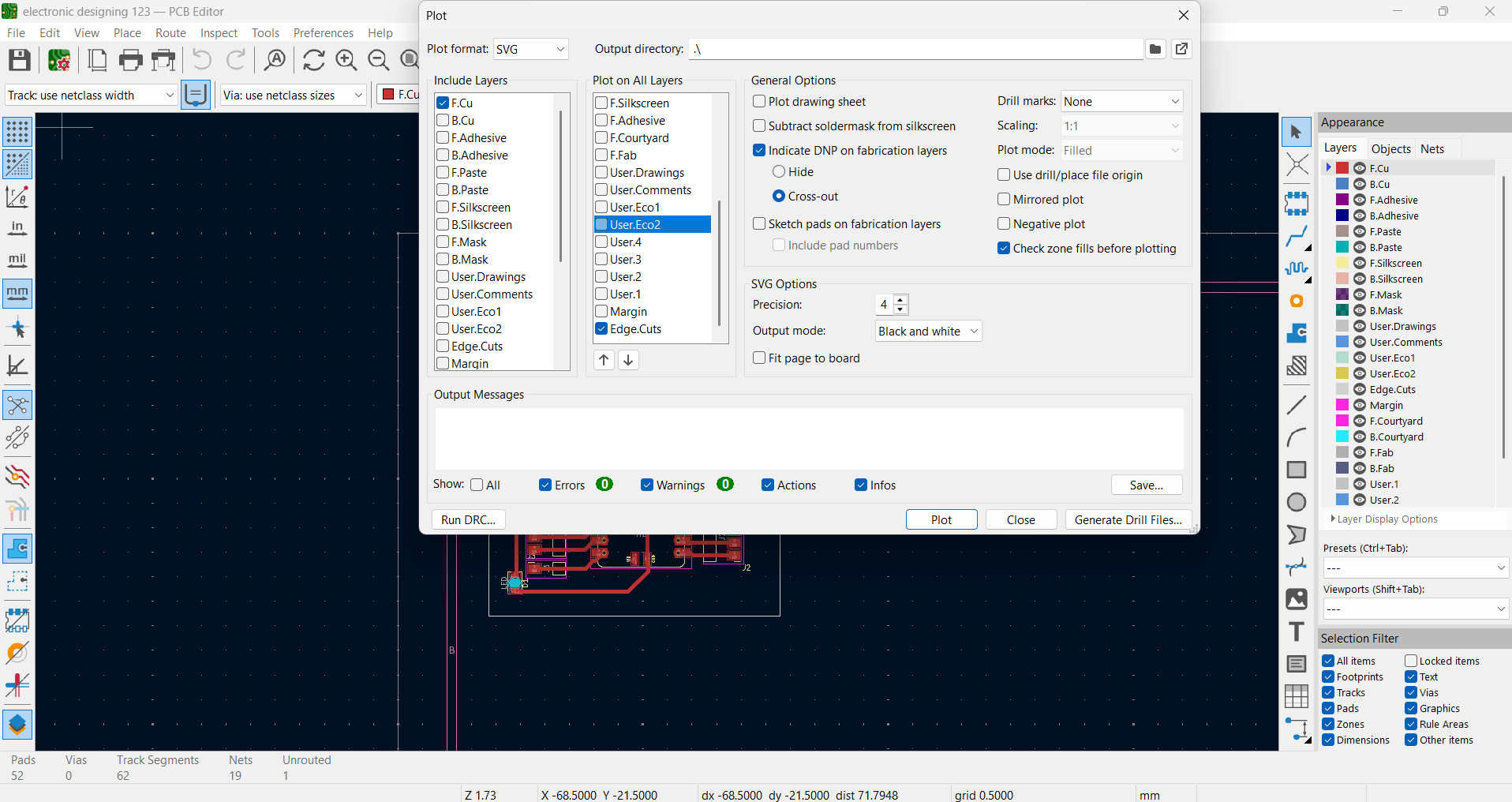
After plotting, I select the files as SVG so they could be used in ModsProject
ModsProject
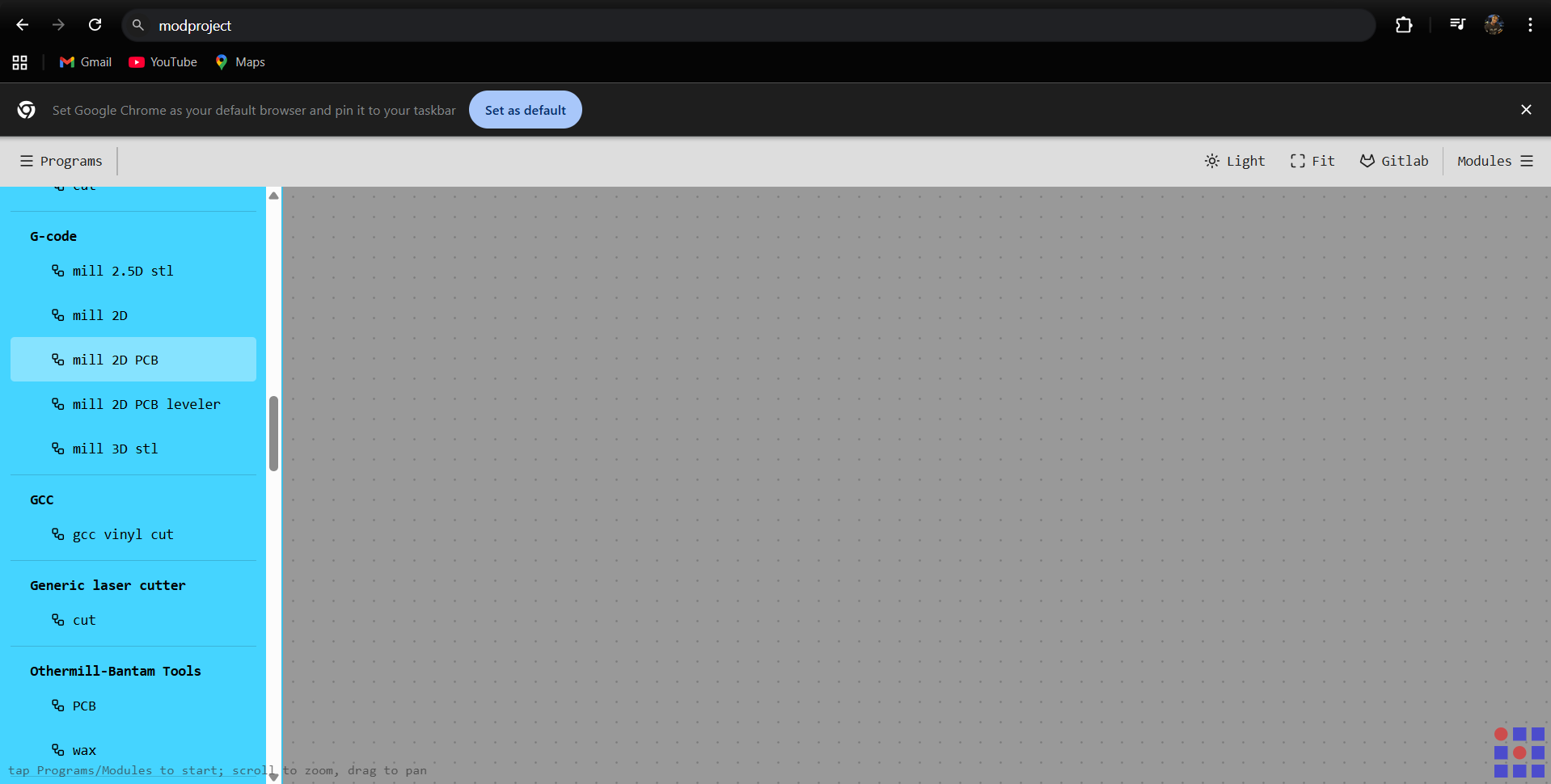
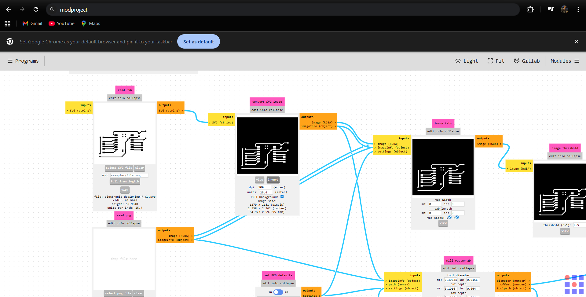
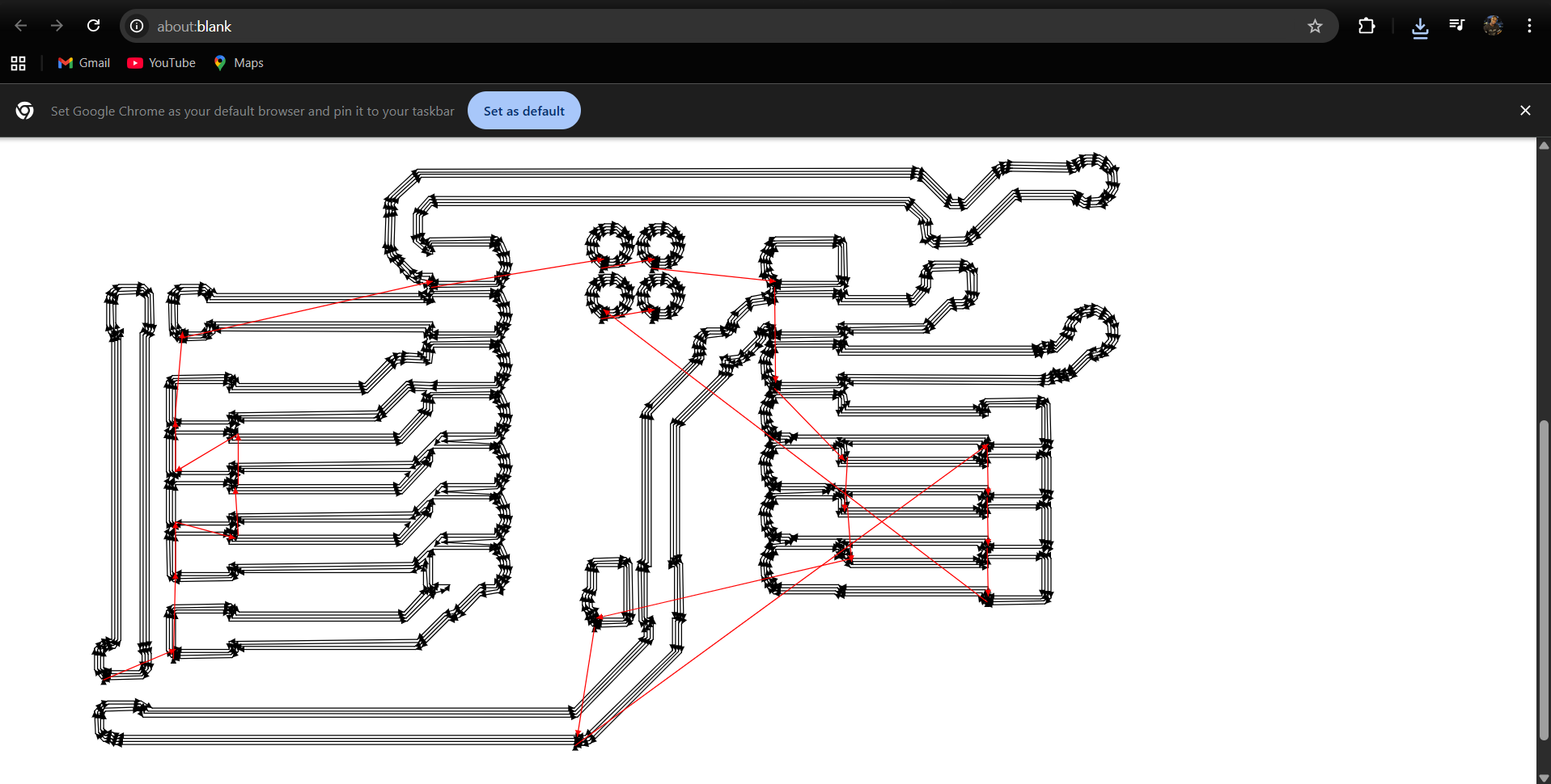
Next, I opened ModsProject, chose GCODE Mill 2D PCB, and imported the SVG file
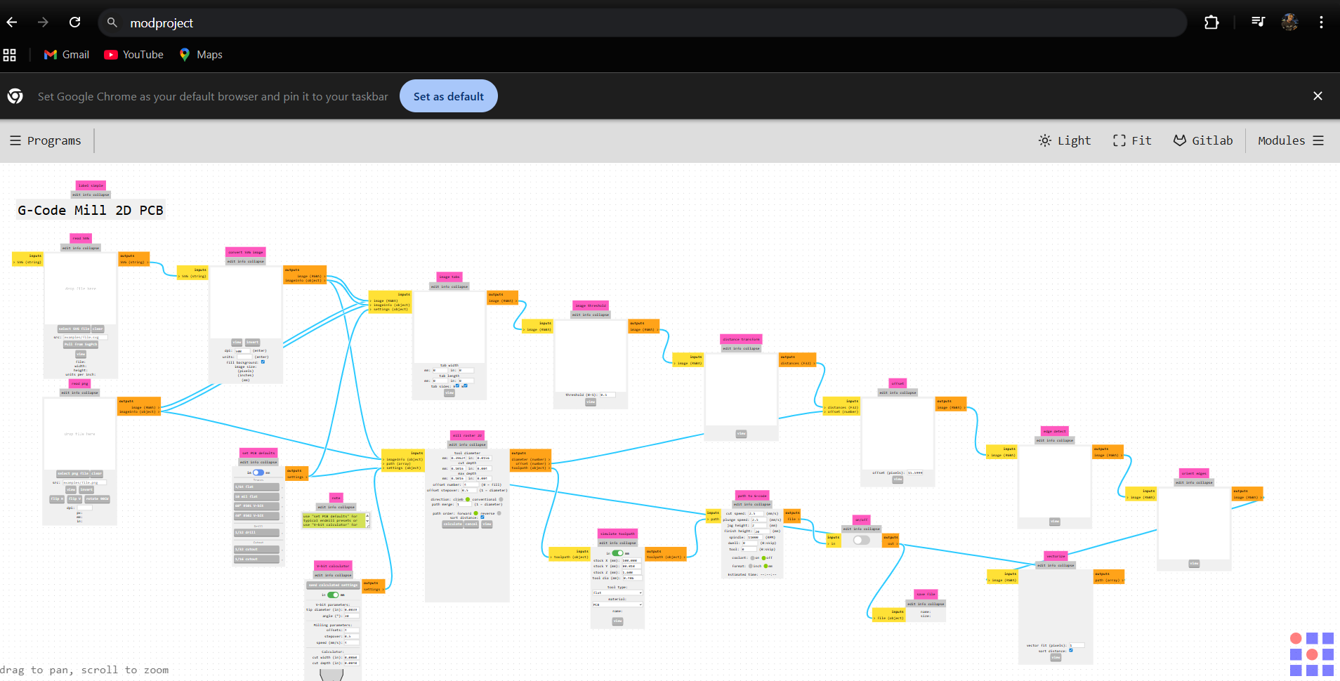
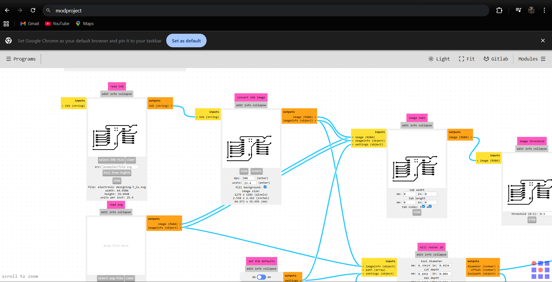
chose invert to set the correct milling area
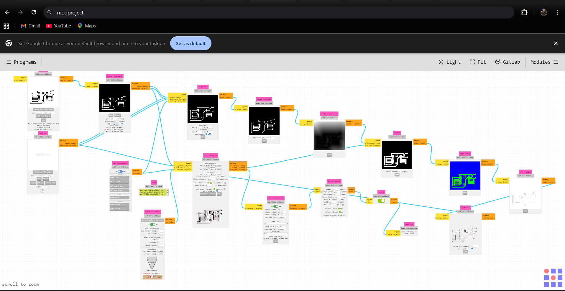
after, I went to Set PCB Defaults and picked Milly Trace. Then, in V-Bit Calculator, I set the tip diameter to 0.3 mm and the offset number to 4. After that, I sent these settings to Mill Raster 2D
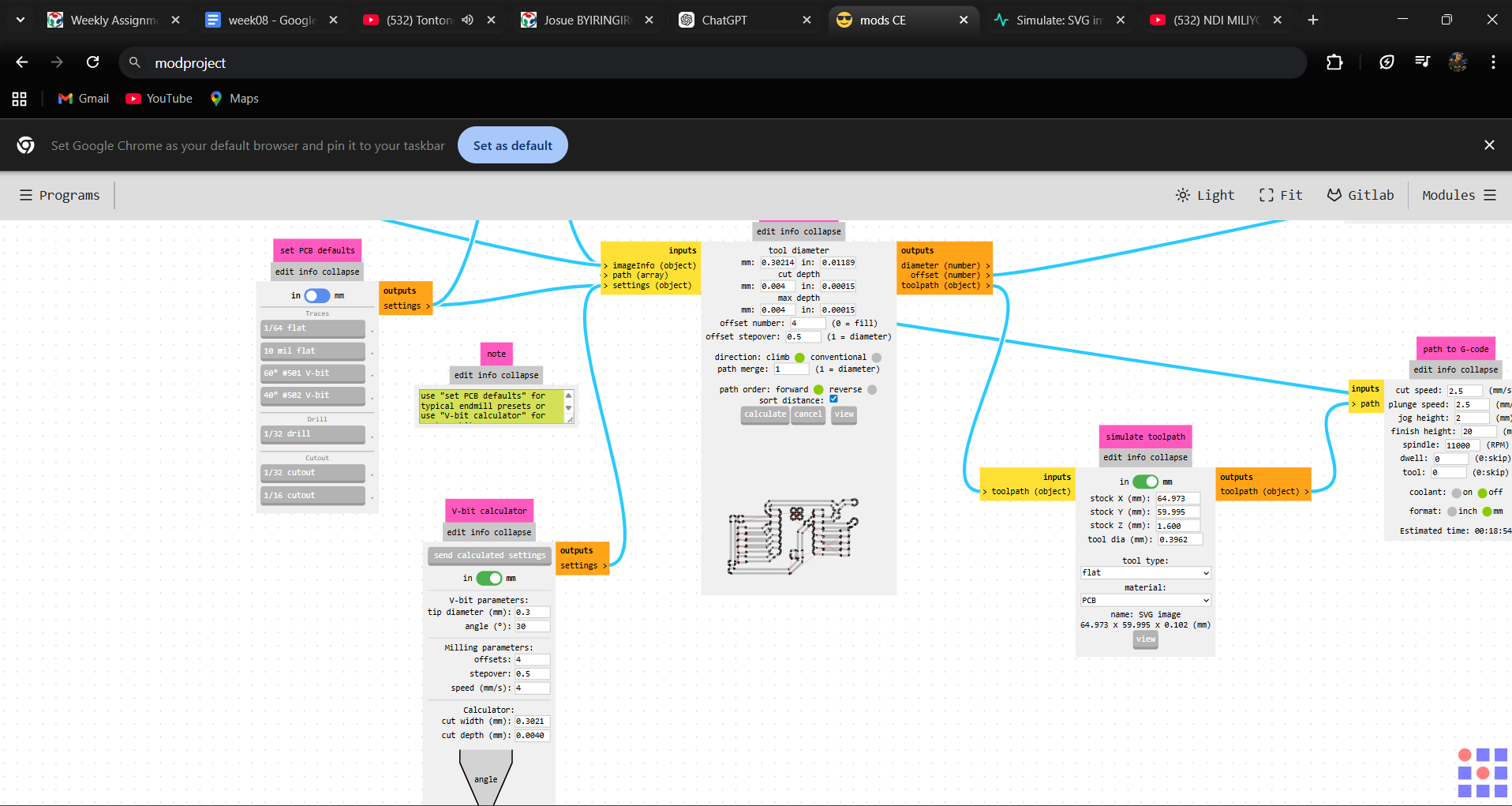
next,I went to the Mill Raster 2D section and clicked Calculate. To generated the G-code, and downloaded
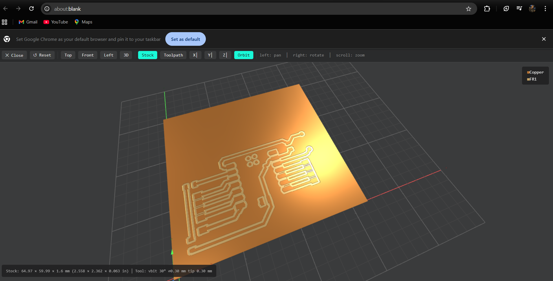
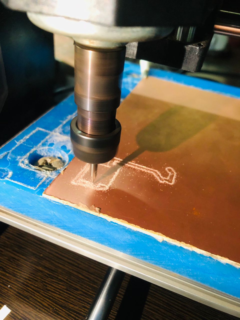
Milling PCB
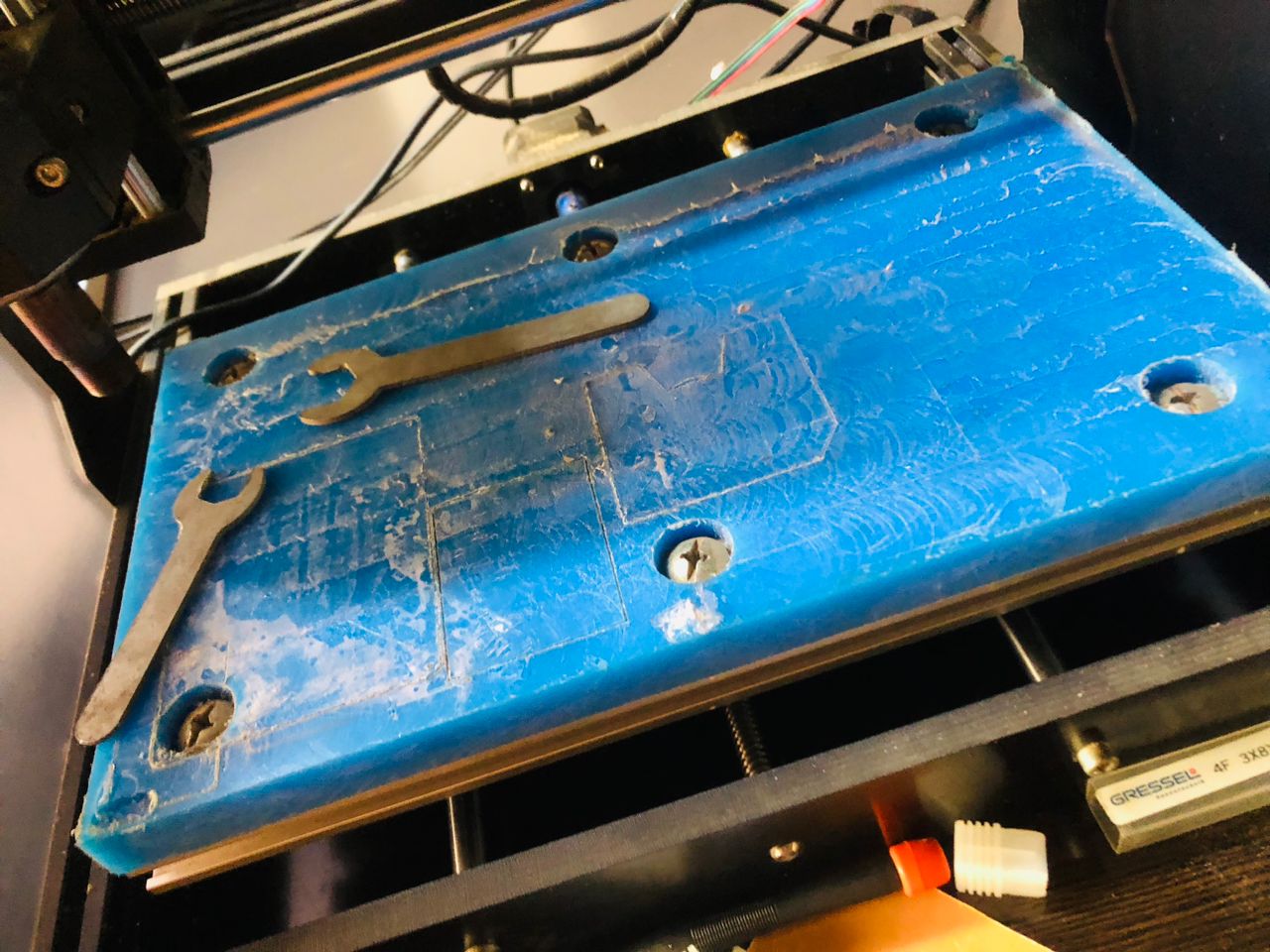
I using a CNC 3018, I opened the candle and loaded the generated G-code. I then fixed the copper board into the CNC bed using double-sided tape.
I added double-sided tape to the copper board and fixed it firmly onto the CNC bed
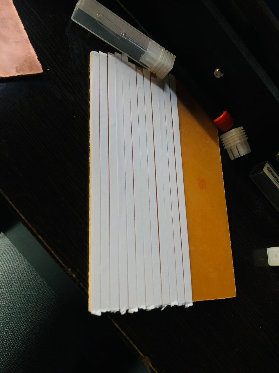
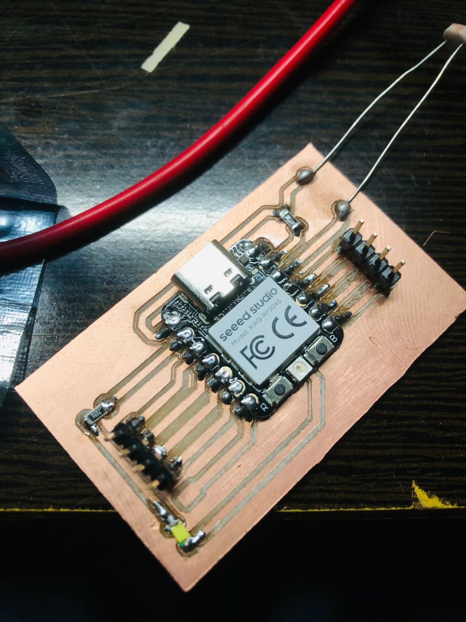
final result of milling
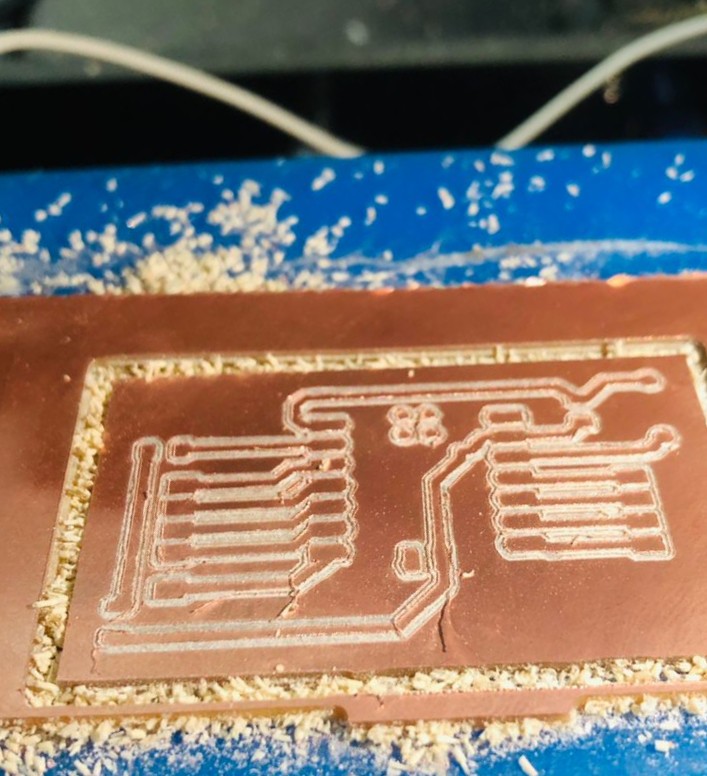
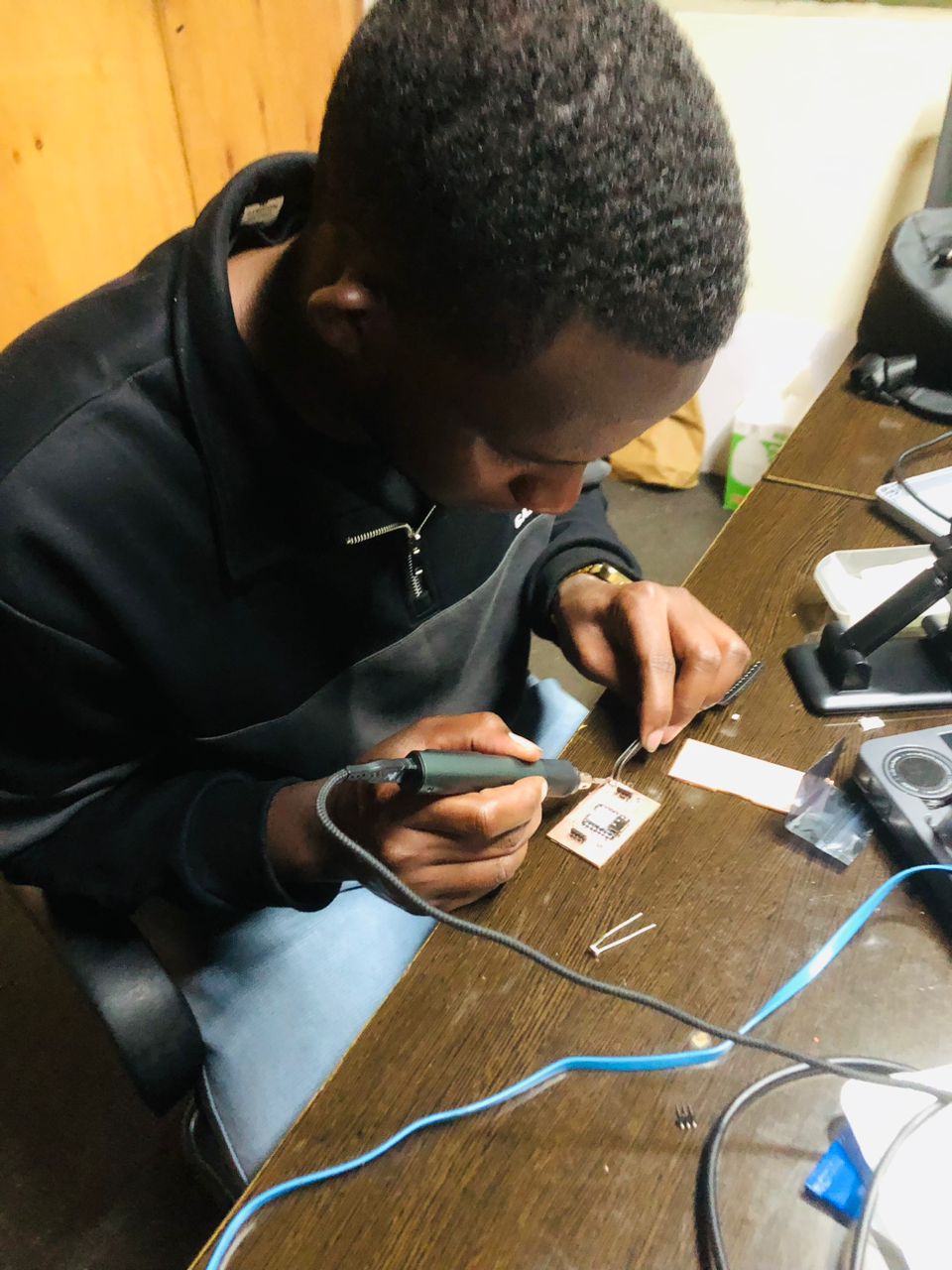
After milling, I soldered the components into the pcb
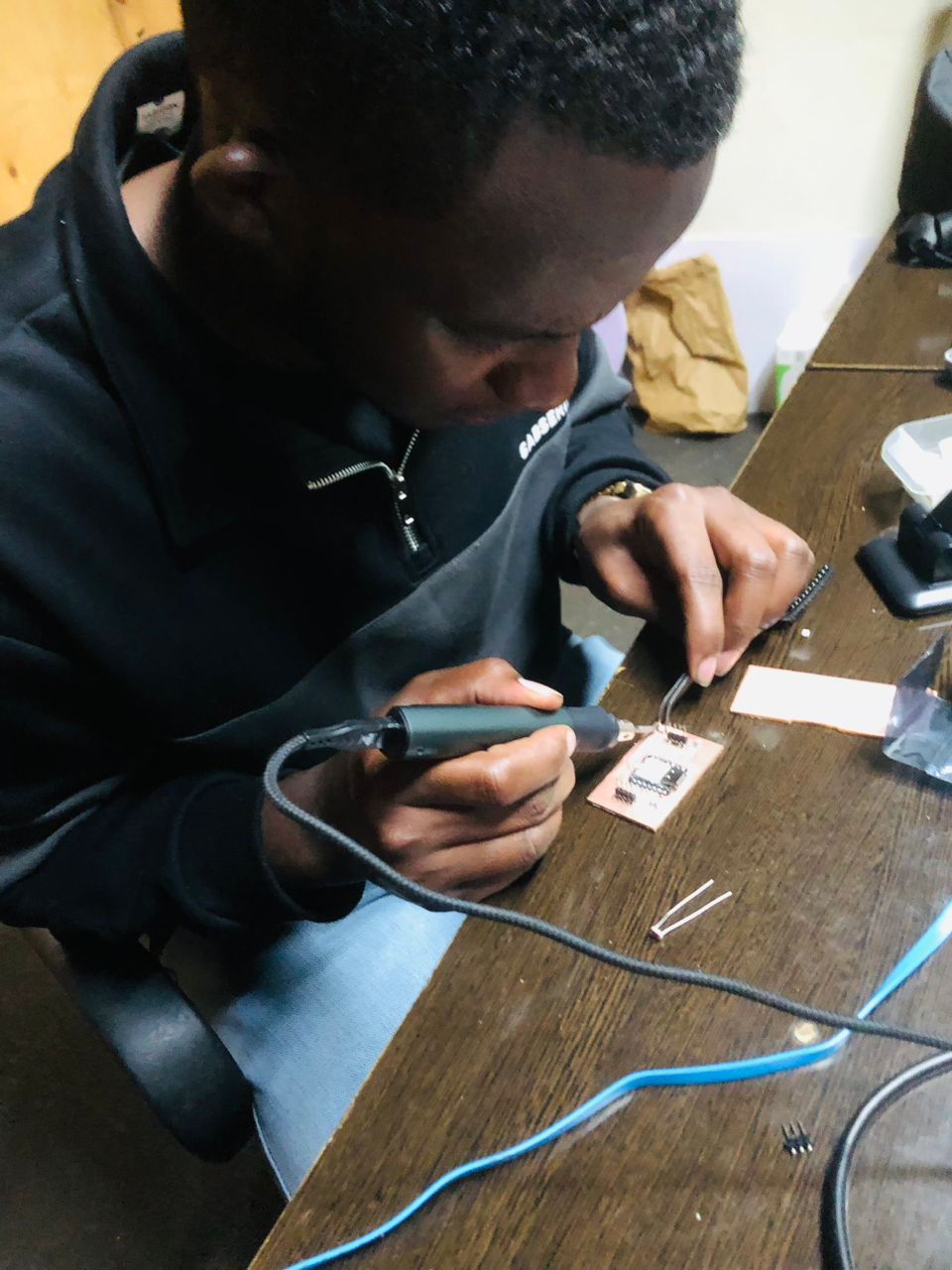
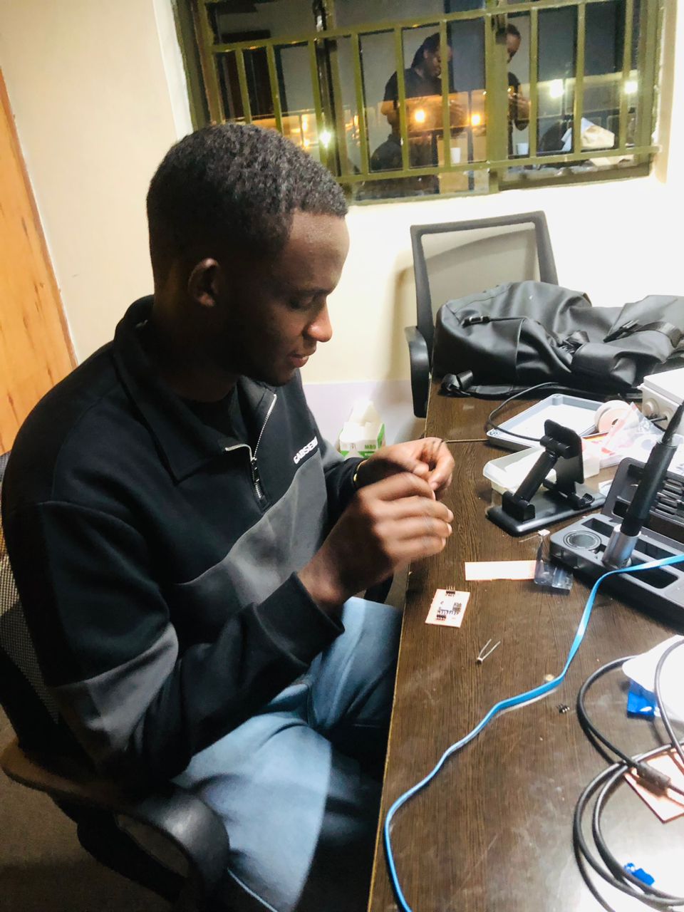
PCB Testing
After soldering all components on the PCB, I wrote a simple program to light the LED to check if the PCB was working correctly
This is my test code for the PCB
#define LDR_PIN A0
#define LED_PIN D1

int threshold = 20;

void setup() {
pinMode(LED_PIN, OUTPUT);
Serial.begin(115200);
}

void loop() {
int lightValue = analogRead(LDR_PIN);

Serial.println(lightValue);

// DARK → LED ON
if (threshold > lightValue) {
digitalWrite(LED_PIN, HIGH);
} else {
  digitalWrite(LED_PIN, LOW);
}

  delay(300);
}
#define LDR_PIN A0
#define LED_PIN D1
int threshold = 20;
void setup() {
pinMode(LED_PIN, OUTPUT);
Serial.begin(115200);
}
void loop() {
int lightValue = analogRead(LDR_PIN);
Serial.println(lightValue);
// DARK → LED ON
if (threshold > lightValue) {
digitalWrite(LED_PIN, HIGH);
} else {
digitalWrite(LED_PIN, LOW);
}
delay(300);
}
After that, I completed the code.
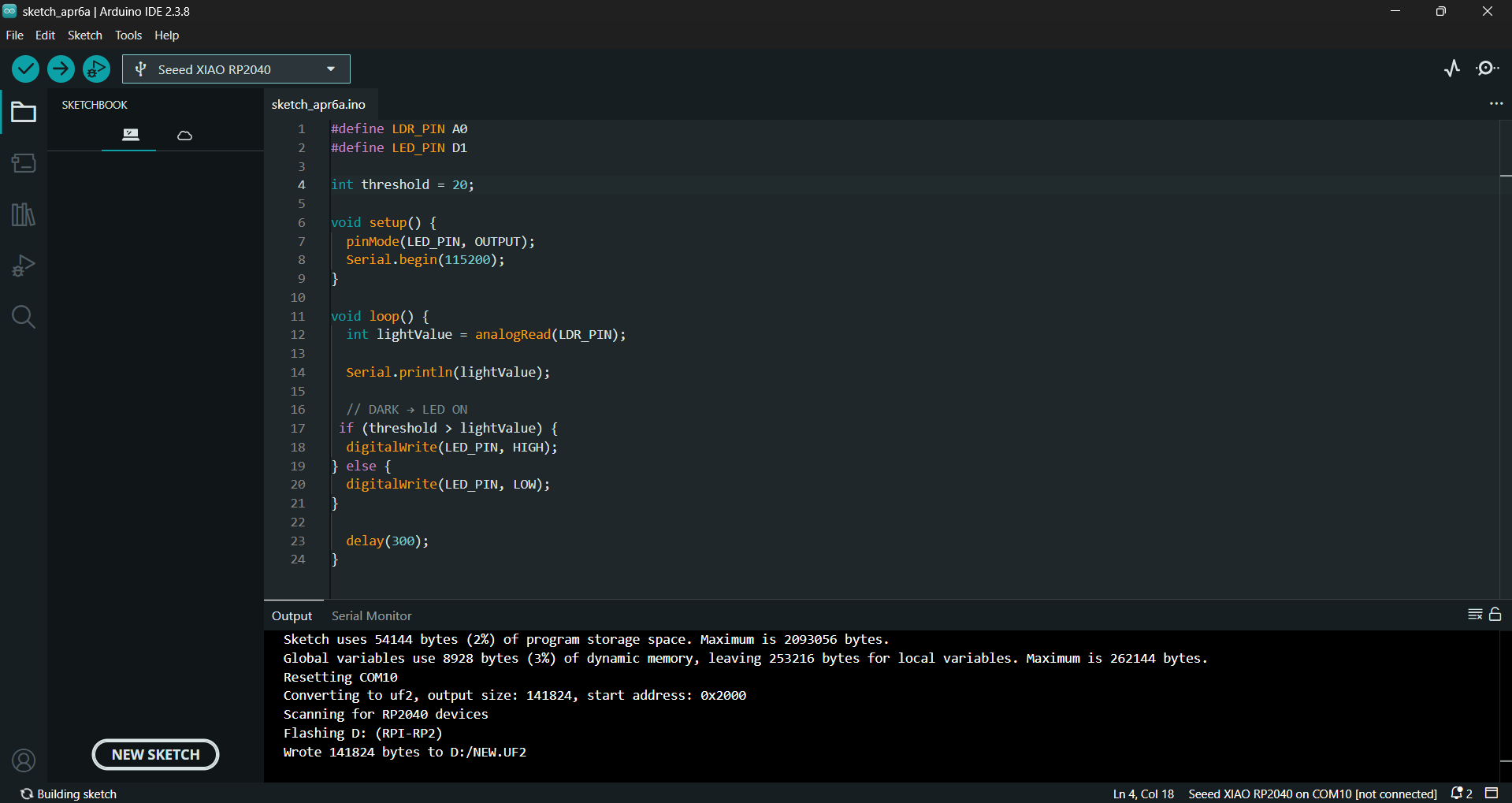
Testing Outcome
The script successfully blinked the LED, confirming that the PCB is functioning correctly