
A plywood pen plotter.
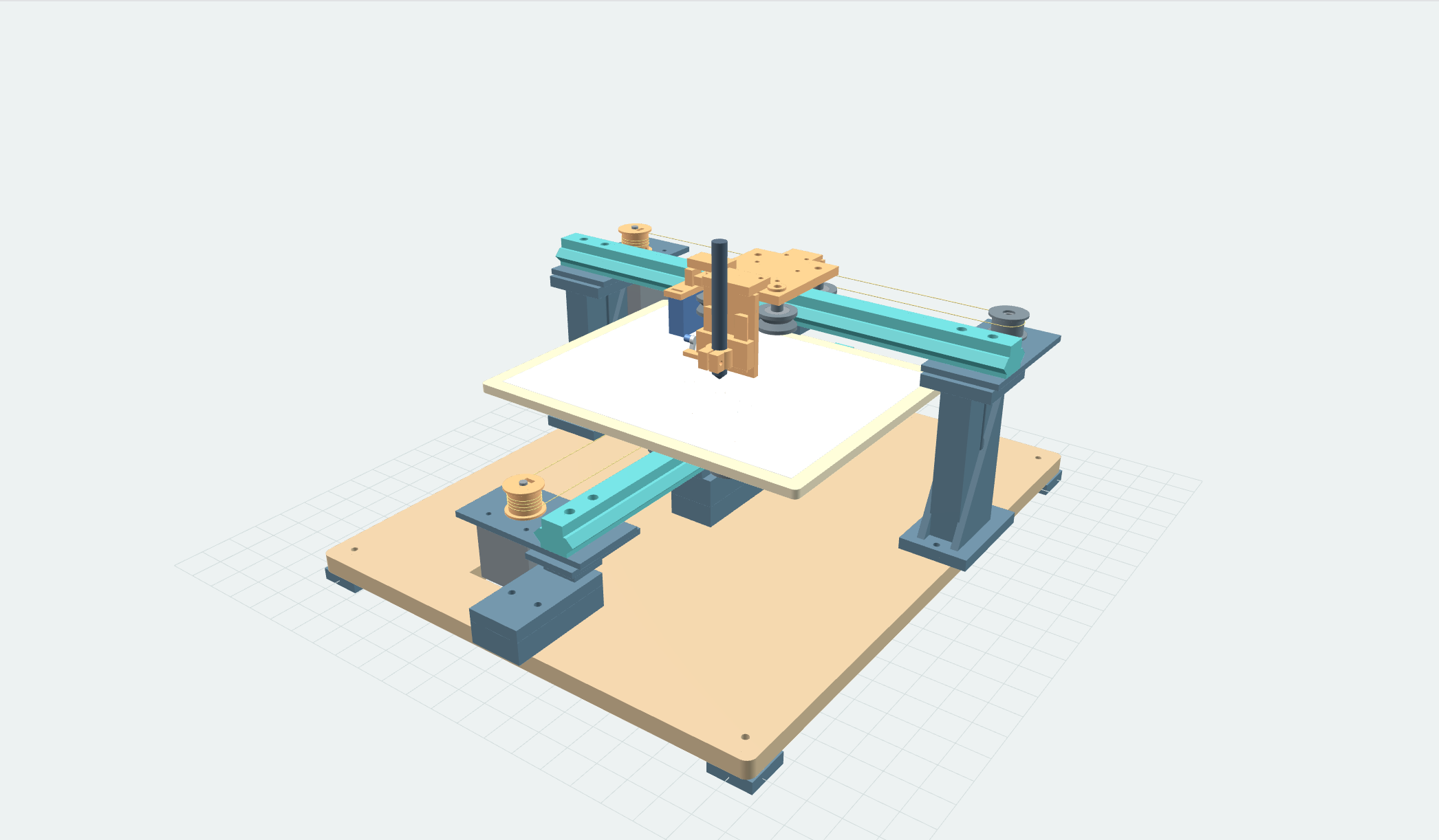
We are developing a compact machine that moves a pen across X and the paper bed along Y. We use a CNC-cut plywood base and bed, printed rails, adjustable roller carriages and a servo pen lift for a 200 × 150 mm drawing area. The motion design takes inspiration from the Fab Lab Oulu bootcamp linear axis.
This is our CAD prototype. The files describe the intended assembly; printing, fitting, control configuration and physical plotting tests come next.
Loading the CAD assembly…
How the mechanism works
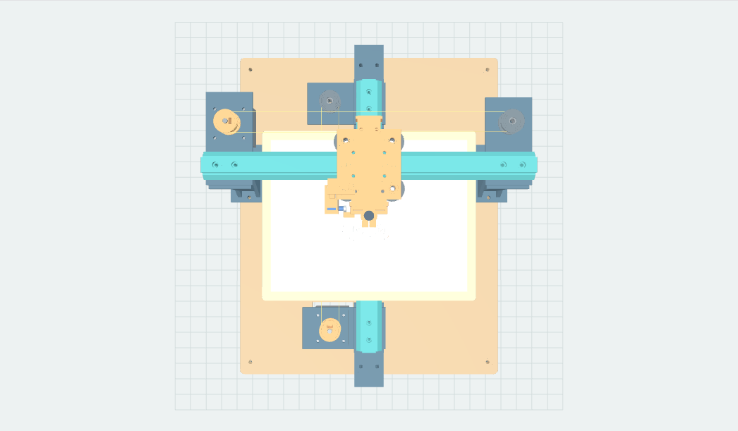
The X beam stays fixed between two printed towers. A motor capstan pulls low-stretch cord to move its four-wheel carriage and pen holder. Below it, a second cord drive moves the paper bed along Y. Moving the paper reduces the load on the X carriage. The base is about 326 × 400 mm, with small support overhangs.
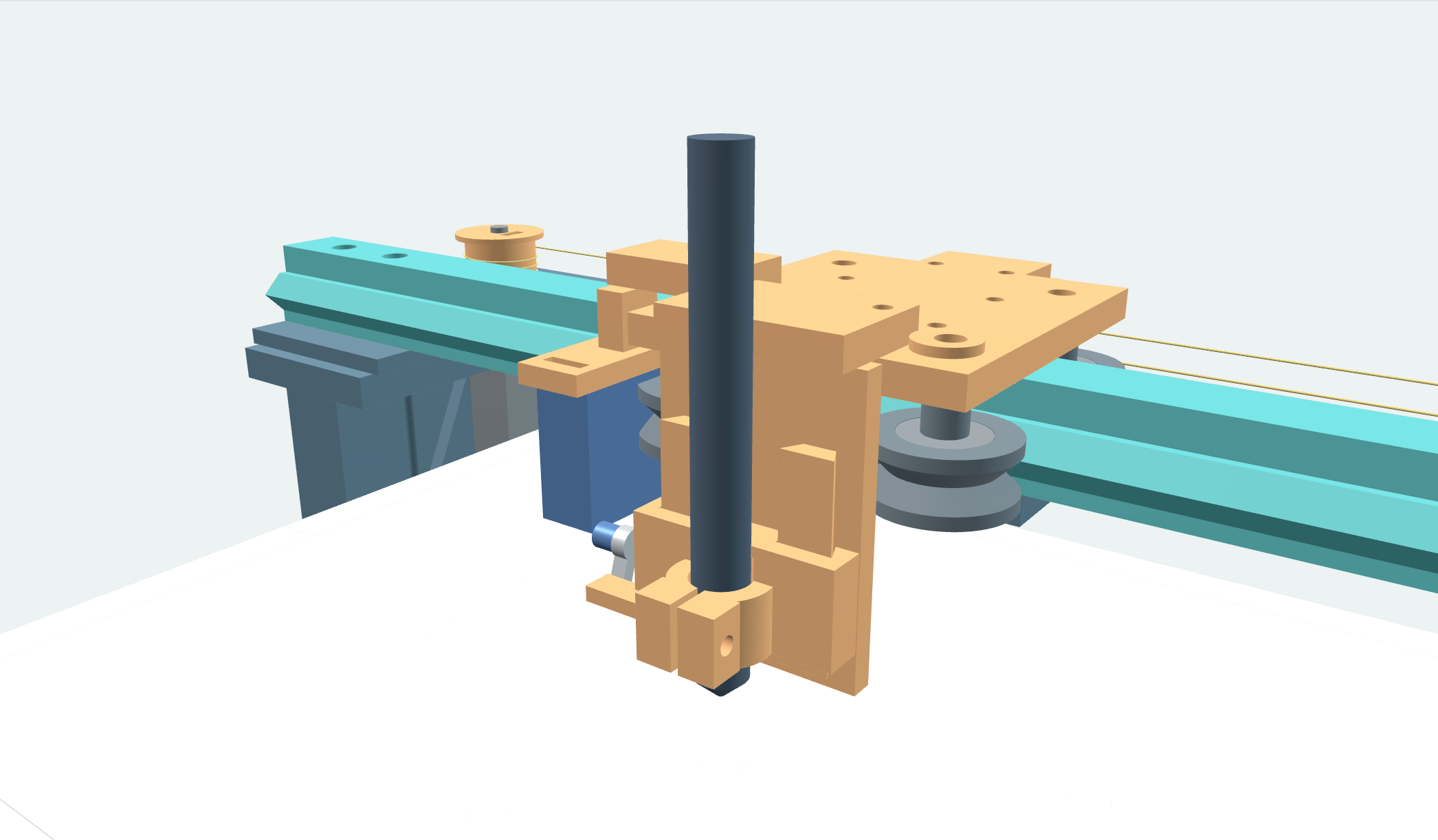
Each carriage has two fixed wheel positions and two eccentric bushes. The bushes let us adjust contact with the printed V faces. Each wheel contains two bearings and an inner-race spacer. The rails have a central reinforcing spine and bolted underside joints; the running faces must stay aligned at those joints.
The pen holder slides vertically on two printed dovetail guides. A side-mounted servo horn lifts its pickup tab, while the pen returns under its light weight. We will fit the actual horn and set its angles on the first assembly. The preview shows up to 6 mm of geometric slide travel; it is not a measured servo stroke.
What we changed from the reference
The Oulu bootcamp project demonstrates a printable NEMA 17 linear axis with a roller carriage and a FreeCAD rail-length parameter. We studied its README, native model, photographs and mesh parts at commit 603c2b3.
Our CAD is new geometry. We use four wheels per carriage, split printed rails for a 200 mm printer bed, CNC-cut plywood panels, adjustable wheel preload and a dedicated pen lift. We did not copy the upstream STL or FreeCAD bodies into this package.
Hardware we recommend
We use a 12 mm plywood base and a 6 mm plywood paper bed, with printed rails, towers, carriages, capstans, adapters and pen mechanism. Motors, bearings, low-stretch cord and fasteners are purchased components.
| Component | Quantity | Design specification |
|---|---|---|
| Plywood base | 1 | 326 × 400 × 12 mm; CNC-cut from measured stock. |
| Plywood paper bed | 1 | 240 × 190 × 6 mm; four top screw-head recesses. |
| NEMA 17 bipolar steppers | 2 | 42 mm face; 31 mm mounting pitch; 5 mm shaft; body ≤40 mm in this model. |
| 625 bearings | 20 | 16 in carriage wheels, 4 in the two cord idlers; 5 × 16 × 5 mm. |
| Low-stretch cord | About 3 m allowance | Nominal 0.5 mm braided cord; leave anchoring tails and trim after routing. |
| SG90-class servo | 1 | Supplied horn and screw; physical lift fitting still required. |
| XIAO RP2040 | 1 | grblHAL over native USB, using our board map and PWM servo plugin. |
| External PUL/DIR drivers | 2 | Match the motor rating; identify the input voltage/current before choosing the interface. |
| X/Y home switches | 2 | Fit at the verified carriage endpoints. |
| Power supplies | Motor supply + regulated 5 V | Motor voltage follows driver requirements; servo rail uses a common signal ground. |
| Fasteners and supplies | See BOM | M3/M4/M5 bolts, nuts, washers, cable ties, light pen and paper. |
With a 200-step motor, 1/16 microstepping, a 20 mm capstan and 0.5 mm cord, the calculated starting scale is 200 × 16 ÷ (π × 20.5) ≈ 49.687 steps/mm. Calibrate this against measured travel. Physical paper-bed motion reverses drawing Y, so verify direction and the origin with short jogs.
We selected a XIAO RP2040 running grblHAL over USB. Our board map uses two PUL/DIR drivers and the PWM servo plugin for pen lift. Read the controller guide for the pin map, build instructions and calibration. The driver model determines whether its inputs require a 3.3 V-to-driver interface.
CNC plywood base and bed
We can cut a 12 mm plywood base and a 6 mm paper bed on a CNC router while printing the rails, carriages, capstans and pen mechanism. Printed risers and spacers preserve the same rail and paper heights. The base includes a Y-motor clearance window and matching mounting holes.
CNC files, print list and mounting guide
Prepare a drawing
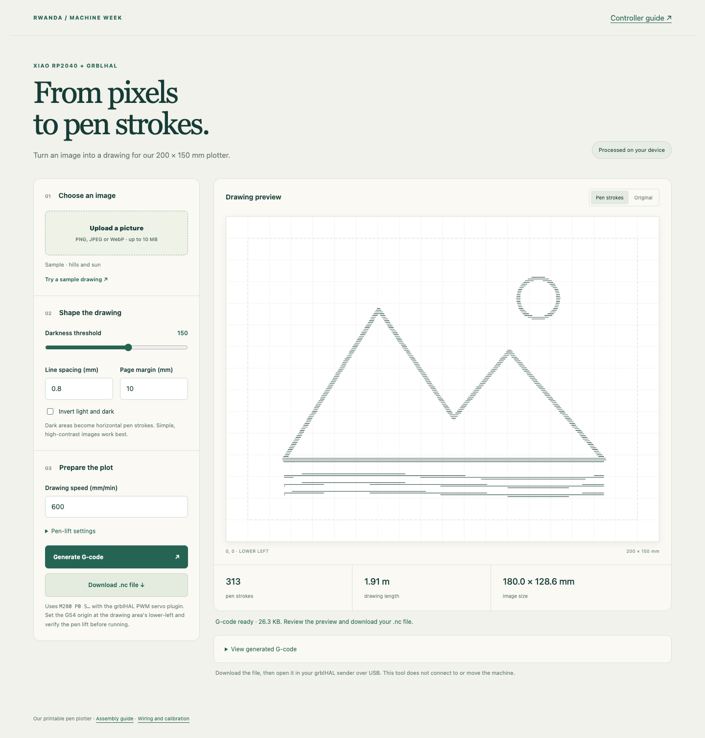
We use a XIAO RP2040 with grblHAL over USB. Our image tool turns a picture into horizontal pen strokes within the 200 × 150 mm drawing area. We can adjust the darkness threshold, spacing, margin and pen angles, preview the result and download G-code for a grblHAL sender. Image processing stays in the browser.
Printing and assembly
This build requires 66 printed pieces across 24 part types, plus an optional fit coupon. The largest required XY dimension is 174.9 mm and the tallest part is 116 mm. All printed parts fit a 200 × 200 mm printer with a 5 mm brim allowance per side. Print at 100% scale in millimetres.
We will print the bearing-fit coupon first, then a wheel and a short rail check before committing to the full set. The nominal bearing-seat size and slide clearance are parameters, because the actual fit depends on the printer and material. PLA is a starting choice for stiff rails/frame parts, with PETG an option for wheels and sliding pieces.
- Route the plywood base and bed using the measured stock thickness. Deburr holes and edges, then fit the four base feet.
- Fit the towers and Y supports. Keep the rail screw heads below the upper spine.
- Assemble the bearing wheels, spacers and eccentric bushes. Check each carriage by hand over the rail joint.
- Install motors, printed capstans and bearing idlers. Route 3½ separated cord wraps and adjust light tension without bending the supports.
- Mount the plywood paper bed on its four printed spacers with recessed screw heads, then mount the pen stage.
- Fit the servo horn, set a small lift and verify the mechanism before powered X/Y motion.
Suggested first-print settings are a 0.4 mm nozzle, 0.20 mm layers, 4–5 perimeters and 30–40% infill. These are proposed settings, not recorded print results. Inspect the slicer preview for local support needs, especially at the servo platform and nut recesses, while protecting the running and sliding surfaces.
Read the complete assembly guide · Wiring and control plan · Hardware BOM
Design checks and first tests
We checked the printable parts for valid single solids, closed STL meshes and printer fit. The plywood assembly has zero detected structural-part intersections at nine sampled X/Y positions. These CAD checks do not establish fastener fit, stiffness, cord grip, wear or plotted accuracy.
Our first physical tests will be smooth manual motion over each rail seam, short motor jogs, repeated pen lifts and a measured square. We will compare line lengths, diagonals and return position before increasing speed or claiming the full operating area. The full build and its results will be added as we carry out those tests.
Editable CAD and print files
The Python CAD source and JSON parameters regenerate the individual STL/STEP parts, assembly STEP, visual model and print list. The assembly STEP preserves the assembled positions. Individual part exports are placed in their print orientation. Hardware envelopes in the assembly are for reference and are not print files.
Package guide · Design parameters · Print quantities (CSV)
| Printed part | Quantity | Print size (mm) | STL |
|---|---|---|---|
| Axle spacer | 8 | 8 × 8 × 8 | Download |
| Bearing inner spacer | 10 | 7.5 × 7.5 × 1.8 | Download |
| Carriage | 2 | 66 × 86 × 28 | Download |
| Cnc bed spacer | 4 | 12 × 12 × 16 | Download |
| Cnc centre riser | 1 | 32 × 64 × 15 | Download |
| Cnc corner foot | 4 | 28 × 28 × 8 | Download |
| Cnc end riser | 2 | 36 × 70 × 15 | Download |
| Cord return idler | 2 | 25 × 25 × 15 | Download |
| Eccentric bush | 4 | 12 × 12 × 7.8 | Download |
| Idler bracket | 2 | 50 × 94 × 6 | Download |
| Idler inner support | 2 | 7.5 × 7.5 × 3 | Download |
| Motor bracket | 2 | 50 × 100 × 4 | Download |
| Motor capstan | 2 | 25 × 25 × 20 | Download |
| Pen slider | 1 | 48 × 22.2 × 18 | Download |
| Pen stage | 1 | 66 × 65 × 36 | Download |
| Rail joiner | 2 | 66 × 20 × 6 | Download |
| V wheel | 8 | 26 × 26 × 12 | Download |
| X rail · left | 1 | 174.9 × 30 × 20 | Download |
| X rail · right | 1 | 174.9 × 30 × 20 | Download |
| X tower | 2 | 46 × 72 × 116 | Download |
| Y center foot | 1 | 32 × 64 × 19 | Download |
| Y end foot | 2 | 36 × 105 × 21 | Download |
| Y rail · left | 1 | 159.9 × 30 × 20 | Download |
| Y rail · right | 1 | 159.9 × 30 × 20 | Download |
| Bearing-fit test coupon | Optional | 76 × 28 × 6 | Download |
References and assistance
The starting reference is the 3D printable linear axis, developed during the Fab Lab Oulu instructors’ bootcamp. Its README credits Babken Chugaszyan, Quentin and Gleb Bulygin, and points to Neil Gershenfeld’s Urumbu work.
Component and control references: NEMA 17 dimension drawing, A4988 driver guidance, SG90 specifications and grblHAL PWM servo support. The parametric model uses CadQuery. The local viewer uses Three.js, with its MIT licence notice retained.
Codex assisted with reference analysis, the new CAD model, geometry checks and this documentation. We will validate the printed parts, hardware interfaces and operation through the group build. Individual contributions to fabrication and testing will be described when that work is performed.
Cord-drive reference: Quentin Bolsée’s Urumbu axis and capstan routing. Our capstan, anchors and roller are new geometry and use a different single-capstan route.