Interface and Application Programming
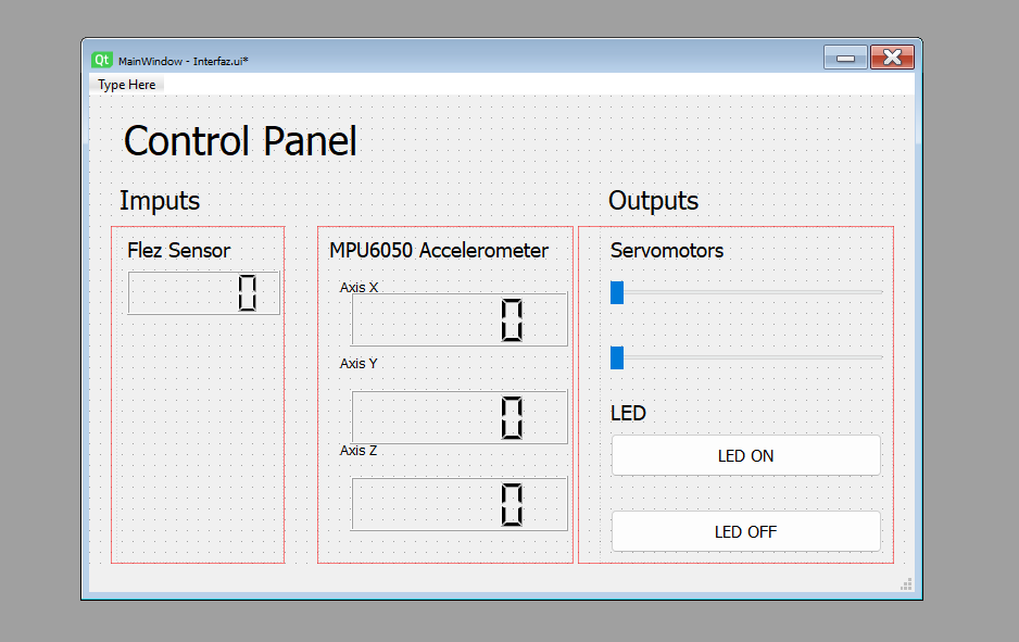
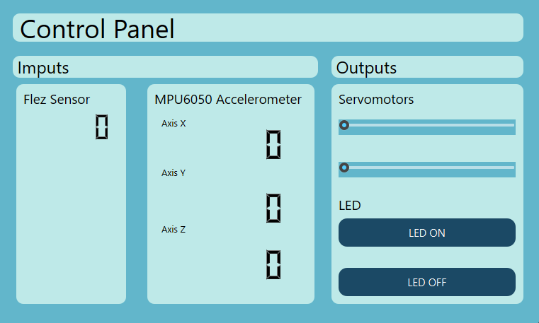
This week, I created an interface that reflected the 3-axis movement of an MPU6050 sensor and the bending of a flex sensor. I also added the ability to move servos using a slider. For the graphical aspect, I used QT Designer; for the interface programming, I used Python; and for data collection and servo movement, I used C++.
During the group assignment week, we compared three tools for building graphical user interfaces. We worked with Tkinter, a lightweight Python library good for simple prototypes, Qt Designer with PyQt6, which allowed us to design layouts visually and connect them to Python logic, and LabVIEW, a block-diagram-based environment focused on hardware interaction and data acquisition. For each tool we built a basic greeting app to understand the workflow and compare their strengths and limitations. The main takeaway was that the right tool depended on the complexity of the interface and the hardware integration needs of the project.
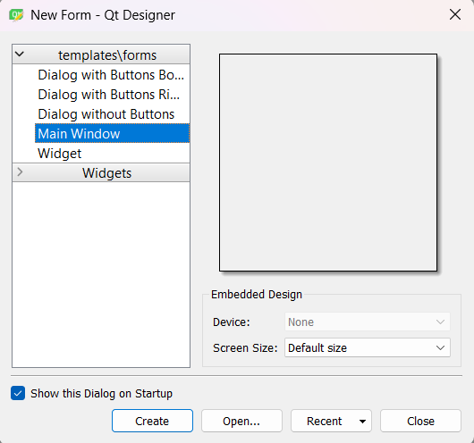
Group Assignment Week 14
Interface Design
QT Designer is a graphical user interface design tool that allowed me to build applications with a visual interface. It is part of the Qt development environment and facilitated the creation of windows, dialogs, and other user interface elements.
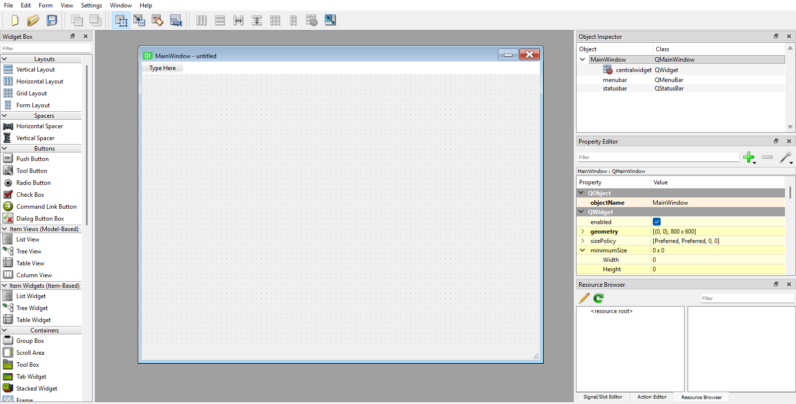
Using QT Designer's tools, I designed an intuitive user interface; however, it still needed refinement, such as adding color and style to the interface.
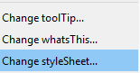
To add the styling, I right-clicked on the Main Window, clicked on "Change styleSheet", and a window opened where I could add CSS styles to customize the appearance of my interface.
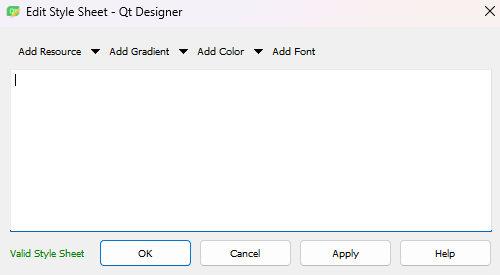
For the styling, I wrote the following CSS code:
QWidget{
background-color: rgb(98, 182, 203);
}
QPushButton{
background-color: rgb(27, 73, 101);
color: rgb(255, 255, 255);
border-radius:12px
}
QPushButton:hover{
background-color: rgb(95, 168, 211);
}
QPushButton:pressed{
background-color: rgb(202, 233, 255);
}

QFrame {
    background-color: #BEE9E8;
    border-radius: 10px;
}

* {
    color: black;
}
- QWidget: Painted the main background of the entire window blue.
- QPushButton: Defined the base design of the buttons: dark blue background and rounded corners.
- QPushButton:hover: Changed the button to a brighter blue when the cursor hovered over it, providing interactivity.
- QPushButton:pressed: Lightened the button's color when clicked, creating a visual sunken effect.
- QFrame: Styled the grouping containers by giving them a cream background and soft borders, creating a card layout.
- *: This was the universal selector; it forced the text of all interface elements to be black.
Interface Programming
To program the interface and make it functional, I needed to implement a Python script to handle the event logic and user interaction. First, I had to install certain libraries.
pip install PyQt6 pyserial
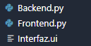
With the libraries installed, I could start programming the interface. I created a new folder to save the .ui file generated by QT Designer. I also generated two .py files: the backend, which contained the interface's logic, and the frontend, which handled the programming of the interface's visualization.
A crucial step was converting the .ui file generated by QT Designer into the frontend's .py file to make the interface functional. To do this, I used the following command in the terminal:
pyuic6 Interfaz.ui -o Frontend.py
With this, the .ui file was converted into the frontend .py file. This file defined the interface elements along with their positions and styles, but it was not functional yet. For that, I needed to program the backend to handle the event logic and user interaction.
import sys
import serial
from PyQt6 import QtCore, QtGui, QtWidgets
from Frontend import Ui_MainWindow

class MainWindow(QtWidgets.QMainWindow, Ui_MainWindow):
    def __init__(self, *args, **kwargs):
        super(MainWindow, self).__init__(*args, **kwargs)
        self.setupUi(self)

        #  1. SERIAL CONFIGURATION
        self.serial_port = 'COM3'
        self.baud_rate = 115200

        try:
            self.ser = serial.Serial(self.serial_port, self.baud_rate, timeout=0.01)
            print(f"Successfully connected to {self.serial_port}")
        except Exception as e:
            print(f"WARNING: Board not detected on {self.serial_port}. Simulation mode active.")
            print(f"Details: {e}")

        #  2. TIMER FOR SENSOR READINGS INPUTS
        self.sensor_timer = QtCore.QTimer()
        self.sensor_timer.timeout.connect(self.read_sensor_data)
        self.sensor_timer.start(50)

        #  3. CONTROLS CONNECTION OUTPUTS
        # LED Buttons
        self.BTNLEDON.clicked.connect(self.turn_on_led)
        self.BTNLEDOFF.clicked.connect(self.turn_off_led)

        # Servo Sliders
        self.SLRServo_1.valueChanged.connect(self.control_servo_1)
        self.SLRServo_2.valueChanged.connect(self.control_servo_2)

    #  METHODS FOR INPUTS
    def read_sensor_data(self):
        if hasattr(self, 'ser') and self.ser.in_waiting > 0:
            try:
                # READ EVERYTHING IN THE BUFFER
                lines = self.ser.readlines()
                if not lines:
                    return

                last_line = lines[-1].decode('utf-8').strip()
                data = last_line.split(',')

                if len(data) == 4:
                    self.Flex_Sensor.display(data[0])
                    self.Axis_X.display(data[1])
                    self.Axis_Y.display(data[2])
                    self.Axis_Z.display(data[3])

            except Exception as e:
                pass

    #  METHODS FOR OUTPUTS
    def turn_on_led(self):
        print("Sending: LED ON")
        self.send_command("L1")

    def turn_off_led(self):
        print("Sending: LED OFF")
        self.send_command("L0")

    def control_servo_1(self):
        angle = self.SLRServo_1.value()
        self.send_command(f"S1:{angle}")
        print(f"S1:{angle}")

    def control_servo_2(self):
        angle = self.SLRServo_2.value()
        self.send_command(f"S2:{angle}")
        print(f"S2:{angle}")

    def send_command(self, command):
        """Auxiliary function to send data via serial"""
        if hasattr(self, 'ser'):
            try:
                # We send the command with a line break so the board knows where it ends
                self.ser.write(f"{command}\n".encode())
            except Exception as e:
                print(f"Error sending: {e}")

if __name__ == "__main__":
    app = QtWidgets.QApplication(sys.argv)
    window = MainWindow()
    window.show()
    sys.exit(app.exec())
Libraries and Imports
import sys: Imported the system module, necessary to interact with the operating system and close the application safely.import serial: Included the pyserial library, the core for establishing physical communication via the USB/COM port.from PyQt6 import...: Imported the base modules of the Qt framework to create and manage the graphical interface.from Frontend import Ui_MainWindow: Imported the design class automatically generated from my QT Designer file.
Class Initialization & Serial Setup
class MainWindow(...): Created the main class using multiple inheritance to get the properties of the window and my visual design.self.setupUi(self): Drew and initialized all the widgets and configurations I created in QT Designer.self.baud_rate = 115200: Defined the communication speed. It had to match the microcontroller's speed exactly.serial.Serial(..., timeout=0.01): Opened the port. An extremely low timeout prevented the graphical interface from freezing if there were connection delays.
Timers and UI Connections
QtCore.QTimer(): Created a non-blocking internal clock that allowed executing functions in the background without freezing the screen.self.sensor_timer.start(50): Instructed the timer to execute the reading every 50 milliseconds (20Hz).- Signals and Slots:
.clicked.connect(...)linked the user's click to a function, while.valueChanged.connect(...)triggered commands automatically when I moved the slider.
Sensor Data Processing (Inputs)
This section prevented lag when processing information. Instead of reading line by line and falling behind, it extracted the entire accumulated buffer and processed only the most recent reading to reflect the hardware's current state.
self.ser.in_waiting > 0: Verified if bytes had arrived in the computer's buffer before attempting to read.self.ser.readlines(): Read all accumulated lines at once, clearing the queue of pending data.lines[-1]: Selected only the last position of the list, ensuring that the freshest data was processed..decode('utf-8').strip(): Converted raw bytes into readable text and removed invisible line breaks.split(','): Cut the comma-separated text string into a list of individual values to update each LCD screen independently.
Output Control & Execution
self.SLRServo_1.value(): Extracted the current integer numerical value (0 to 100) from the slider.f"{command}\n": Injected a line break at the end of the command. The microcontroller needed this character to know where the instruction ended.self.ser.write(...): Physically pushed the information from Python to the board..encode(): Transformed the text string back into pure bytes, since the hardware cannot process abstract text.app.exec(): Started the Qt Event Loop, keeping the window open and listening for user interactions.
With this code, the graphical interface became fully functional, allowing both the real-time visualization of sensor data and the control of actuators through buttons and sliders.
For the microcontroller to respond to the interface's control signals, I had to implement the logic within the microcontroller's C++ code to interpret the commands received through the serial port and execute the corresponding actions, such as turning an LED on or off, or moving a servo to a specific angle.
String inputString = "";
bool stringComplete = false;

void setup() {
  Serial.begin(115200);
  inputString.reserve(50);
}

void loop() {
  int valorFlex = 50;
  float aceX = 0.5;
  float aceY = -0.2;
  float aceZ = 0.9;

  Serial.print(valorFlex);
  Serial.print(",");
  Serial.print(aceX);
  Serial.print(",");
  Serial.print(aceY);
  Serial.print(",");
  Serial.println(aceZ);

  while (Serial.available()) {
    char inChar = (char)Serial.read();

    if (inChar == '\n') {
      stringComplete = true;
    } else {
      inputString += inChar;
    }
  }

  if (stringComplete) {
    inputString.trim();

    if (inputString.startsWith("S1:")) {
      int valorSlider = inputString.substring(3).toInt();
    }
    else if (inputString.startsWith("L")) {
      int estadoLed = inputString.substring(1).toInt();
    }

    inputString = "";
    stringComplete = false;
  }

  delay(20);
}
The bidirectional communication strategy between the board and the computer operated asynchronously at 115200 baud. It was divided into two key processes: packaging the sensor data to send to the graphical environment, and a non-blocking "active listening" system to receive instructions back.
Sending Data
To send the input information, I structured a simple text message using a comma-separated format.
- Structuring (CSV): Using
Serial.print(",")chained the readings of the flex sensor and the accelerometer axes into a single continuous line. - The Final Delimiter: The
Serial.println()instruction on the last reading injected a line break (\n) at the end of the message. This character was crucial, as it told Python that the current data packet had finished and was ready to be processed.
Receiving Commands (Python to Arduino)
To receive actions (outputs), the microcontroller assembled the data character by character until forming a complete instruction, avoiding the use of delays that would freeze the board.
Serial.available(): Constantly checked the USB port memory to see if new bytes of information had arrived from the Python interface.- Message Assembly:
(char)Serial.read()captured each individual letter or number and added it to the temporary memory variableinputString. - Completion Flag:
if (inChar == '\n')detected the line break sent by Python. Once found, it activated the boolean variablestringComplete = true, notifying the main program that the message was ready to be interpreted. - Decoding (Parsing): The
.startsWith("S1:")function read the prefix to know which hardware to activate. Then,.substring(3).toInt()ignored that initial text, extracted only the numerical part, and converted it into an integer value that the board could use mathematically.
The rest of the code responsible for reading the sensor data and sending the PWM signal to the servo can be found in the Inputs and Outputs Devices weeks. If you want to check the full code, you can go to the following links:
Imputs Devices
Outputs Devices