Inputs Devices
For this week's group assignment, we reviewed the fundamental differences between signal types and communication protocols. We characterized analog signals as continuous voltage fluctuations operating in a range of 0 V to 3.3 V on our boards and contrasted them with digital signals, which are based on discrete binary states of High or Low. We also analyzed the Inter-Integrated Circuit or I2C protocol, breaking down how it uses only two wires SDA for serial data transmission and SCL for clock synchronization to send structured digital packets between a microcontroller and various peripherals.
To physically observe this theoretical knowledge, we used laboratory diagnostic tools to observe the sensors in operation. First, we used a multimeter to analyze the analog voltage divider circuit. By applying a change to the analog sensors, we observed the voltage fluctuation in real time. Separately, we connected the oscilloscope probes directly to the SDA and SCL traces of the accelerometer. This allowed us to visualize the high-speed I2C communication protocol, revealing the precise and discrete 0V Low and 3.3V High square waves of the digital clock pulses and data packets. Visualizing both the continuous analog waveform and the sharp digital pulses on the instruments allowed us to establish a clear connection between electronic theory and physical reality.
Group Assignment Week 9
I focused on integrating input devices into the PCB I designed last week. My main goal was to read data from the sensors and see it displayed on the Serial Monitor.
Electronics Production
Initially, I tried using the Seeed Studio XIAO RP2350 as my main microcontroller. However, I encountered significant technical obstacles, especially regarding the stability of the I2C communication. After several failed attempts to get the bus recognized, I decided to change my strategy to achieve my goal. I swapped the RP2350 for a XIAO ESP32-C3. This change proved to be the right move, as the ESP32-C3 immediately handled the communication protocols much more effectively, allowing me to move forward with my sensor integration.
Once the new microcontroller was in place, I successfully implemented two different inputs:
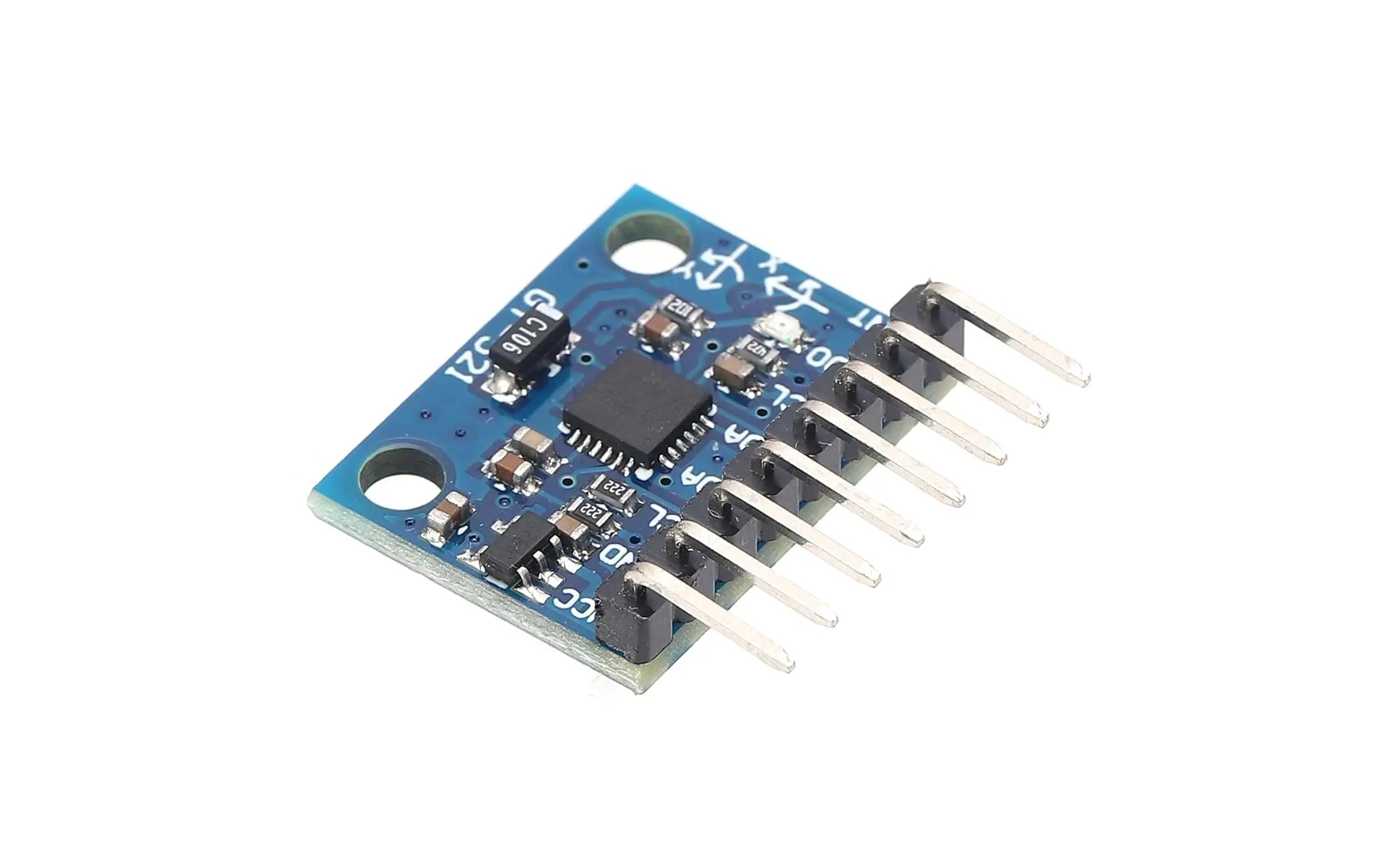
- I programmed a MPU6050 IMU, a 6-axis sensor to track motion and orientation.
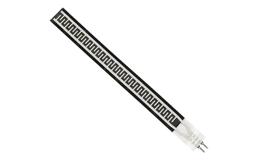
- I utilized a carbon-based flex sensor as my primary analog input to capture physical bending. By reading the analog values from this sensor, I created a control loop to map its fluctuating resistance directly to the brightness of the programmable LED integrated into my board design.
Programming the Xiao-ESP32-C3
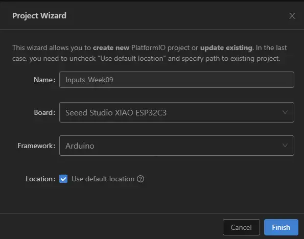
For this week's programming assignments, I decided to stop using the basic Arduino IDE and switch to Visual Studio Code with the PlatformIO extension. While the Arduino IDE is a good starting point, I needed a more robust and professional environment.


Programming and Testing Inputs
MPU6050
Flex Sensor
#include <Arduino.h>
#include <Wire.h>
#include <MPU6050.h>

#define SDA_PIN 6
#define SCL_PIN 7

MPU6050 MPU;

const int Num_Reading = 10;

float Readings_Gyr_X[Num_Reading];
float Readings_Gyr_Y[Num_Reading];
float Readings_Gyr_Z[Num_Reading];

int Index = 0;
float Add_Gyr_X = 0.0, Add_Gyr_Y = 0.0, Add_Gyr_Z = 0.0;
float Avar_Gyr_X = 0.0, Avar_Gyr_Y = 0.0, Avar_Gyr_Z = 0.0;

const float GYRO_SCALE_FACTOR = 65.5;

void setup() {
  Serial.begin(115200);
  Wire.begin(SDA_PIN, SCL_PIN);

  Serial.println("Inizalizating MPU6050...");

  MPU.initialize();

  if (!MPU.testConnection()) {
    Serial.println("MPU6050 no conected");
    while (1);
  }

  MPU.setFullScaleGyroRange(MPU6050_GYRO_FS_500);

  Serial.println("Gyroscope Ready.");

  for (int i = 0; i < Num_Reading; i++) {
    Readings_Gyr_X[i] = 0.0;
    Readings_Gyr_Y[i] = 0.0;
    Readings_Gyr_Z[i] = 0.0;
  }
}

void loop() {
  int16_t gx, gy, gz;

  MPU.getRotation(&gx, &gy, &gz);

  float gyr_x_dps = gx / GYRO_SCALE_FACTOR;
  float gyr_y_dps = gy / GYRO_SCALE_FACTOR;
  float gyr_z_dps = gz / GYRO_SCALE_FACTOR;

  Add_Gyr_X -= Readings_Gyr_X[Index];
  Add_Gyr_Y -= Readings_Gyr_Y[Index];
  Add_Gyr_Z -= Readings_Gyr_Z[Index];

  Readings_Gyr_X[Index] = gyr_x_dps;
  Readings_Gyr_Y[Index] = gyr_y_dps;
  Readings_Gyr_Z[Index] = gyr_z_dps;

  Add_Gyr_X += Readings_Gyr_X[Index];
  Add_Gyr_Y += Readings_Gyr_Y[Index];
  Add_Gyr_Z += Readings_Gyr_Z[Index];

  Index++;
  if (Index >= Num_Reading) {
    Index = 0;
  }

  Avar_Gyr_X = Add_Gyr_X / Num_Reading;
  Avar_Gyr_Y = Add_Gyr_Y / Num_Reading;
  Avar_Gyr_Z = Add_Gyr_Z / Num_Reading;

  Serial.print("Gyroscope X: "); Serial.print(gyr_x_dps);
  Serial.print(" | Gyroscope X_Average:"); Serial.print(Avar_Gyr_X);
  Serial.print(" Gyroscope Y: "); Serial.print(gyr_y_dps);
  Serial.print(" | Gyroscope Y_Average:"); Serial.print(Avar_Gyr_Y);
  Serial.print(" Gyroscope Z: "); Serial.print(gyr_z_dps);
  Serial.print(" | Gyroscope Z_Average:"); Serial.println(Avar_Gyr_Z);

  delay(50);
}
The MPU6050 is an advanced 6-axis digital inertial measurement unit. Its internal gyroscope continuously measures angular velocity, the rate at which the sensor actively rotates around its X, Y, and Z axes in space.
Libraries and Definitions
#include <MPU6050.h>: A library developed by Electronic Cats. It provides low-level hardware control over the sensor's registers, allowing direct access to raw data and advanced internal features.MPU6050 MPU;: Instantiates the main sensor object. Even though the I2C address is not explicitly defined in the code, this library is hardcoded to target the0x68default address, which matches my physical hardware configuration AD0 tied to GND.
Variables Configuration and Memory Allocation
#define SDA_PIN 6and#define SCL_PIN 7: Allows the reassignment of the default I2C communication pins for the XIAO ESP32-C3 through hardware multiplexing.const float GYRO_SCALE_FACTOR = 65.5: A vital mathematical constant derived from the sensor's datasheet. When the gyroscope is set to a ±500 Degrees Per Second range, the hardware outputs 65.5 raw digital points for every 1 degree of physical rotation.const int Num_Reading = 10: Defines the size of the memory window for the Simple Moving Average filter, balancing signal stability and responsiveness.float Readings_Gyr_X[...]: These arrays act as the physical memory blocks, storing the historical angular velocity data.float Add_Gyr_X = 0.0: Stores the running total of the buffer to avoid the heavy processing cost of mathematically adding all 10 array elements from scratch in every single loop.
Hardware Setup and Configuration
MPU.initialize()andMPU.testConnection(): Wakes up the sensor on the I2C bus and verifies the physical connection. If the sensor is not detected, the program deliberately halts to prevent null mathematical errors.MPU.setFullScaleGyroRange(MPU6050_GYRO_FS_500): Configures the sensor's internal registers to measure a maximum rotation of ±500 DPS. This is crucial to ensure the hardware's output matches the software'sGYRO_SCALE_FACTORfor accurate unit conversion.
Signal Processing: Circular Buffer SMA Algorithm
- Unit Conversion: The Electronic Cats library outputs raw, 16-bit integer gyroscope data (
gx). Before entering the memory buffer, this raw number is divided by the scale factor (gx / GYRO_SCALE_FACTOR) to convert it into human-readable Degrees per second. - Subtract the Old:
Add_Gyr_X -= Readings_Gyr_X[Index]removes the oldest recorded value from the running total before it gets overwritten in the memory array. - Store and Add the New: The newly converted DPS reading is saved into the current index slot (
Readings_Gyr_X[Index] = gyr_x_dps) and immediately added to the running total. - Calculate the Average: Finally, the updated running total is divided by the window size (
Avar_Gyr_X = Add_Gyr_X / Num_Reading) to yield the clean, filtered rotational velocity.
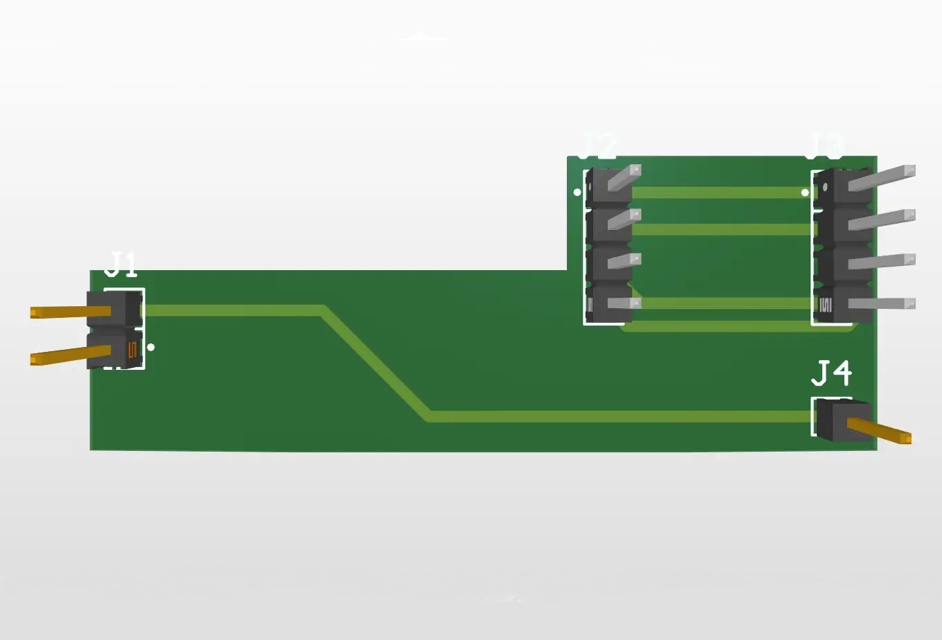
Hardware Design
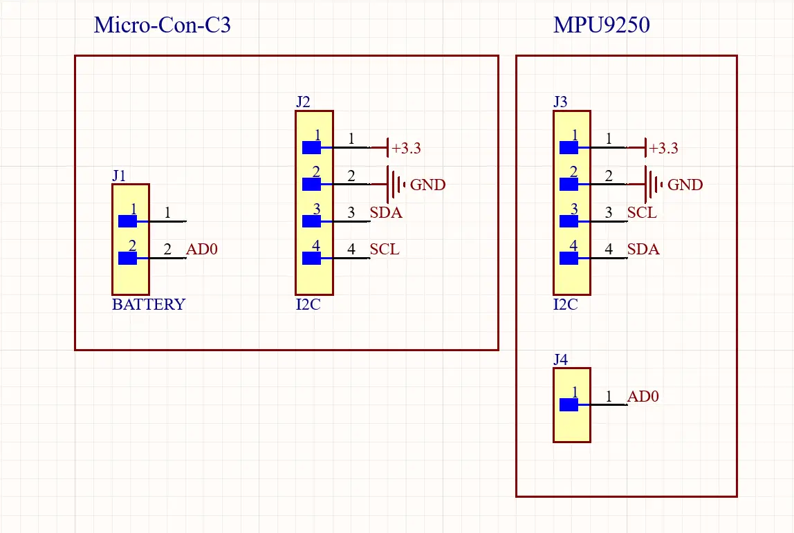
Since the MPU6050 gyroscope communicates via the I2C protocol, this board required precise routing for 4 main pins: VCC, GND, SDA,
and SCL. Additionally, I explicitly routed the AD0 pin to GND.
The AD0 pin acts as a hardware I2C address selector. By tying it low to GND, I permanently locked the
sensor's I2C address to 0x68. Leaving this pin floating could cause the address to randomly fluctuate between 0x68 and 0x69 due to
electromagnetic interference, which would instantly crash the communication loop. The primary goal of
this breakout board was to provide a secure physical mount, a stable hardcoded address that perfectly matches the default parameters of the Electronic Cats library, and clean
signal paths to the main microcontroller.
For the schematic design, I intentionally omitted external pull-up resistors on the I2C lines. Because I am using a pre-assembled commercial MPU6050 module, it already features internal 10kΩ pull-up resistors soldered directly to the SDA and SCL traces. Adding a redundant set of resistors on my custom PCB would place them in parallel with the module's internal ones, drastically lowering the equivalent resistance. This could draw excessive current and prevent the microcontroller from properly pulling the data lines down to 0V, corrupting the digital signal.
Modular I2C PCB
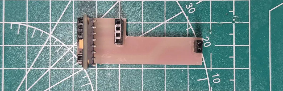
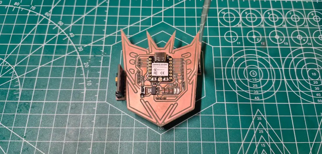
Final Result
#include <Arduino.h>

#define Flex_Sensor 2
#define LED 8

float Filter_Value = 0;
float Smooth_Factor = 0.3;

void setup() {
  pinMode(LED, OUTPUT);
  Serial.begin(115200);
}

void loop() {
  int Flex_Value = analogRead(Flex_Sensor);
  Filter_Value = Filter_Value * (1 - Smooth_Factor)
  + Flex_Value * Smooth_Factor;

  float Normalized_Value = Filter_Value / 3370.0;
  Normalized_Value = constrain(Normalized_Value, 0, 1);

  float Normalized_Value_Corrected = pow(Normalized_Value, 10.0);

  int LED_Brightness = Normalized_Value_Corrected * 255;

  analogWrite(LED, LED_Brightness);

  Serial.print("Crude Value: ");
  Serial.print(Flex_Value);
  Serial.print(" | Filtered: ");
  Serial.print(Filter_Value);
  Serial.print(" | Corrected: ");
  Serial.print(Normalized_Value_Corrected);
  Serial.print(" | LED Brightness: ");
  Serial.print((Normalized_Value_Corrected) * 100);
  Serial.println("%");

  delay(50);
}
The carbon-based flex sensor is a passive analog component designed to measure direct structural deformation. As an analog device, it outputs a continuous, fluctuating voltage signal based on its physical state; specifically, its electrical resistance increases as the carbon-ink layer is bent.
Pins and Variables Configuration
#define Flex_Sensor 2: Assigns the analog input pin for the flex sensor.#define LED 8: Assigns the digital output pin for the LED PWM signal.float Filter_Value = 0: Initializes the variable that acts as the memory for the low-pass filter.float Smooth_Factor = 0.3: Determines the weight of the EMA filter. It trusts the new sensor reading by 30% and retains 70% of the previous state to eliminate electrical noise. The balance of stability and speed of change.
Signal Processing: EMA Filter and Normalization
Once the signal is clean, the microcontroller normalizes the data:
Filter_Value / 3370.0: Converts the raw analog data (which maxes out at 3370 when physically bent) into a clean decimal percentage from 0.0 to 1.0.constrain(...): A safety function that ensures the normalized value never exceeds 1.0, preventing mathematical errors in the subsequent steps if a voltage spike occurs.
Gamma Correction and Main Loop
- Gamma Correction (
pow(...)): Carbon-ink flex sensors have an extreme logarithmic physical response; their resistance shoots up drastically with just a slight bend. By elevating the normalized value to the power of 10 (pow(Normalized_Value, 10.0)), the code aggressively "flattens" the initial curve. This suppresses the LED brightness during early stages of bending, perfectly linearizing the response to match human visual perception. Normalized_Value_Corrected * 255: Scales the mathematically corrected 0.0-1.0 value back to the standard 8-bit (0-255) resolution required for the XIAO's PWM output.analogWrite(LED, LED_Brightness): Updates the PWM duty cycle, physically adjusting the LED's intensity based on the processed sensor data.
All values are obtained by calibrating the sensor under test and error
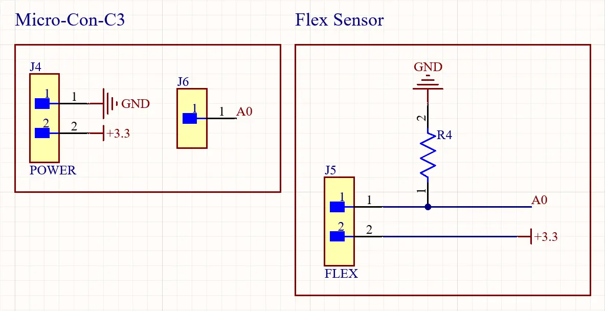
Hardware Design
This board acts as a simple voltage divider circuit, preparing the analog signal before it travels through the cables to the main ADC pin on my Week 8 board.
I incorporated a 470Ω fixed pull-down resistor to create the voltage divider circuit. This specific value was chosen because it roughly matches the base resistance of the carbon flex sensor when it is folded. By balancing the voltage divider with this 470Ω baseline, it ensures the microcontroller's ADC Analog-to-Digital Converter receives a sufficiently wide dynamic voltage range during the physical bend. If a much lower resistor were used, the initial voltage changes would be too minuscule to detect, whereas the 470Ω, provides a strong raw signal for the software's Gamma Correction to work with.
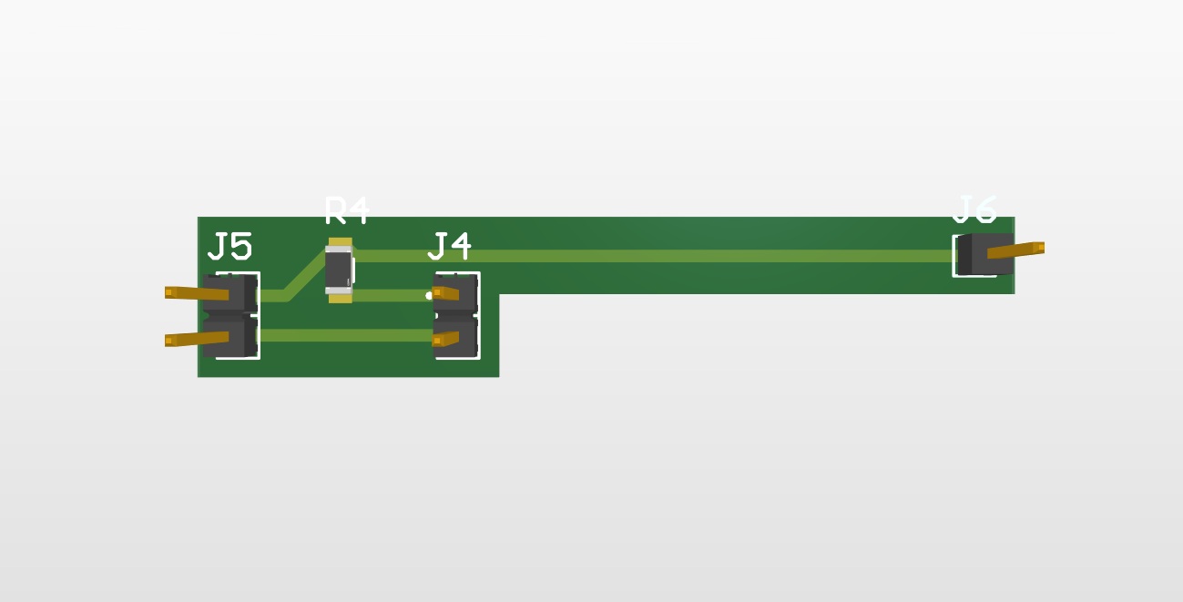
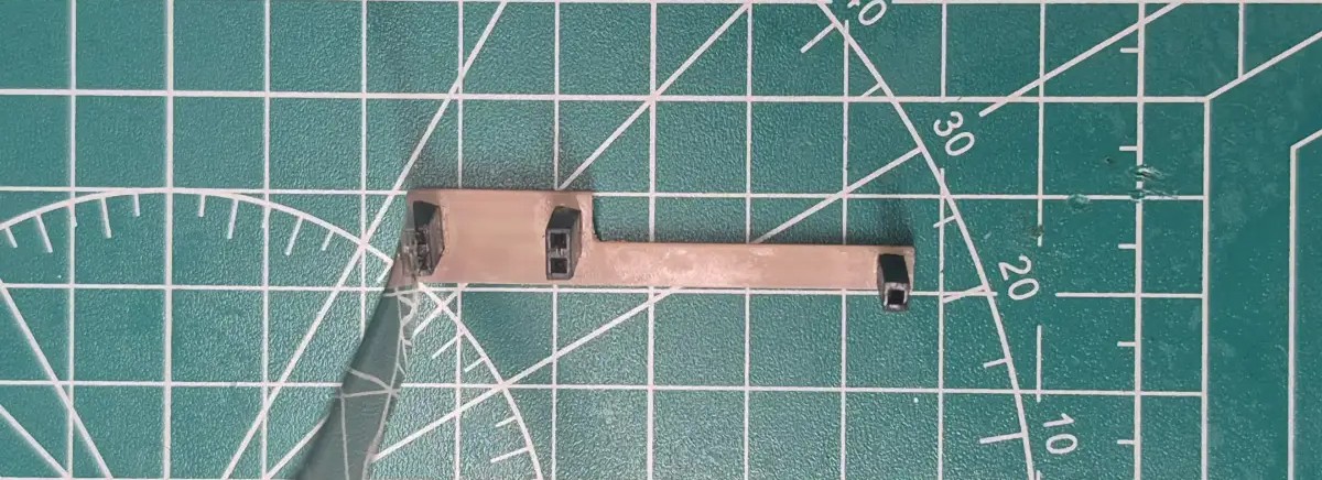
Modular Analog PCB