Outputs Devices
During the group assignment on output devices, we practiced measuring and analyzing the power consumption of various actuators, such as DC motors, servos, and LEDs. Using lab tools like multimeters, our team was able to track voltage and current consumption in real time under different loads. Calculating the total power dissipation P = V x I allowed us to physically see how different output devices stress a circuit, showing the importance of the track width of the PCBs we manufacture at the Fab Academy and why trusting only on the logic pins of a microcontroller for power is insufficient and harmful.
Additionally, this exercise deepened my knowledge of the hardware needed to safely control high-powered devices. I learned why driver circuits, such as specialized motor drivers, are essential components for bridging the gap between a low-current microcontroller and high output loads.
Group Assignment Week 10
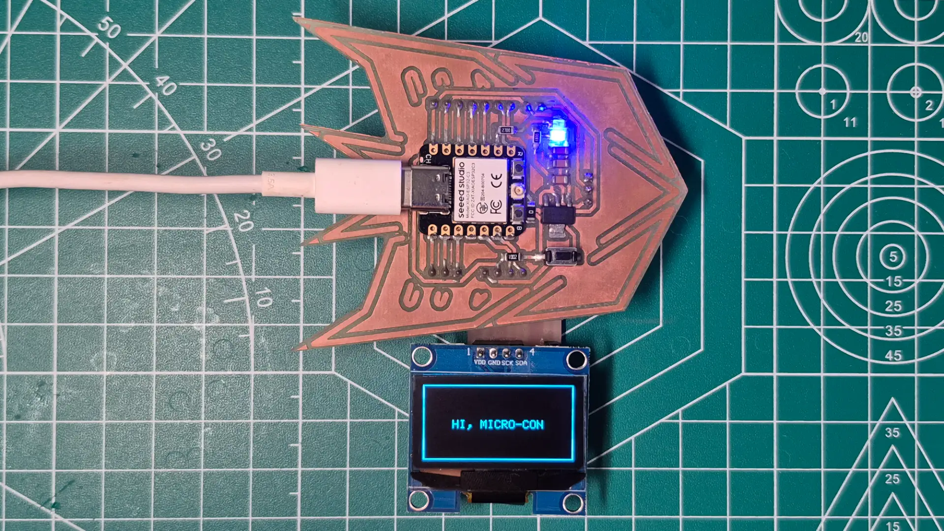
For this week's Output Devices assignment, my main focus was programming the logic to drive a display and control the movement of two servo motors. Specifically, the servo code is designed to move them in 45-degree increments until they reach the end of their travel, and then return them to their starting position. As for the display, the program successfully sends a custom text message directly from the XIAO microcontroller to be displayed on the screen.

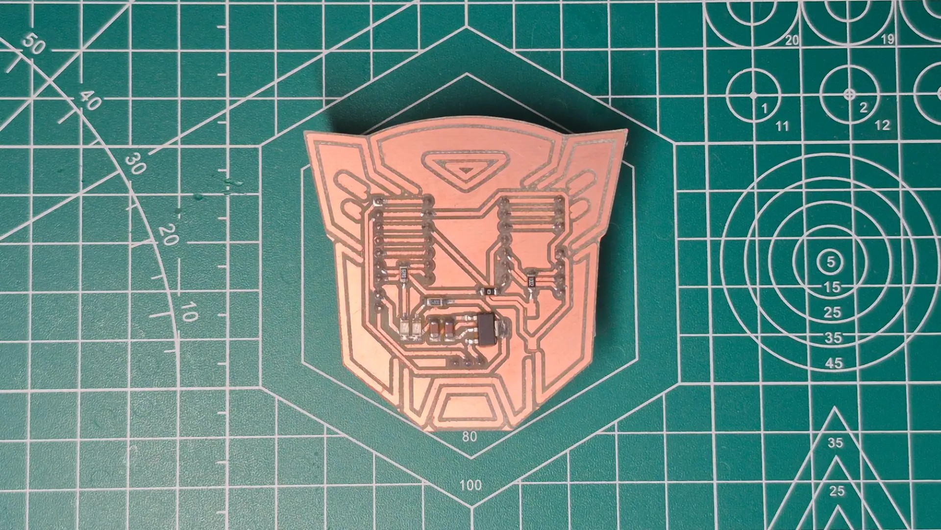
In addition, with next week dedicated to networking and communications, I designed and fabricated another PCB. For this new board, our instructor provided us with a Seeed Studio XIAO ESP32-C6. Given its wireless connectivity options, I'm confident the ESP32-C6 will be an excellent choice for testing wireless networking capabilities next week.
Programming and Testing Outputs
Display
Servo Motors
#include <Arduino.h>
#include <Wire.h>
#include <Adafruit_GFX.h>
#include <Adafruit_SH110X.h>
#include <SPI.h>

#define i2c_Address 0x3c
#define SCREEN_WIDTH 128
#define SCREEN_HEIGHT 64
#define OLED_RESET -1

Adafruit_SH1106G display = Adafruit_SH1106G(SCREEN_WIDTH,
SCREEN_HEIGHT, &Wire, OLED_RESET);

void setup() {
  Serial.begin(115200);
  delay(200);

  if(!display.begin(i2c_Address, true)) {
    Serial.println("Fail to initialize OLED SH110X");
    for(;;);
  }

  display.clearDisplay();
  display.drawRect(0, 0, SCREEN_WIDTH,
  SCREEN_HEIGHT, SH110X_WHITE);
  display.setTextSize(1);
  display.setTextColor(SH110X_WHITE);
  display.setCursor(25, 30);
  display.println("HI, MICRO-CON");
  display.display();
}

void loop() {
}
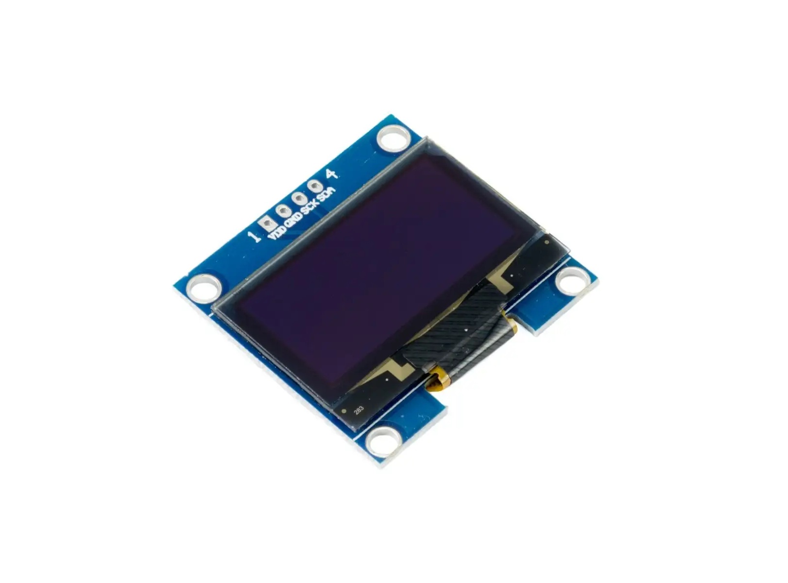
The OLED display is a high-contrast visual output device. Instead of controlling individual light-emitting diodes directly, the code utilizes the I2C protocol to communicate with the internal SH1106 display driver, manipulating a matrix of pixels through a dedicated memory buffer.
Libraries and Definitions
#include <Adafruit_GFX.h>and#include <Adafruit_SH110X.h>: Libraries developed by Adafruit. The GFX library provides the core graphics engine for calculating shapes and text, while the SH110X library handles the low-level hardware commands specific to the screen's internal controller.- The
#include <SPI.h>library handles the Serial Peripheral Interface protocol. Although my specific OLED uses I2C, this library is often included as a foundational dependency for the Adafruit GFX engine to compile properly. Adafruit_SH1106G display = ...: Instantiates the main display object. It links the physical screen dimensions, the I2C communication bus (&Wire), and the reset pin configuration into a single, manageable software interface.
Variables Configuration and Memory Allocation
#define i2c_Address 0x3c: The explicit hexadecimal address of the display on the I2C bus. This is mandatory for the microcontroller to direct its data packets to the correct peripheral device without causing bus collisions.#define SCREEN_WIDTH 128and#define SCREEN_HEIGHT 64: Defines the absolute pixel matrix boundaries. These constants ensure the microcontroller allocates the precise amount of internal RAM needed for the display buffer (1024 bytes).#define OLED_RESET -1: Informs the library that this specific OLED module does not utilize a dedicated hardware reset pin, effectively saving a valuable GPIO pin on the XIAO microcontroller for other inputs or outputs.
Hardware Setup and Configuration
delay(200);: A brief but critical pause in the boot sequence. It allows the OLED's internal capacitors to fully charge and the controller to power up before the microcontroller attempts any I2C communication.display.begin(i2c_Address, true): Wakes up the screen on the I2C bus and verifies the physical connection. If the hardware fails to acknowledge the initialization packet, the program deliberately halts itself in an infinite loop (for(;;);) to prevent further execution and visual rendering errors.
Graphics Processing
- Clear Memory:
display.clearDisplay()erases the previous data from the microcontroller's internal RAM buffer, providing a blank slate, but does not yet clear the physical screen. - Draw Geometries:
display.drawRect(...)calculates the mathematical coordinates to plot a boundary box into the memory buffer, verifying the outer limits of the 128x64 matrix to ensure no dead pixels exist on the edges. - Typography Setup:
display.setTextSize(1)anddisplay.setCursor(25, 30)configure the rendering parameters for the built-in font engine, mapping exactly where the first pixel of the text should start. - Memory Transfer:
display.display()acts as the final trigger. It takes the entire compiled visual frame from the XIAO's internal RAM and pushes it over the I2C bus to the OLED panel in a single, rapid data burst.
Hardware Design
OLED Data Sheet
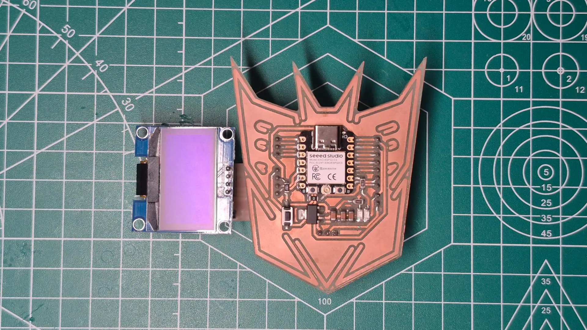
For this Output Devices task, I took advantage of the modularity of the I2C communication protocol by reusing the custom expansion board I designed and fabricated last week for my input sensor. Since both the gyroscope and the OLED display share the same 4-pin hardware architecture VCC, GND, SDA, and SCL
Inputs Devices
Fortunately, the OLED display includes its own internal 10kΩ pull-up resistors soldered directly to the SDA and SCL traces. Had I included redundant resistors on my custom PCB, placing them in parallel would have drastically reduced the equivalent resistance.
Final Result
#include <Arduino.h>
#include <ESP32Servo.h>

Servo Servo_1;
Servo Servo_2;

const int Pin_Servo_1 = 18;
const int Pin_Servo_2 = 20;

void setup() {
  Servo_1.attach(Pin_Servo_1, 500, 2400);
  Servo_2.attach(Pin_Servo_2, 500, 2400);

  Servo_1.write(0);
  Servo_2.write(0);
  delay(1000);
}

void loop() {
  for (int Angle = 0; Angle <= 180; Angle += 45) {
    Servo_1.write(Angle);
    Servo_2.write(Angle);
    delay(1000);
  }

  delay(1000);

  Servo_1.write(0);
  Servo_2.write(0);
  delay(1000);
}
Servomotors are electromechanical actuators that rely on precise Pulse Width Modulation or PWM signals to determine their absolute angular position. The microcontroller must generate a highly stable square wave where the width of the high pulse directly dictates the target angle of the mechanical arm.
Libraries and Definitions
#include <ESP32Servo.h>: A specialized library crucial for ESP32 chips. The standard ArduinoServo.hlibrary is written for AVR microcontrollers and fails on the ESP32. This specific library bridges the gap, utilizing the ESP32's native LED Control peripheral to generate hardware-backed, no fluctuations PWM signals.Servo Servo_1;andServo Servo_2;: Instantiates the software objects. These objects will independently manage the internal timer channels and calculate the necessary duty cycles for each physical motor.const int Pin_Servo_1 = 18;: Explicitly maps the software control objects to specific General-Purpose Input/Output or GPIO pins on the microcontroller board.
Hardware Setup and Configuration
Servo_1.attach(Pin_Servo_1, 500, 2400): This is a critical initialization parameter. While legacy servos often operated on a 1000µs to 2000µs pulse range, many modern micro-servos require a wider frequency band to achieve a true 180-degree sweep. By manually hardcoding the minimum 500µs for 0° and maximum 2400µs for 180° pulse widths, the code ensures full range of motion while preventing the motor from grinding against its physical end-stops, which could cause a high-current stall.Servo_1.write(0): Sends an initial baseline command during the boot sequence, forcing the physical gears to home to their true zero position before any dynamic actuation begins.
Actuation Logic
- The Bounded Loop:
for (int angulo = 0; angulo <= 180; angulo += 45)establishes the movement parameters. It creates a controlled sequence starting at 0, strictly incrementing by 45-degree intervals, and safely terminating precisely at the 180-degree mechanical limit. - Hardware Update:
Servo_1.write(angulo)dynamically translates the current integer angle into the correct PWM duty cycle and immediately updates the microcontroller's hardware timer to alter the electrical signal. - Mechanical Synchronization:
delay(1000)introduces a mandatory 1-second blocking pause. Because the microcontroller processes code in microseconds while physical gears require milliseconds to physically move, this delay prevents the software from outrunning the hardware.
Hardware Design
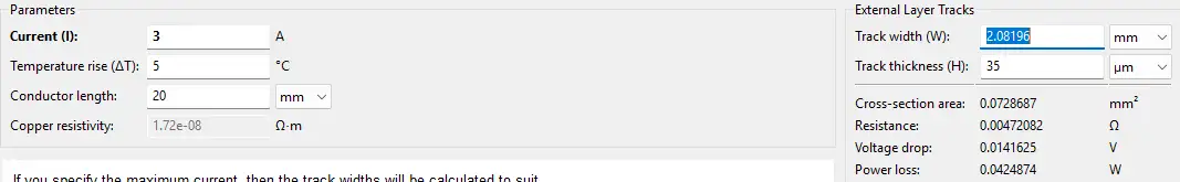
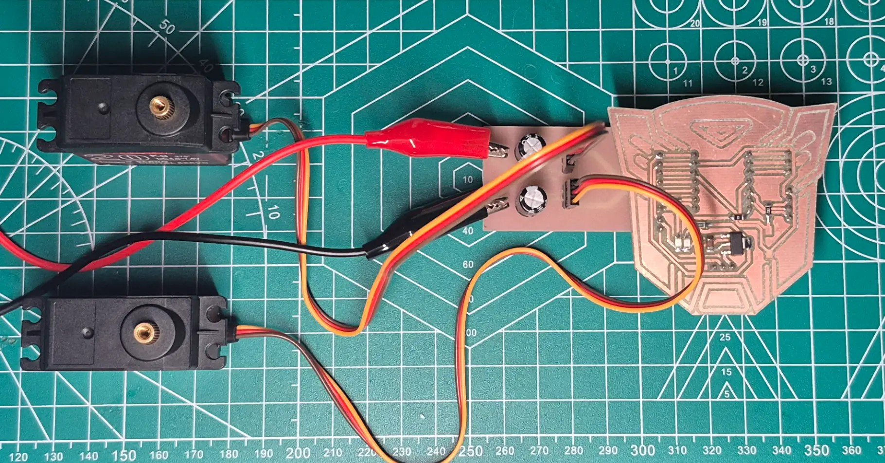
Servomotors draw significant current, especially under mechanical load, so powering them directly from the microcontroller's fragile internal bus is a serious design flaw. To address this, I designed a dedicated, modular PCB for power distribution, which safely isolates the high-current 5V external power supply from the delicate 3.3V logic of the XIAO ESP32-C6. To ensure the board could handle the electrical load without overheating, I used the KiCad PCB Calculator tool to accurately determine the optimal width of the power traces, based on the anticipated maximum current draw. Additionally, designing a large common ground plane was crucial. By physically connecting the external 5V ground to the XIAO's ground, the system establishes a shared 0V reference point, without which the servomotors would be unable to accurately read the PWM control signals.
Power Consumption Calculation
To ensure my custom board and power supply can handle the load, I calculated the power requirements for my output devices.
Based on the component's datasheet:
Servo Data Sheet
- Operating Voltage (V): 5.0 V
- Stall Current (I): 1.5 A per servo
Using the power formula P = V × I:
- Power per servo = 5.0 V × 1.5 A = 7.5 W
- Total Power for 2 servos = 7.5 W × 2 = 15.0 W
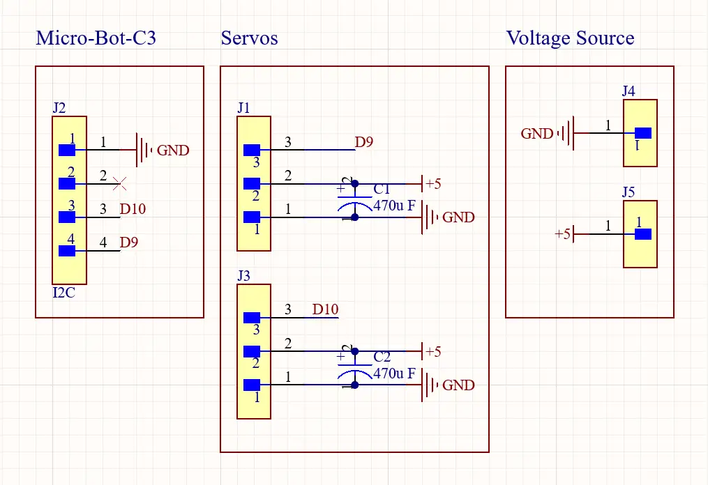
To prevent current spikes when the servo motors start from causing voltage drops and resetting the board, I integrated two 470 µF electrolytic capacitors next to the connectors. These act as local, fast-acting power reserves; when the motor demands a sudden surge, the capacitor discharges instantly, keeping the 5V bus stable and protecting the communication lines from inductive noise.
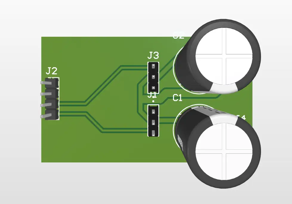
Modular Servo PCB
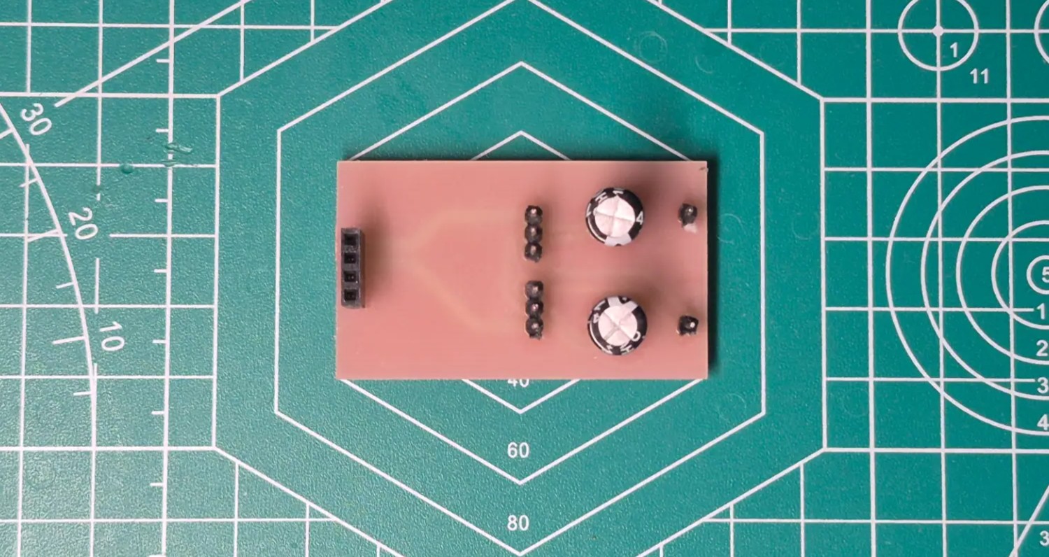
Final Result
Hardware Discovery the PWM Mapping
During the physical testing phase, I observed an interesting discrepancy between the software and the hardware,
although my code's for loop was explicitly written to sweep from 0 to 180 degrees, the physical
motors were actually completing a full 270-degree rotation. This happens because the servo.write(angle)
function does not send actual degrees to the motor; it sends a mapped PWM pulse width.
The ESP32Servo library defaults to a 180-degree mathematical map. When the loop reaches
servo.write(180), the microcontroller outputs the maximum defined pulse width of 2400µs.
However, the physical servos I sourced are geared for 270 degrees. Their internal hardware interprets a 2400µs
pulse not as 180 degrees, but as the command to reach their absolute maximum mechanical limit 270°. Therefore, my
software increments of 45 degrees were actually commanding the motor to move in 25% increments of its total available
range, approximately 67.5 physical degrees per step.