

Week 15
System Integration
// MAIN OBJECTIVE \\
Design and document the system integration for your final project.
Week Description
This week I will be covering everything I learned regarding the design and implementation of the system for my final project. This includes everything related to the PCB design, the 3D design of the enclosure, and how I will organize the electronic components and wiring.
System Architecture
To ensure all subsystems work together seamlessly, I designed the master PCB. Taking into account every component, the traces and the pinout were designed. I needed to include I2C communication, an LED indicator, 4 ADC outputs for the brushless motors, a button, and a buzzer. For power, I added several pins with 5V inputs and outputs, 3.3V outputs, and plenty of GND pins because every brushless motor needs one.
If you want to see in more detail how I made this PCB, check out my Electronics Production Week →.
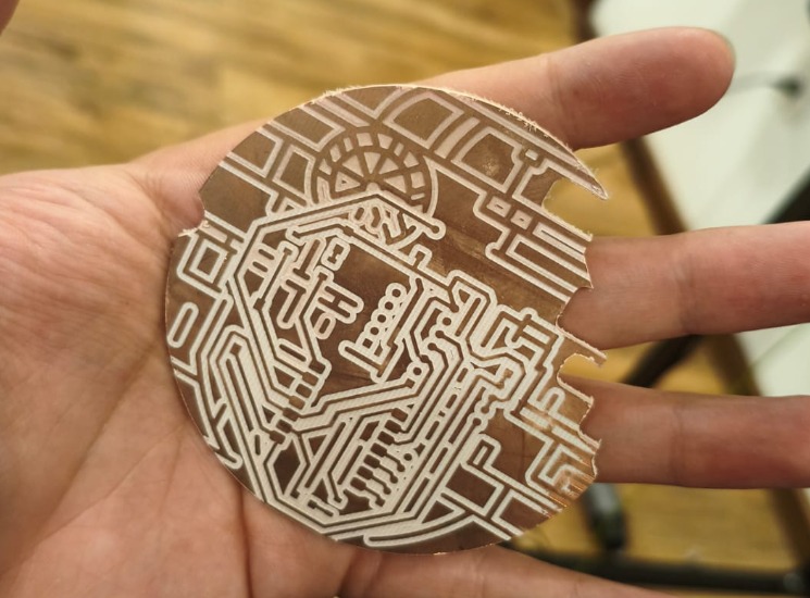
Milled Death Star PCB.
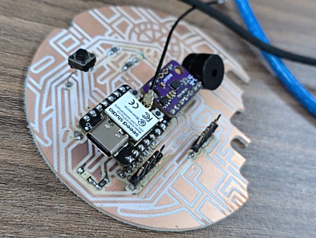
Soldered Death Star PCB.
Physical Packaging
One of the most critical parts of system integration is ensuring that the electronic components fit securely inside the fabricated enclosure without interfering with moving parts or causing short circuits.
Tolerance Review
I designed specific mounting standoffs in the 3D enclosure for the custom PCB and the brushless motors. Managing wire routing was essential, so I created a chamber to keep cables away from active mechanisms.
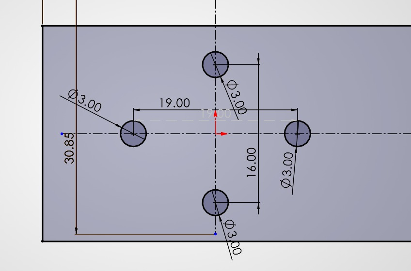
Tolerance test for the brushless motors.
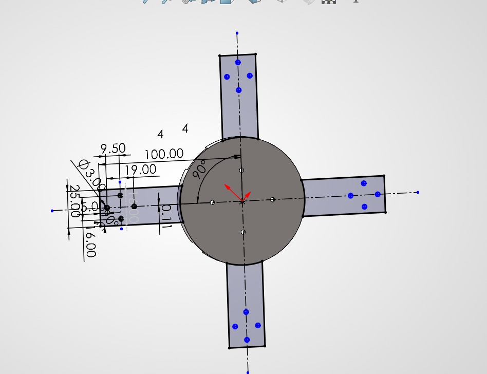
Tolerances and design for the brushless motors and the PCB.
Wire Location and Assembly
After checking all the tolerances and designing the enclosure, I needed to route the wiring correctly and secure it in place. Here are all the wiring locations on the enclosure:
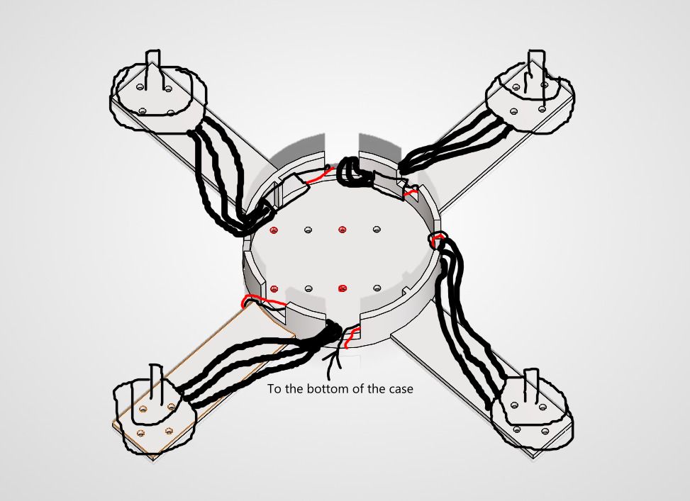
Exterior wiring.
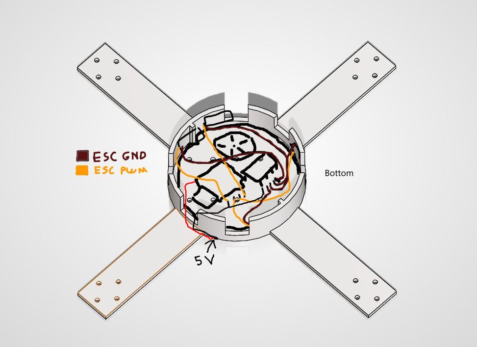
Middle wiring.
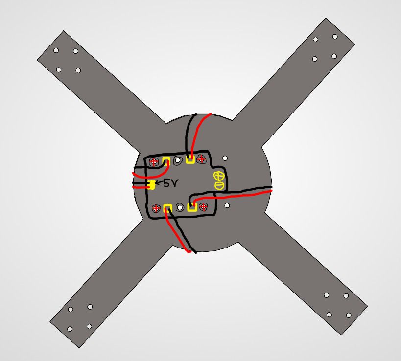
Bottom wiring.
Communication & Software Integration
The integration here involves merging the sensor reading code from the Inputs week with the PID control code, ensuring that FreeRTOS tasks do not block each other, and verifying that the data payload perfectly matches what the interface expects to receive and parse. I will approach this topic in my Wildcard week→, where I will make a professional PID control system.
Power Management
One of the big problems when making homemade drones is power management. This is because of the type of drone I'm making: a speed drone that needs powerful brushless motors capable of lifting the drone easily and quickly. The problem with this is that I need a battery capable of deploying a decent amount of voltage and a ton of current in a short period of time (discharge rate). Therefore, I needed to buy a 4S LiPo battery with a high discharge rate and a decent amount of capacity (1300 mAh).
Each brushless motor I'm using can draw a maximum of 30A for the initial thrust, which multiplied by 4 gives us 120A for a strong lift. I bought a 4S 14.8V 1300mAh 120C battery. Let's do some calculations: to know the exact amps of discharge the battery can provide, we need to multiply the C value by the capacity in Amps (1.3A). The result of 120 * 1.3 gives us a total of... 156 amps continuously! That is more than enough current for the drone to work properly. But now, here is another problem.
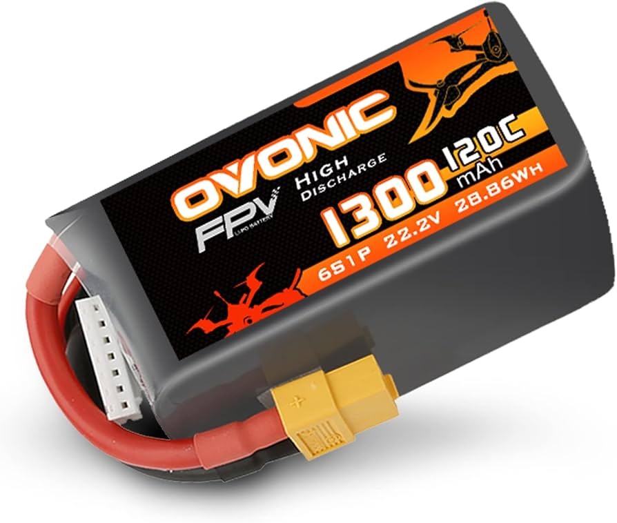
The high discharge battery that I bought.
The most important problem of all was simple to detect but complicated to solve: power delivery to the XIAO ESP32-C6. I needed to supply the microcontroller with 5V. At first, I thought about a voltage divider, but I was worried about the amount of variable current I would be handling. It would certainly get very hot, and the electronic noise could cause power loss in the microcontroller. So, I decided to buy a BEC (Battery Eliminator Circuit). With this, I can easily manage all the power needed for my brushless motors and my XIAO simultaneously.
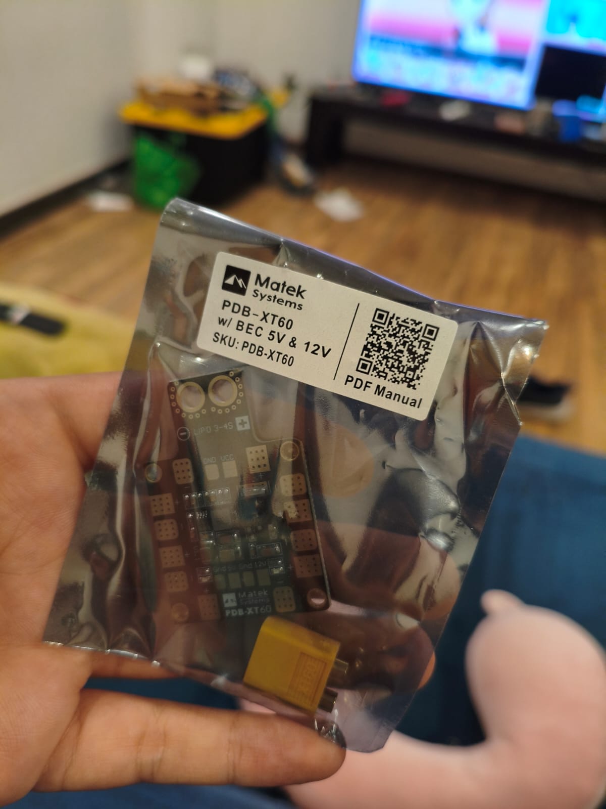
The BEC I'm using.
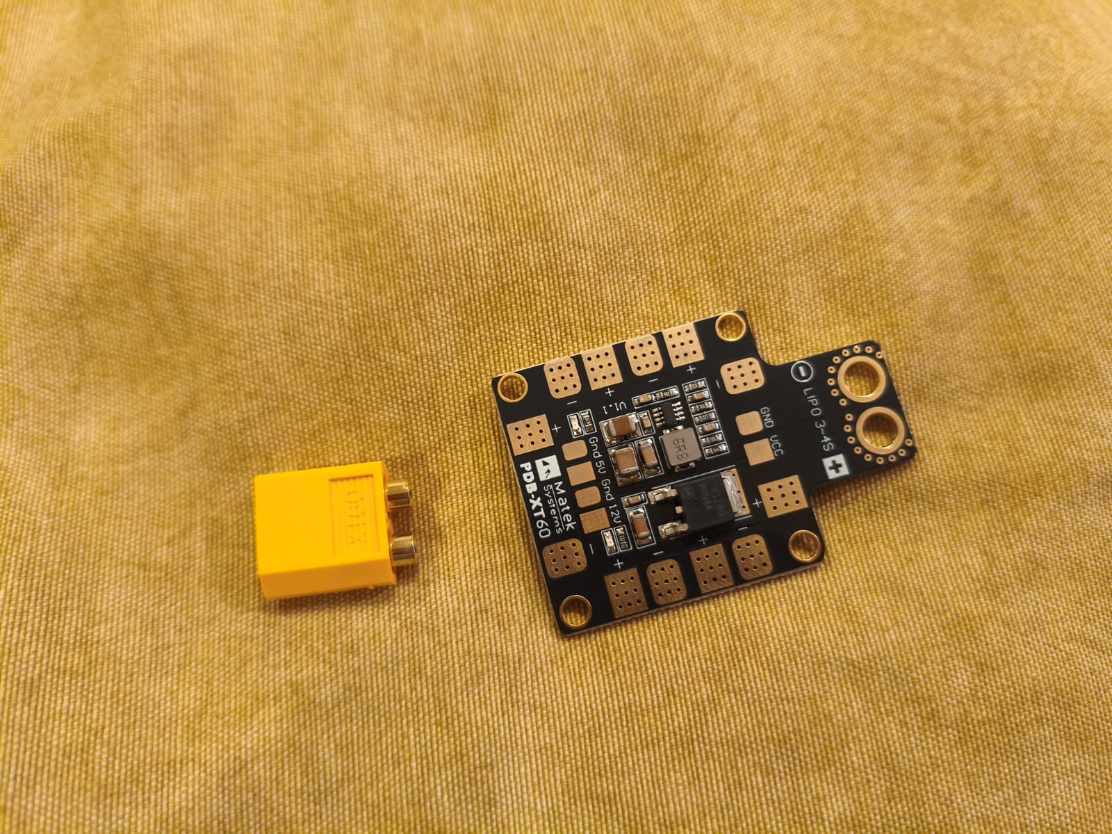
BEC pinout.
Conclusion
This is a great step for my final project. Combining all these minute details to make a high-quality product, along with the knowledge from previous weeks, will enable me to do an excellent job on the final project, here you can go to the Final Project Page.