

Fab Academy 2026
Final Project
Drone code: H.E.R.M.E.S
AI generated sketch for visual purposes
Slide and Edited Video
In this part is the promotional slide and video that shows in a picture and a minute the most important stuff of the project such as what does the project do, the creation of the parts, the programming, and other skills that I had learn in the FABACADMY course.
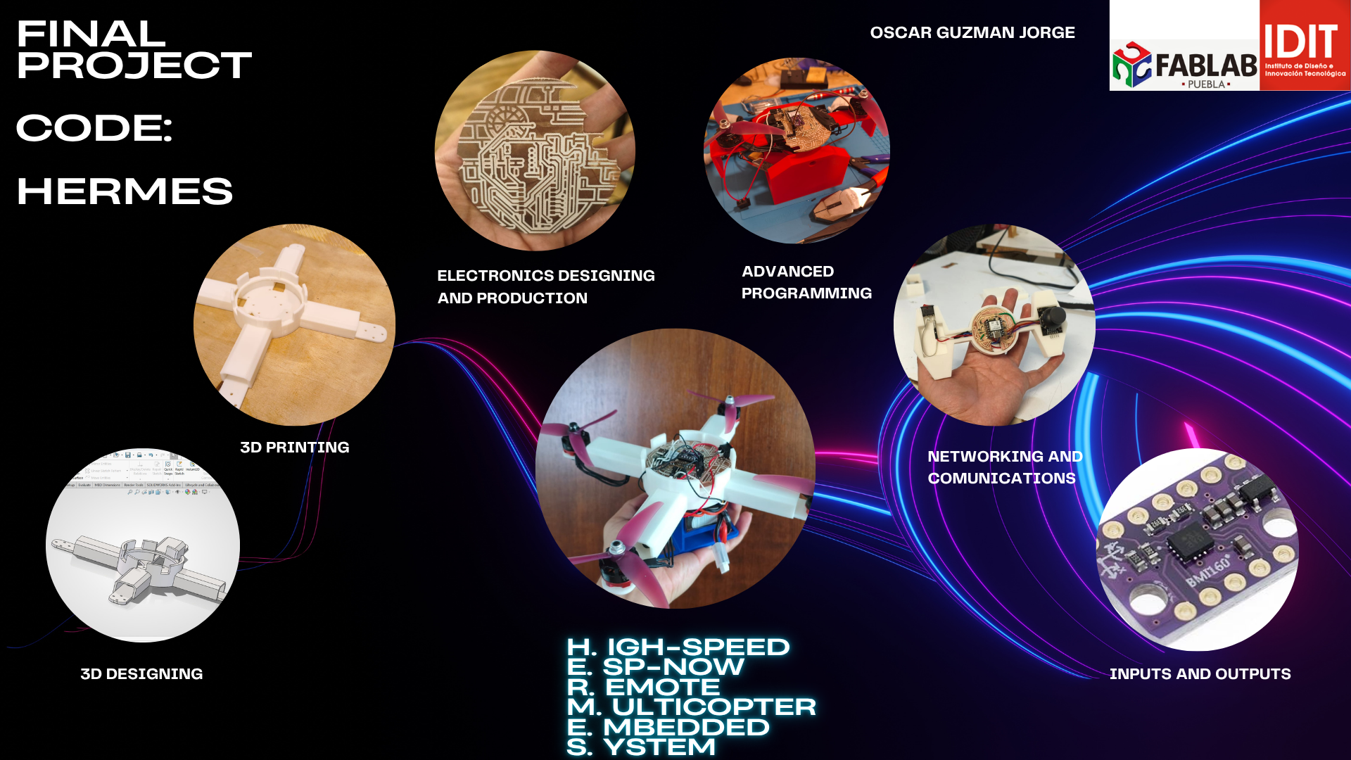
H.E.R.M.E.S. Slide.
Project Idea
My final project consists of a radio-controlled Drone vehicle built from scratch. It merges the physics of a drone with the agility of radio controlled waves (hopefully with a remote control). The propeller-powered brushless motors are mounted on a tilting mechanism (thrust vectoring), allowing the vehicle to do air movement.
The system is powered by an ESP32-C6 and controlled via custom-made control plate (With another ESP32-C6), providing a more intuitive pilot interface.
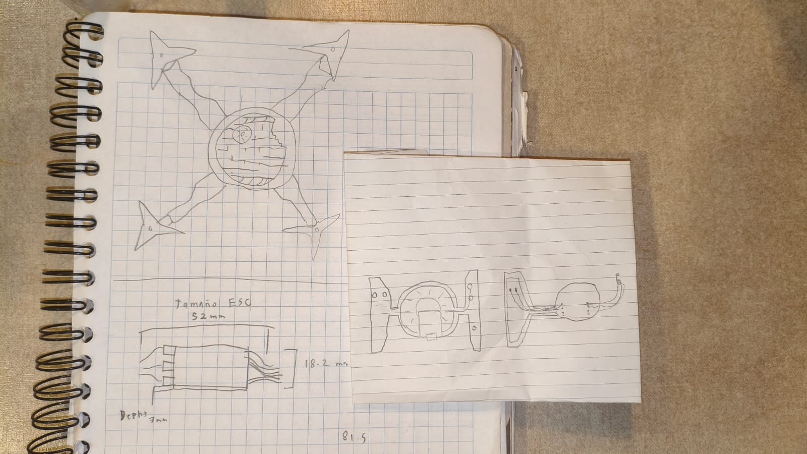
Initial Prototype Sketch
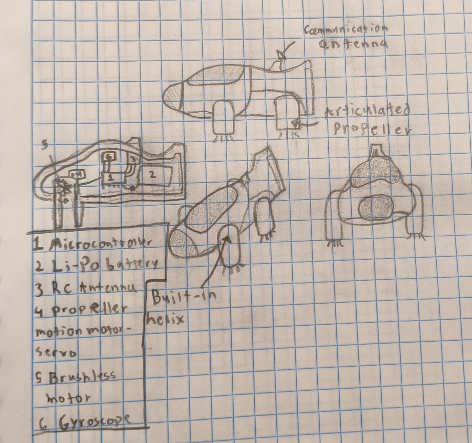
After various ideas, I made the first sketch of the prototype, detailing the propeller placement and the integration of the 3D-printed chassis.
Challenges
Building a vehicle from zero involves complex challenges in programming for stabilization, 3D design for mechanical endurance and post-processing. I am documenting every iteration, failure, and improvement in my repository to showcase the engineering cycle. Key challenges include:
- Obtaining the electronics and materials.
- Managing the center of gravity for stabilization in the air.
- Latency reduction between the controller and the drone.
- Power efficiency with heavy LiPo batteries.
"The goal is not just to build a flying machine, but to master the integration of 3D manufacturing, embedded systems and wireless control."
Project development
To start the making of the final project first of all I need to think, design and make a lot of things, and I'll be applying all the knowledge we have been learning throughout the course. I will be detailing everything later.
First Accurate Sketches
Once I started making the PCB (more details below), I drew a few sketches of the final drone according to my idea. I know that these aren't high-quality sketches but that's not my strong suit.
First real sketches of the final project.
Explaining the Name: H.E.R.M.E.S.
Before diving into the schedule and technical planning, it is important to explain the inspiration behind the name H.E.R.M.E.S. I named the drone after the ancient Greek messenger god, who was renowned for his unmatched speed and ability to travel seamlessly between worlds. I chose this name as a direct analogy for the core of the drone's communication system and what it does. By utilizing the ESP-NOW wireless protocol, the drone achieves blazing-fast, extremely low-latency communication between the custom remote control and the flight controller making it fly swiftly in the air, mirroring the swift and reliable delivery of messages by Hermes himself.
Also, the acronym for H.E.R.M.E.S. is High-speed ESP-NOW Remote Multicopter with Embedded Systems, so it fits perfectly.
Mid-Term Review: Project Schedule
For the Mid-Term review, I designed a comprehensive project schedule. Creating this timeline is crucial because it helps track technical dependencies and ensures that manufacturing bottlenecks do not halt the software development. A well-structured schedule allows me to visualize the milestones needed to complete H.E.R.M.E.S. successfully.
| Timeline | Task Distribution | Related Week / Skills |
|---|---|---|
| Week 1 | Hardware Foundation: PCB Designing, Milling, and 3D Design. *Note: 3D printing runs in parallel with the PCB routing, as the printer can operate autonomously without requiring my full attention. |
Electronics Production & Computer-Aided Design |
| Week 2 | Assembly & Debugging: Putting together the drone frame, mounting the electronics, and making initial error corrections (bug fixing). | System Integration |
| Week 3 | Remote Control: Creation of the custom RC controller interface. | Input Devices |
| Week 4 | Flight Software: Programming the PID control system for axis stabilization. | Embedded Programming |
| Week 5 | Wireless Link: Implementation of the low-latency ESP-NOW communication protocol. | Networking and Communications |
System Implementation & Finalization
According to the schedule, immediately after finishing the communication protocols, a strict timeframe of 3 days is dedicated exclusively to the Implementation of Everything. This phase is where the RC inputs, the ESP-NOW link, and the PID flight controller are merged into one cohesive system. Finally, the last step is the Project Finalization, which involves the final tuning, flight tests, and wrapping up this repository documentation.
PCB designing
This is the first thing I started to do, checking all the electronic components that I needed to use. After a deep research comparing a lot of components and prices, I was left with the following:
| Qty | Description | Price (USD) | Category |
|---|---|---|---|
| 1 | Microcontroller ESP32-C6 | $ 18.00 | Electronics |
| 4 | Brushless Motors Rs2205 + ESCs | $ 90.00 | Propulsion |
| 1 | BMI-160 Gyroscope | $ 6.00 | Sensors |
| 1 | 4S LiPo Battery (14.8V) | $ 25.00 | Power |
| 1 | Energy Regulator and ESC holder | $ 10.00 | Power |
| 1 | Sunulu PLA filament coil | $ 20.00 | Structure |
| - | Total | $ 169.00 | Investment |
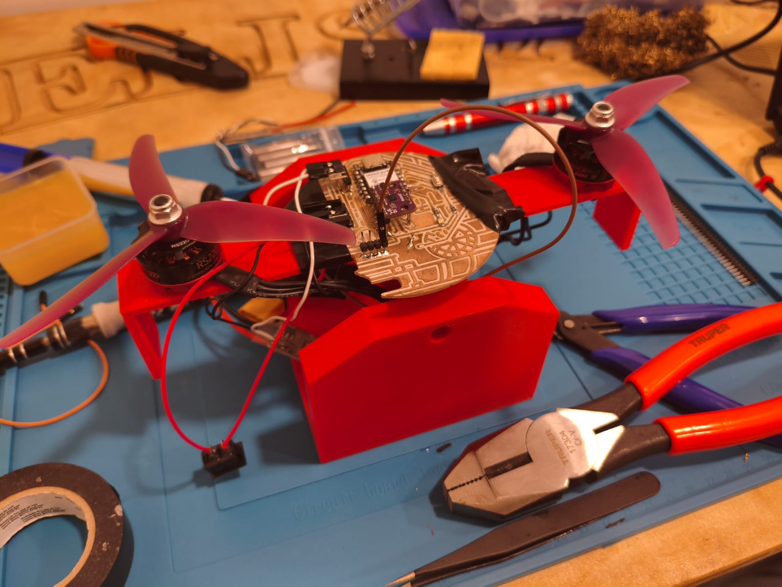
After buying every component, I started making the master PCB, and taking into account every component, the traces and the PINOUT were designed. I needed to put I2C communication for the BMI-160, a LED indicator, 4 ADC outputs for the brushless motors, a button, and a buzzer. For power, I added several pins with 5V inputs and outputs, 3.3V outputs, and a lot of GNDs.
If you want to check out with more detail how I made this PCB, go check out my Electronics Production Week →
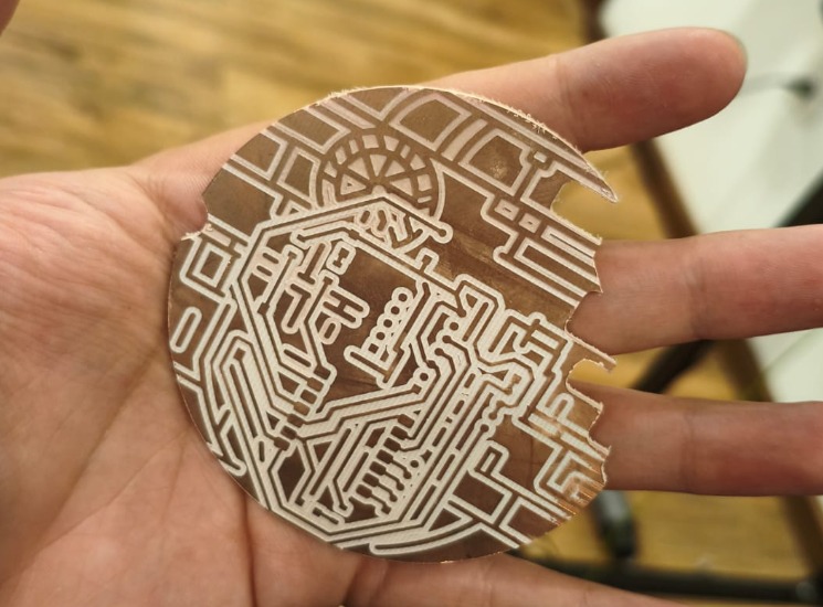
Milled Death Star PCB.
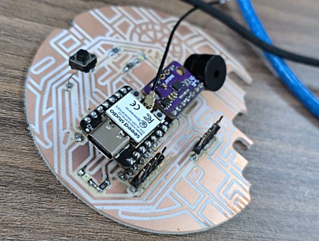
Soldered Death Star PCB.
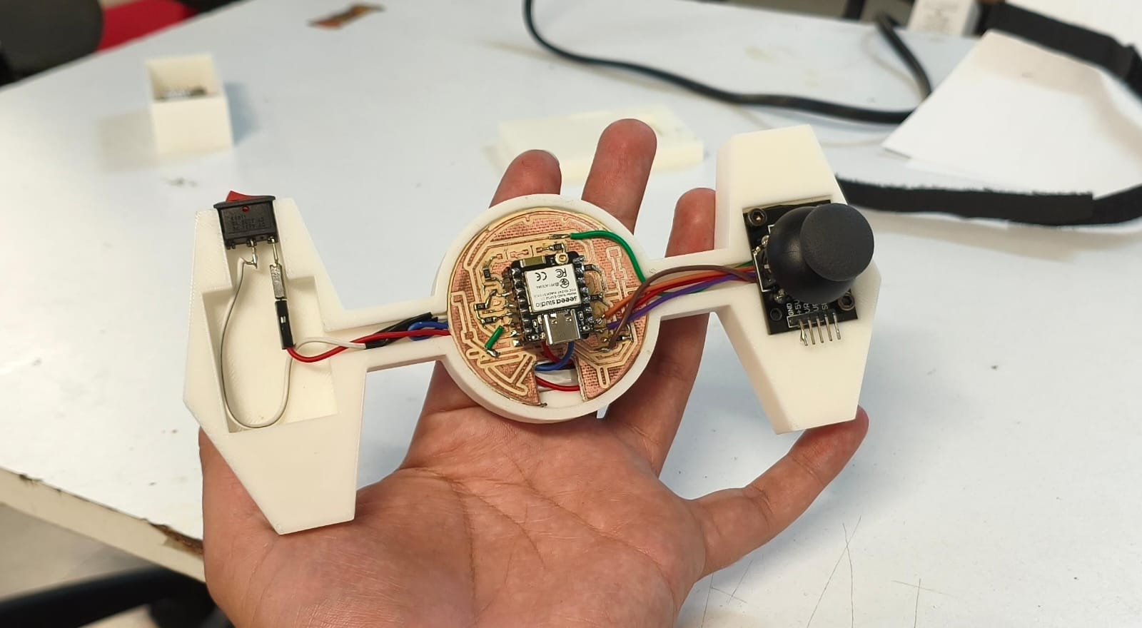
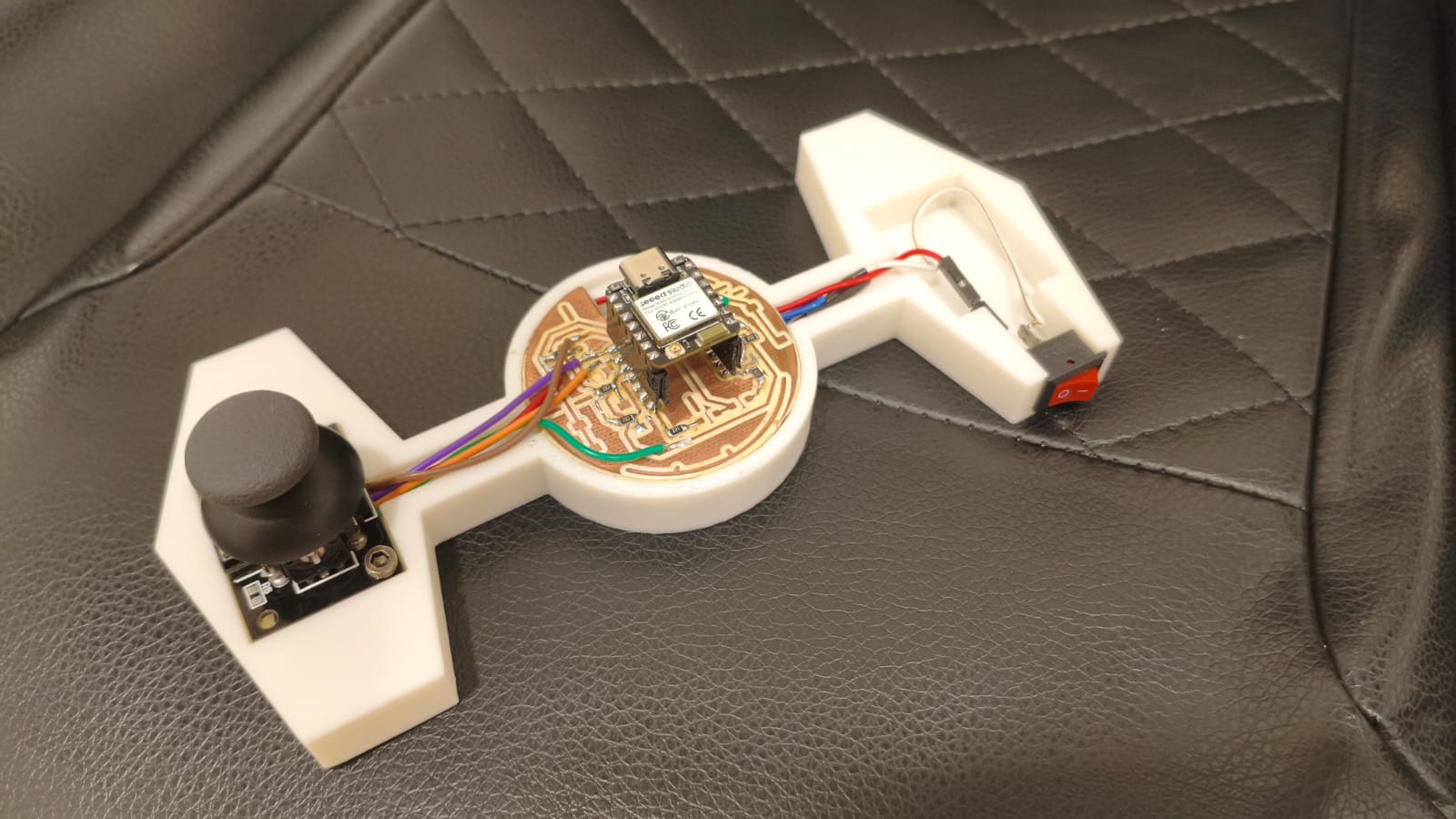
RC PCB
This is similar to the master PCB, but this one is a lot easier to make. With the knowledge of the Electronics Production Week, I made this RC controller that consists of a XIAO ESP32-C6, a Joystick, buttons, LEDs, and Resistors.
Because I wanted it to have the same theme as the Death Star PCB, I tried to make a circular shaped PCB (it is going to be in a Tie Fighter case):
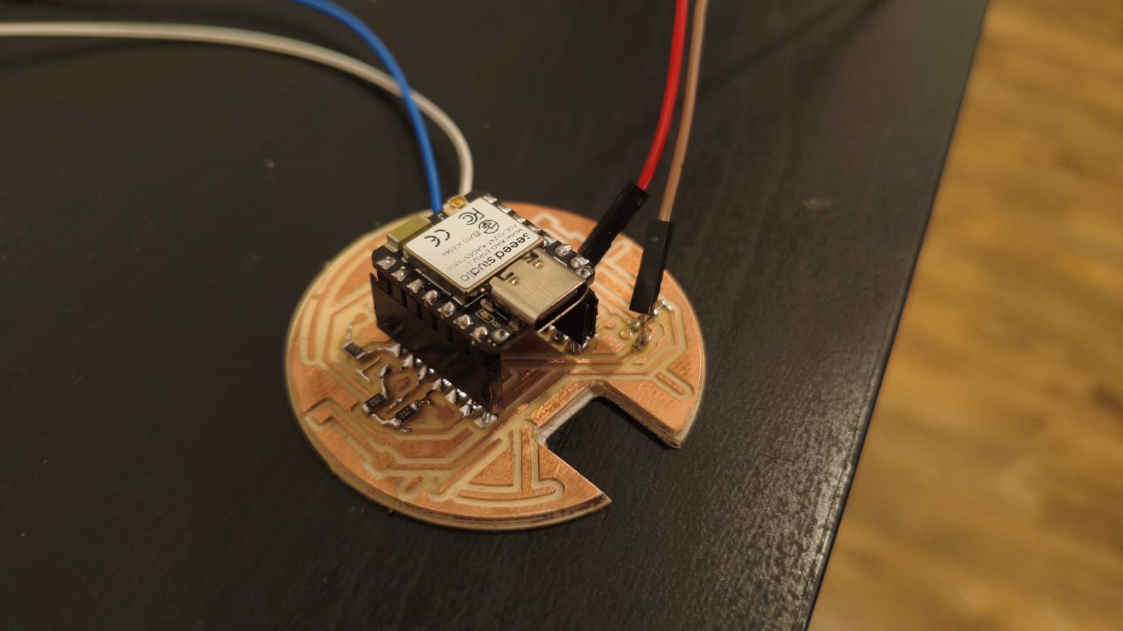
Soldered Tie Fighter PCB.
Drone Case Designing
Once I had the measurements of my PCBs, I started to design the casings and 3D printed structures for making the drone and the RC controllers. SOLIDWORKS was the software I used for designing all the 3D models, but before that:
Casing Implications and System Integrations
In order to make a good quality case, I needed to think about the wiring placement and tolerances, and I formulated a plan for making everything fit properly.
If you want to know more about the Integration of all the final project components, you can check my System Integration Week →
3D printing
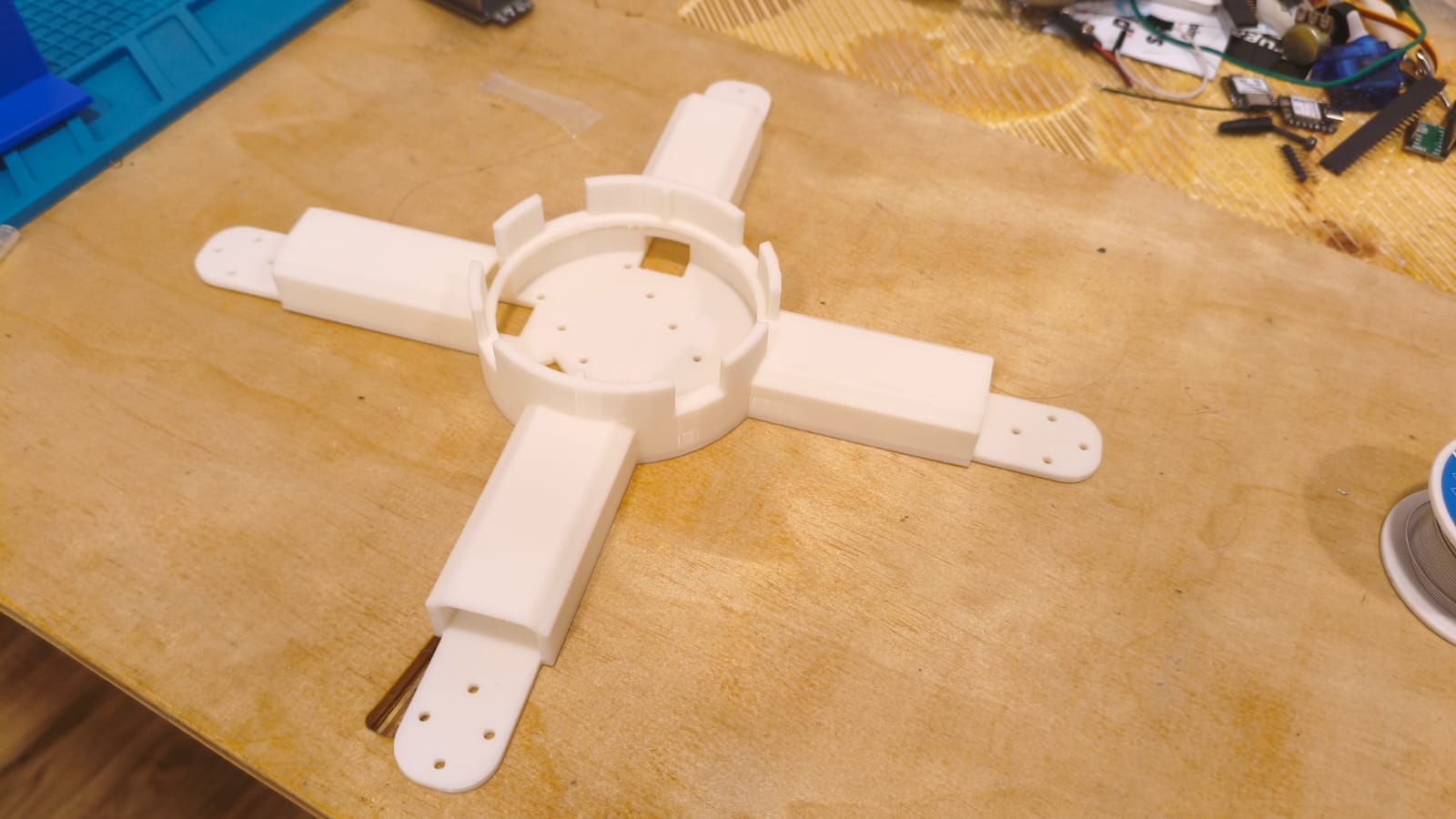
After designing and updating every part, I started the 3D printing process. It was a little bit slow because I ended up correcting the same part 5 times, but the result is pretty good.
3D printed parts of the drone chassis and battery.
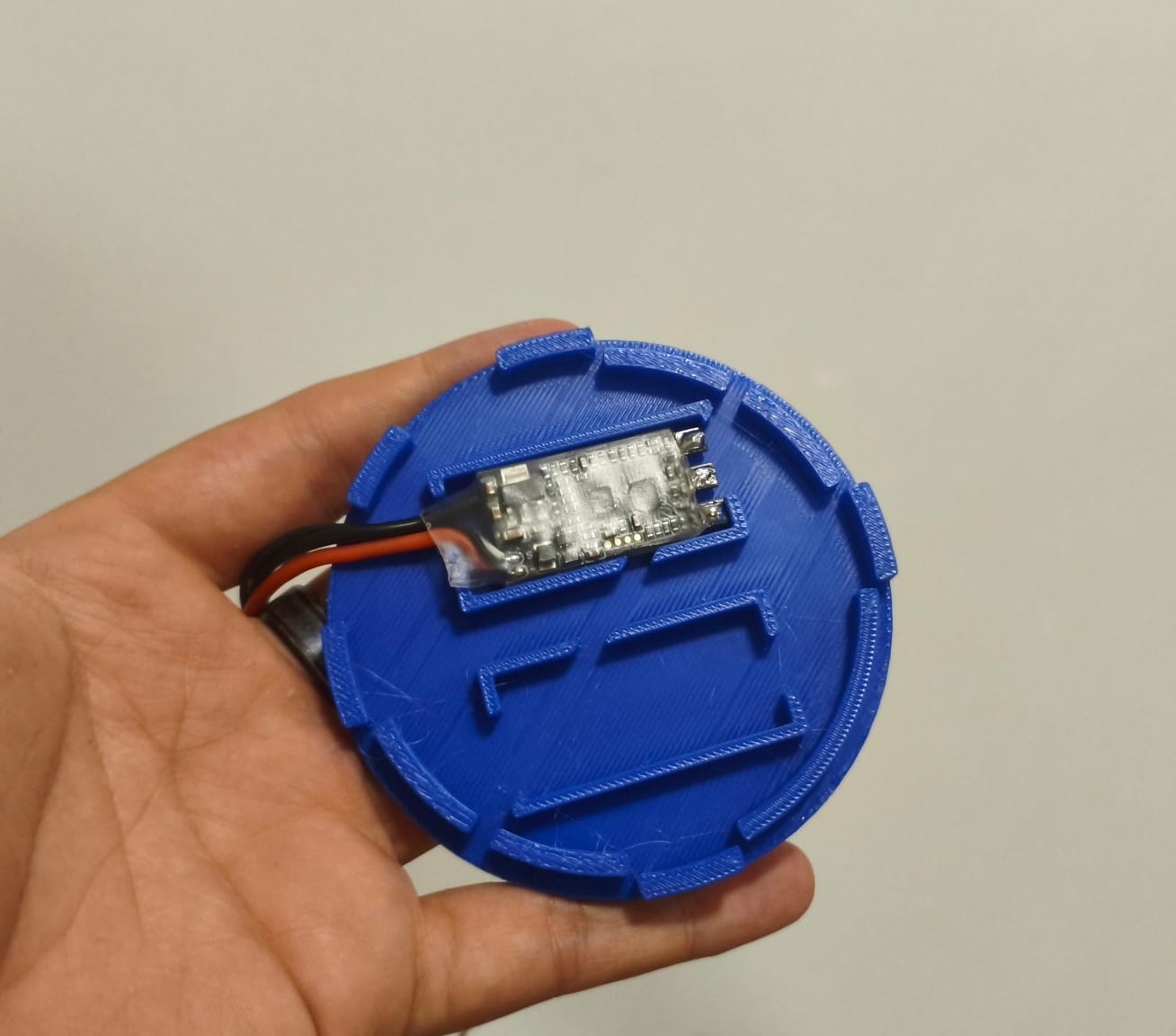
Custom top cover designed to hold the ESCs.
First mistakes
After printing all the parts and trying to assemble the first prototype, I encountered a few problems.
The first one was the ESC placing and wiring. Because I designed the top cover with space for 2 ESCs, the other two were getting in the way, so I had in mind changing the wiring distribution.
After taking the first problem into account, I printed all the parts I needed to assemble everything, but then something bad happened. The first prototype was useful and resistant for basic testing, but in actual practice, it was a little bit flexible and weak (SPOILER ALERT: It broke when it received an impact haha).
Drone Assembly
Once I printed the first prototype parts, I put it all together with screws and duct tape to start testing everything:
First prototype assembly.
After assembling the first prototype I started to do tests, but during these tests is where it fell off the table and broke.
The first prototype broken.
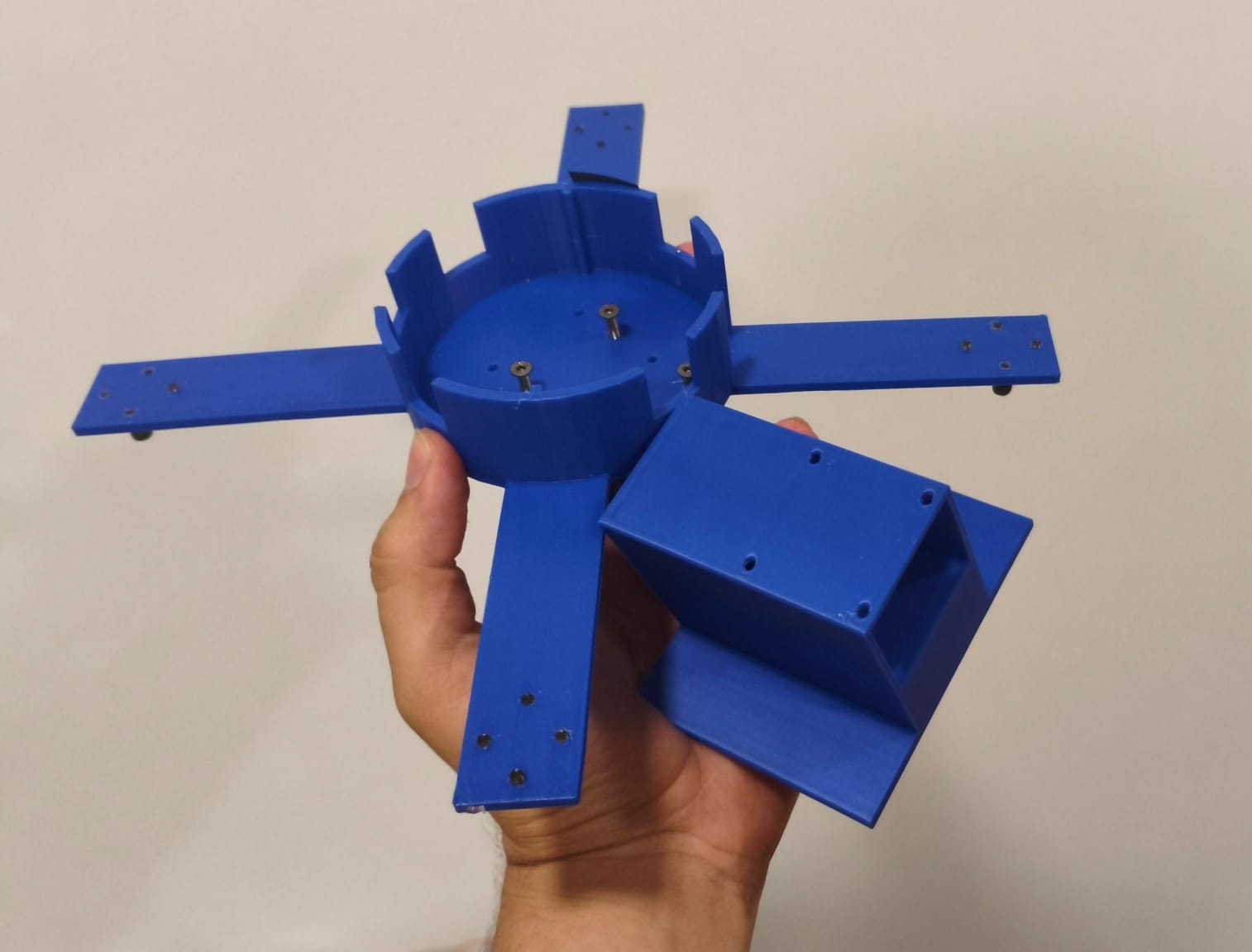
The Definitive Prototype
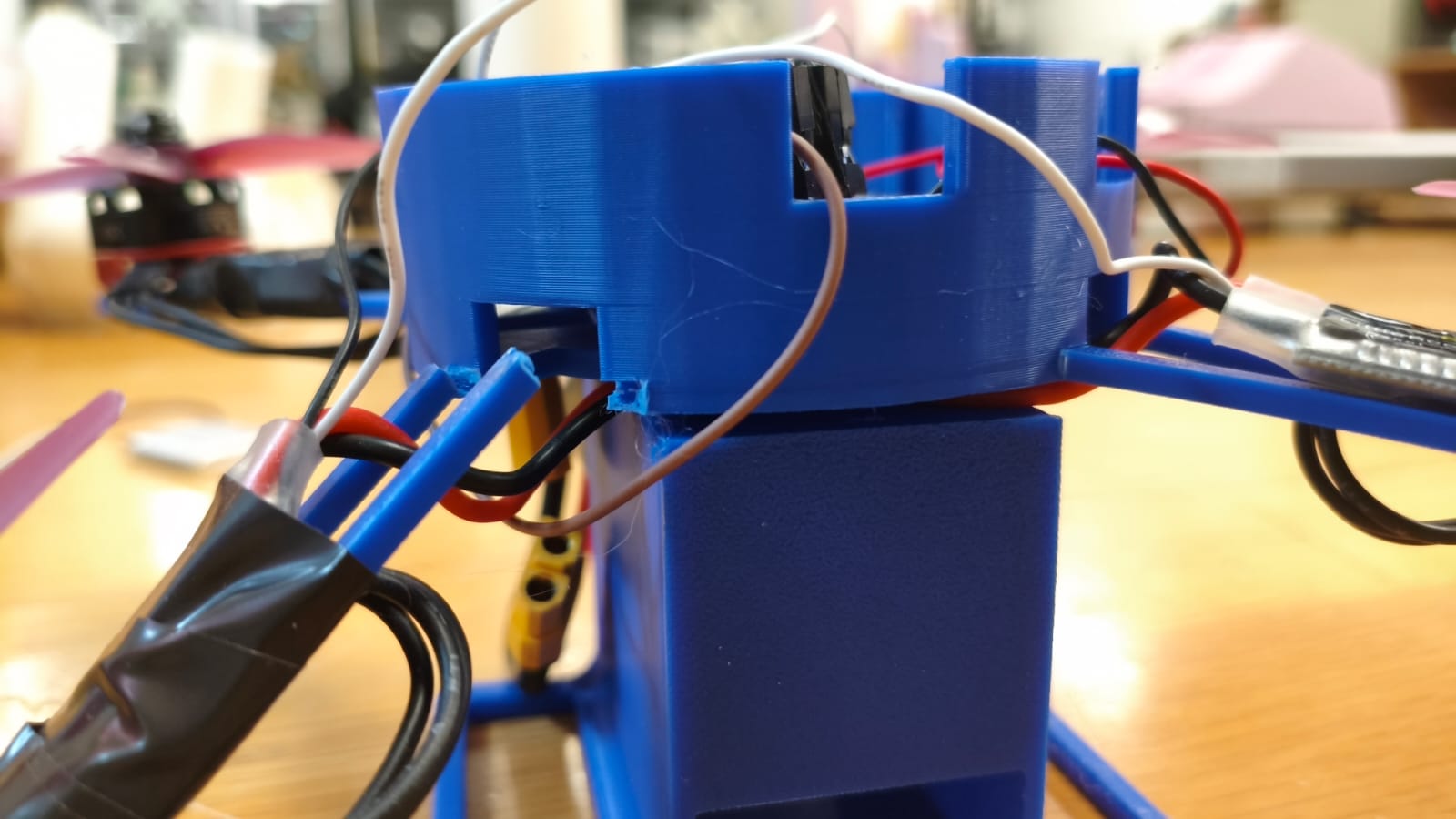
After the accident, I realized a lot of things. First of all, I needed to make stronger joints and structure for damage and impacts with the ground. Then, I had to modify all the wiring location for a more balanced and comfortable storage inside the drone, so I came up with this design:
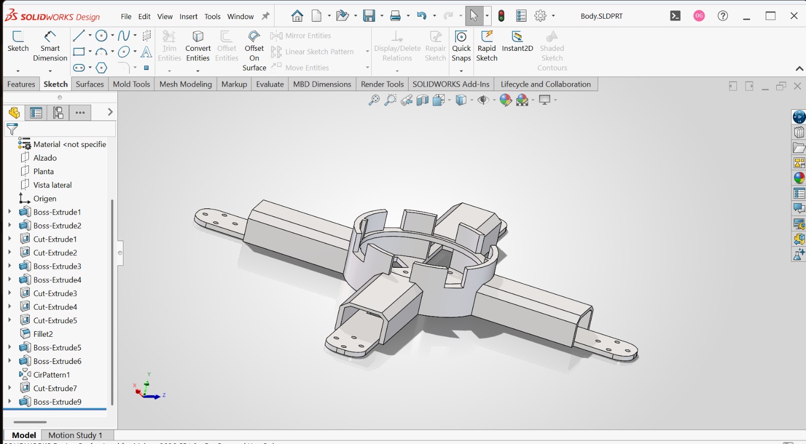
3D design with better ESC distribution and improved balance.
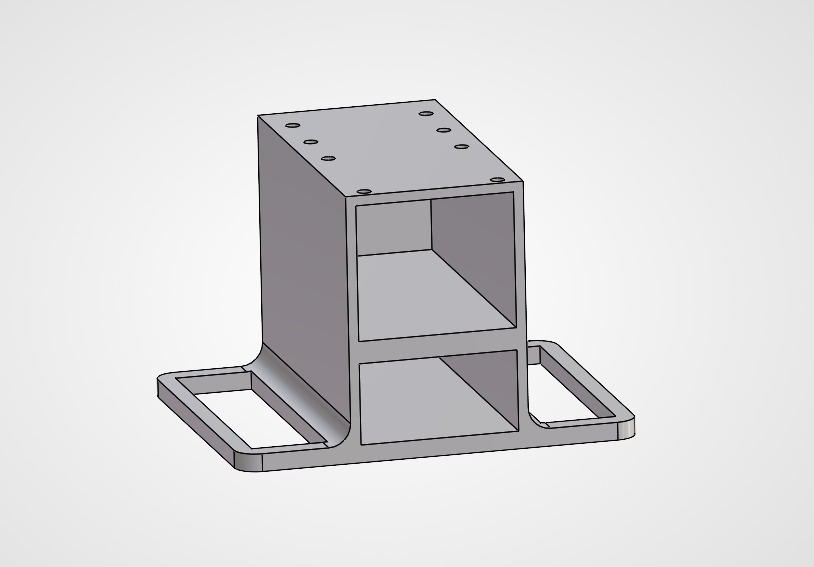
3D design of the battery holder with holes for screws and a base for the Drone.
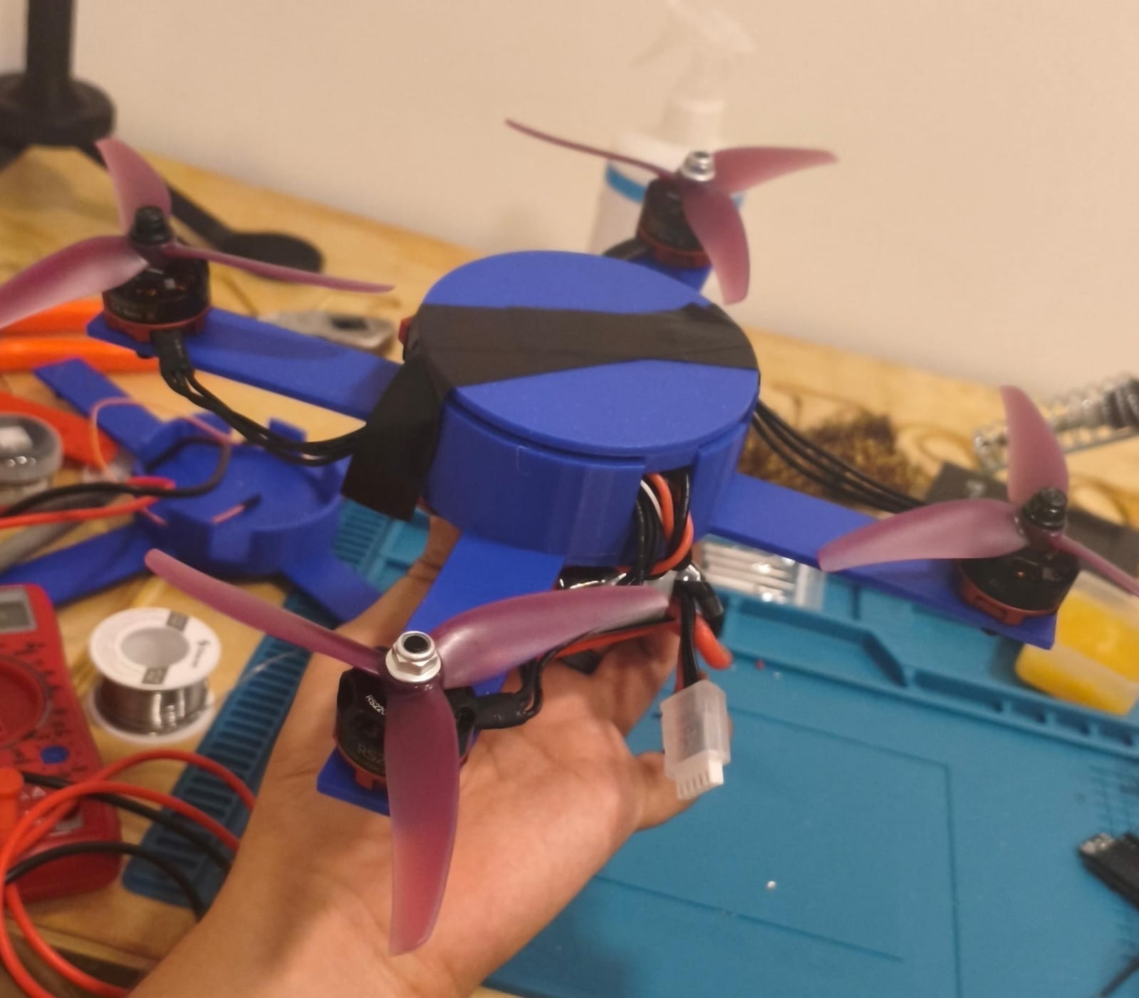
After printing the improved body of the Drone, I removed the support material and checked if everything fit properly for the final assembly.
Final body of the drone.
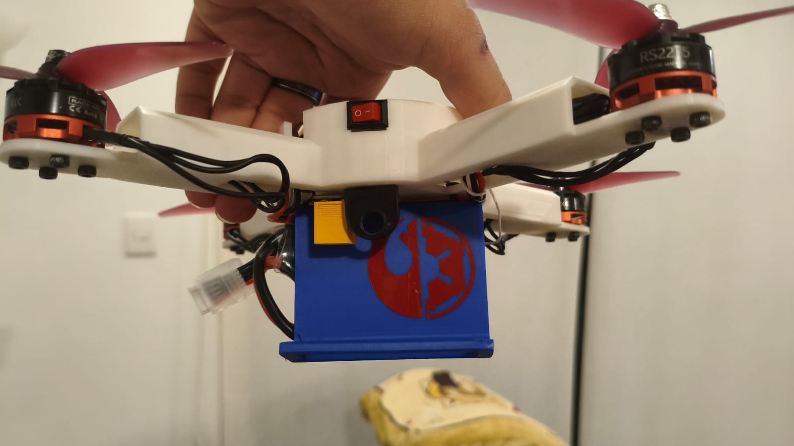
Final Drone Assembly
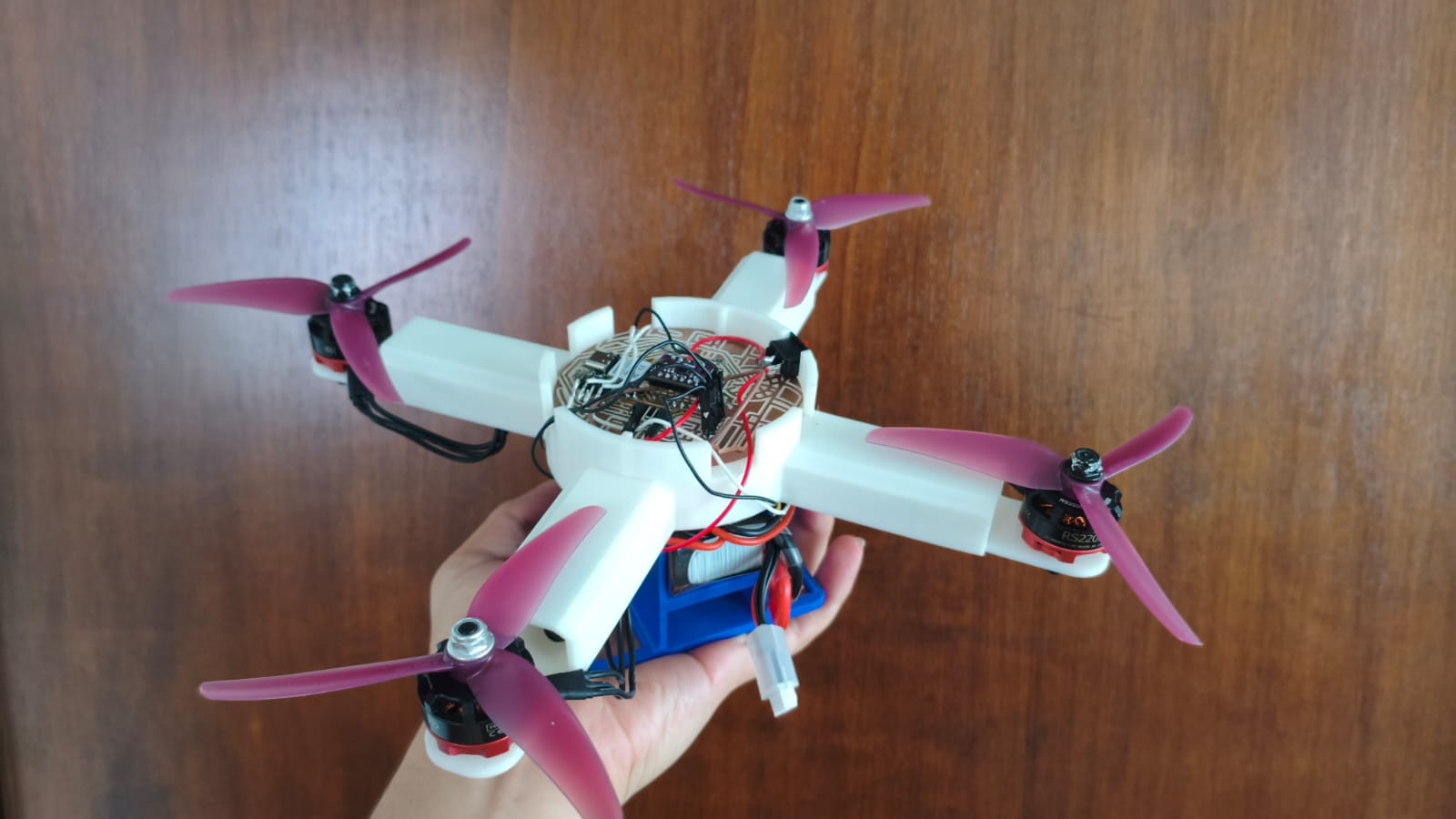
Final assembly of the drone.
RC Controller Designing
In this section, I'll be mentioning everything about the making process of the RC controller (besides the PCB making).
First, I took measurements of the PCB, the joystick, and the power switch, and then I designed the controller case in SOLIDWORKS.
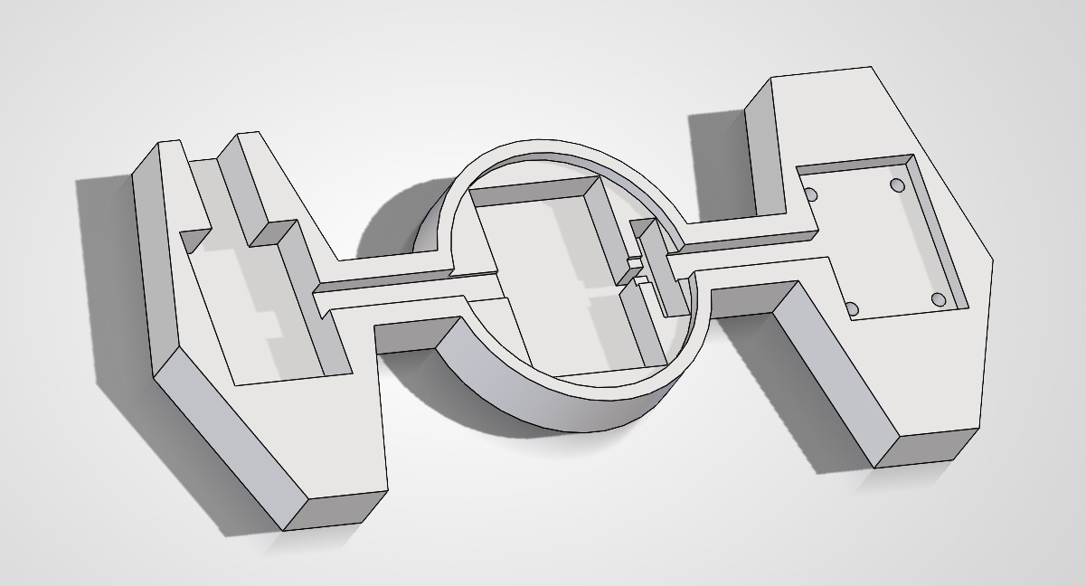
3D designed case for the controller.
After designing the part, I 3D printed it and then I placed the components that I would use on it, which are the Joystick with all its pinout, the XIAO ESP32-C6, the 3.7V rechargeable LiPo Battery, the power switch, some LEDs, and some resistors. Here in this video, I applied the knowledge that I obtained in the System Integration Week for making comfortable space to put the wires and components.
Now let's go to the most interesting and difficult part.
Making the PID controller
A Proportional, Integral, and Derivative (PID) controller is a fundamental feedback control loop mechanism in embedded systems engineering. It continuously calculates an error value as the difference between a desired setpoint and a measured process variable. For the creation of H.E.R.M.E.S., the PID is extremely important: it is literally the brain that keeps the drone's center of gravity stable in the air, compensating for external forces and successfully stabilizing both the pitch and roll axes so it doesn't crash instantly.
To tackle this massive challenge, I divided the programming and tuning process into two distinct phases: one using an isolated balancer rig, and a slightly more homemade setup, but testing with the complete drone.
Phase 1: The Balancer
First, I designed and 3D-printed a testing balancer. This allowed me to isolate a single axis of movement to deeply understand the mathematical concept of the PID loop and how to apply the correct PWM pulses to the brushless motors.
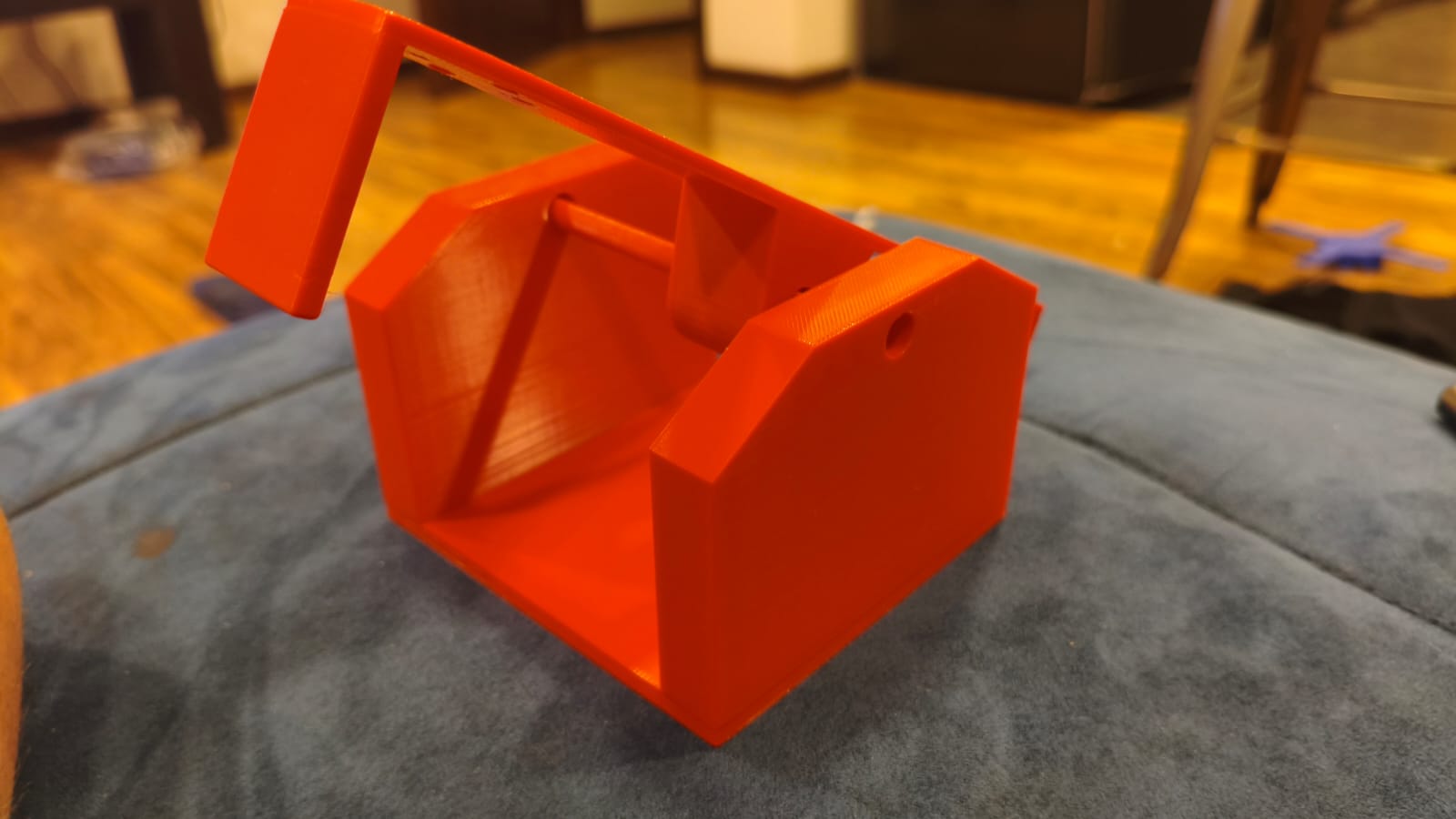
3D printed parts for the testing balancer.
Fully assembled balancer ready for initial tuning.
If you want to dive into the technical details of how I learned and applied this calibration phase, you can visit my Week 16: Wildcard Week →
Phase 2: The Homemade Test Rig
Once I understood the theory, I moved on to a more homemade version with the fully assembled drone. Using two sticks and two heavy objects to hold the ends, I built a test rig to calculate and tune the variables (Kp, Ki, Kd) while the actual drone was attached. This gave me a much more precise range of how the system would behave with its total take-off weight.
PID Code Snippet
Below is the logic implemented for the PID control:
#include <stdio.h>
#include <string.h>
#include <math.h>
#include "freertos/FreeRTOS.h"
#include "freertos/task.h"
#include "driver/i2c.h"
#include "driver/ledc.h"
#include "esp_timer.h"
#include "esp_err.h"
#include "esp_wifi.h"
#include "esp_now.h"
#include "nvs_flash.h"

#define I2C_MASTER_SCL_IO           23
#define I2C_MASTER_SDA_IO           22
#define I2C_MASTER_NUM              0
#define I2C_MASTER_FREQ_HZ          100000
#define SENSOR_ADDR                 0x68

#define ESC_FL_GPIO                 21
#define ESC_FR_GPIO                 1
#define ESC_RL_GPIO                 0
#define ESC_RR_GPIO                 2

#define LEDC_MODE                   LEDC_LOW_SPEED_MODE
#define LEDC_TIMER                  LEDC_TIMER_0
#define LEDC_DUTY_RES               LEDC_TIMER_14_BIT
#define LEDC_FREQUENCY              50

#define MIN_DUTY                    819
#define MAX_DUTY                    1638

#define MIN_FLIGHT_THROTTLE         0.01f
#define MAX_FLIGHT_THROTTLE         0.75f
#define RAMP_DURATION_SEC           2.0f

float HOVER_POWER_FL = 0.37f;
float HOVER_POWER_FR = 0.45f;
float HOVER_POWER_RL = 0.32f;
float HOVER_POWER_RR = 0.33f;

#define RAD_TO_DEG                  57.29577951f
#define ALPHA                       0.98f
#define GYRO_SCALE                  16.4f

float Kp_pitch = 0.00036f;
float Ki_pitch = 0.0000003f;
float Kd_pitch = 0.00018f; // Punto de partida para el amortiguamiento

// Mismos valores para Roll por simetría, aunque estés probando Pitch
float Kp_roll = 0.00250f;
float Ki_roll = 0.0000003f;
float Kd_roll = 0.000008f;

float prev_error_pitch = 0.0f, integral_pitch = 0.0f;
float prev_error_roll = 0.0f,  integral_roll = 0.0f;

float prev_derivative_pitch = 0.0f;
float prev_derivative_roll = 0.0f;
float LPF_BETA = 0.4f;

typedef struct struct_message {
    float joystick_x;
    float joystick_y;
    bool kill_switch_btn;
} struct_message;

struct_message incoming_data;
volatile bool remote_button_pressed = false;
volatile bool flight_active = false;

void on_data_recv(const esp_now_recv_info_t * esp_now_info, const uint8_t *data, int data_len) {
    if (data_len == sizeof(incoming_data)) {
        memcpy(&incoming_data, data, sizeof(incoming_data));
        remote_button_pressed = incoming_data.kill_switch_btn;
    }
}

static esp_err_t i2c_master_init(void) {
    i2c_config_t conf = {
        .mode = I2C_MODE_MASTER,
        .sda_io_num = I2C_MASTER_SDA_IO,
        .scl_io_num = I2C_MASTER_SCL_IO,
        .sda_pullup_en = GPIO_PULLUP_ENABLE,
        .scl_pullup_en = GPIO_PULLUP_ENABLE,
        .master.clk_speed = I2C_MASTER_FREQ_HZ,
    };
    i2c_param_config(I2C_MASTER_NUM, &conf);
    return i2c_driver_install(I2C_MASTER_NUM, conf.mode, 0, 0, 0);
}

void set_motor_speed(ledc_channel_t channel, float throttle) {
    uint32_t duty = MIN_DUTY + (uint32_t)(throttle * (MAX_DUTY - MIN_DUTY));
    ledc_set_duty(LEDC_MODE, channel, duty);
    ledc_update_duty(LEDC_MODE, channel);
}

float clamp_throttle(float value) {
    if (value < MIN_FLIGHT_THROTTLE) return MIN_FLIGHT_THROTTLE;
    if (value > MAX_FLIGHT_THROTTLE) return MAX_FLIGHT_THROTTLE;
    return value;
}

void app_main(void) {
    esp_err_t ret = nvs_flash_init();
    if (ret == ESP_ERR_NVS_NO_FREE_PAGES || ret == ESP_ERR_NVS_NEW_VERSION_FOUND) {
        ESP_ERROR_CHECK(nvs_flash_erase());
        nvs_flash_init();
    }
    wifi_init_config_t cfg = WIFI_INIT_CONFIG_DEFAULT();
    esp_wifi_init(&cfg);
    esp_wifi_set_mode(WIFI_MODE_STA);
    esp_wifi_start();
    esp_now_init();
    esp_now_register_recv_cb((esp_now_recv_cb_t)on_data_recv);
    i2c_master_init();

    ledc_timer_config_t ledc_timer = {
        .speed_mode = LEDC_MODE, .timer_num = LEDC_TIMER,
        .duty_resolution = LEDC_DUTY_RES, .freq_hz = LEDC_FREQUENCY, .clk_cfg = LEDC_AUTO_CLK
    };
    ledc_timer_config(&ledc_timer);

    int esc_pins[4] = {ESC_FL_GPIO, ESC_FR_GPIO, ESC_RL_GPIO, ESC_RR_GPIO};
    ledc_channel_t esc_channels[4] = {LEDC_CHANNEL_0, LEDC_CHANNEL_1, LEDC_CHANNEL_2, LEDC_CHANNEL_3};

    for (int i = 0; i < 4; i++) {
        ledc_channel_config_t ledc_channel = {
            .speed_mode = LEDC_MODE, .channel = esc_channels[i], .timer_sel = LEDC_TIMER,
            .intr_type = LEDC_INTR_DISABLE, .gpio_num = esc_pins[i], .duty = MIN_DUTY, .hpoint = 0
        };
        ledc_channel_config(&ledc_channel);
    }

    for (int i = 0; i < 4; i++) set_motor_speed(esc_channels[i], 0.0f);

    printf("[1/4] H.E.R.M.E.S. online. Waiting 2 seconds.\n");
    vTaskDelay(pdMS_TO_TICKS(2000));

    uint8_t cmd_reg = 0x7E;
    uint8_t write_accel[2] = {cmd_reg, 0x11};
    uint8_t write_gyro[2]  = {cmd_reg, 0x15};
    i2c_master_write_to_device(I2C_MASTER_NUM, SENSOR_ADDR, write_accel, 2, 1000 / portTICK_PERIOD_MS);
    vTaskDelay(50 / portTICK_PERIOD_MS);
    i2c_master_write_to_device(I2C_MASTER_NUM, SENSOR_ADDR, write_gyro, 2, 1000 / portTICK_PERIOD_MS);
    vTaskDelay(100 / portTICK_PERIOD_MS);

    printf("[2/4] Preparing IMU offset calibration. KEEP H.E.R.M.E.S. STILL.\n");
    printf("Starting scan in 2 seconds...\n");
    vTaskDelay(pdMS_TO_TICKS(2000));

    printf("Scanning for 7 seconds (700 samples)... Do not touch.\n");
    float offset_x = 0.0f, offset_y = 0.0f;
    int samples = 700;
    uint8_t reg = 0x0C, memoria[12];

    for (int i = 0; i < samples; i++) {
        if (i2c_master_write_read_device(I2C_MASTER_NUM, SENSOR_ADDR, ®, 1, memoria, 12, 100 / portTICK_PERIOD_MS) == ESP_OK) {
            int16_t accel_x_raw = (memoria[7] << 8) | memoria[6];
            int16_t accel_y_raw = (memoria[9] << 8) | memoria[8];
            int16_t accel_z_raw = (memoria[11] << 8) | memoria[10];
            offset_x += atan2f(accel_x_raw, accel_z_raw) * RAD_TO_DEG;
            offset_y += atan2f(accel_y_raw, accel_z_raw) * RAD_TO_DEG;
        }
        vTaskDelay(10 / portTICK_PERIOD_MS);
    }
    offset_x /= samples; offset_y /= samples;
    printf("Calibration complete. Offsets stored.\n");

    printf("[3/4] Sending armed idle pulse to ESCs... Waiting 3 seconds.\n");
    vTaskDelay(pdMS_TO_TICKS(3000));
    printf("[4/4] H.E.R.M.E.S. PID CONTROL ACTIVE.\n");

    float angle_x = 0.0f, angle_y = 0.0f;
    uint64_t last_time = esp_timer_get_time();

    uint64_t last_print_time = esp_timer_get_time();
    const uint64_t PRINT_INTERVAL_US = 250000;

    bool last_btn_state = false;
    float ramp_progress = 0.0f;

    while (1) {
        bool current_btn_state = remote_button_pressed;
        if (current_btn_state && !last_btn_state) {
            flight_active = !flight_active;
            if (flight_active) {
                ramp_progress = 0.0f;
                integral_pitch = 0.0f;
                integral_roll = 0.0f;
                prev_derivative_pitch = 0.0f;
                prev_derivative_roll = 0.0f;
            } else {
                printf("\n>>> STOP <<<\n\n");
            }
        }
        last_btn_state = current_btn_state;

        if (i2c_master_write_read_device(I2C_MASTER_NUM, SENSOR_ADDR, ®, 1, memoria, 12, 100 / portTICK_PERIOD_MS) == ESP_OK) {

            uint64_t current_time = esp_timer_get_time();
            float dt = (current_time - last_time) / 1000000.0f;
            if (dt <= 0.0f) dt = 0.001f;
            last_time = current_time;

            int16_t gyro_x_raw = (memoria[1] << 8) | memoria[0];
            int16_t gyro_y_raw = (memoria[3] << 8) | memoria[2];
            int16_t accel_x_raw = (memoria[7] << 8) | memoria[6];
            int16_t accel_y_raw = (memoria[9] << 8) | memoria[8];
            int16_t accel_z_raw = (memoria[11] << 8) | memoria[10];

            float accel_angle_x = atan2f(accel_x_raw, accel_z_raw) * RAD_TO_DEG;
            float accel_angle_y = atan2f(accel_y_raw, accel_z_raw) * RAD_TO_DEG;
            float gyro_rate_x = gyro_x_raw / GYRO_SCALE;
            float gyro_rate_y = gyro_y_raw / GYRO_SCALE;

            angle_x = ALPHA * (angle_x + gyro_rate_x * dt) + (1.0f - ALPHA) * accel_angle_x;
            angle_y = ALPHA * (angle_y + gyro_rate_y * dt) + (1.0f - ALPHA) * accel_angle_y;

            float calibrated_pitch = angle_x - offset_x;
            float calibrated_roll = angle_y - offset_y;

            if (current_time - last_print_time >= PRINT_INTERVAL_US) {
                printf("Pitch: %6.2f° | Roll: %6.2f°\n", calibrated_pitch, calibrated_roll);
                last_print_time = current_time;
            }

            if (flight_active) {
                if (ramp_progress < 1.0f) {
                    ramp_progress += (dt / RAMP_DURATION_SEC);
                    if (ramp_progress > 1.0f) ramp_progress = 1.0f;
                }

                float base_FL = MIN_FLIGHT_THROTTLE + ((HOVER_POWER_FL - MIN_FLIGHT_THROTTLE) * ramp_progress);
                float base_FR = MIN_FLIGHT_THROTTLE + ((HOVER_POWER_FR - MIN_FLIGHT_THROTTLE) * ramp_progress);
                float base_RL = MIN_FLIGHT_THROTTLE + ((HOVER_POWER_RL - MIN_FLIGHT_THROTTLE) * ramp_progress);
                float base_RR = MIN_FLIGHT_THROTTLE + ((HOVER_POWER_RR - MIN_FLIGHT_THROTTLE) * ramp_progress);

                float error_pitch = 0.0f - calibrated_pitch;
                float error_roll = 0.0f - calibrated_roll;

                integral_pitch += error_pitch * dt;
                if(integral_pitch > 50.0f) integral_pitch = 50.0f; else if(integral_pitch < -50.0f) integral_pitch = -50.0f;

                integral_roll += error_roll * dt;
                if(integral_roll > 50.0f) integral_roll = 50.0f; else if(integral_roll < -50.0f) integral_roll = -50.0f;

                float raw_derivative_pitch = (error_pitch - prev_error_pitch) / dt;
                float raw_derivative_roll = (error_roll - prev_error_roll) / dt;

                float derivative_pitch = (LPF_BETA * raw_derivative_pitch) + ((1.0f - LPF_BETA) * prev_derivative_pitch);
                float derivative_roll = (LPF_BETA * raw_derivative_roll) + ((1.0f - LPF_BETA) * prev_derivative_roll);

                prev_derivative_pitch = derivative_pitch;
                prev_derivative_roll = derivative_roll;
                prev_error_pitch = error_pitch;
                prev_error_roll = error_roll;

                float pid_pitch_output = (Kp_pitch * error_pitch) + (Ki_pitch * integral_pitch) + (Kd_pitch * derivative_pitch);
                float pid_roll_output = (Kp_roll * error_roll) + (Ki_roll * integral_roll) + (Kd_roll * derivative_roll);

                float target_FL = base_FL - pid_pitch_output - pid_roll_output;
                float target_FR = base_FR - pid_pitch_output + pid_roll_output;
                float target_RL = base_RL + pid_pitch_output - pid_roll_output;
                float target_RR = base_RR + pid_pitch_output + pid_roll_output;

                target_FL = clamp_throttle(target_FL);
                target_FR = clamp_throttle(target_FR);
                target_RL = clamp_throttle(target_RL);
                target_RR = clamp_throttle(target_RR);

                set_motor_speed(esc_channels[0], target_FL);
                set_motor_speed(esc_channels[1], target_FR);
                set_motor_speed(esc_channels[2], target_RL);
                set_motor_speed(esc_channels[3], target_RR);

            } else {
                for (int i = 0; i < 4; i++) set_motor_speed(esc_channels[i], 0.0f);
            }
        }
        vTaskDelay(10 / portTICK_PERIOD_MS);
    }
}
Networking and Communications (ESP-NOW)
To establish a wireless link between the controller and the drone, I used the ESP-NOW protocol. This is a connectionless communication technology developed by Espressif that allows microcontrollers to communicate directly with each other without needing a Wi-Fi router. It is incredibly fast, operates with very low latency, and has a range of approximately 200 meters in open spaces, making it ideal for RC vehicles.
In this setup, the remote control acts as the sender and H.E.R.M.E.S. as the receiver. Pressing the joystick button sends a signal to start (or arm) the drone's motors. Once active, the potentiometer values from the joystick are constantly transmitted to program and control the forward movement and rotation of the drone.
Setup of the remote controller ready for transmission.
Code for the ESP-NOW Controller
Here is the code for the ESP-NOW Tie Fighter Rc Controller, sends constantly its values for turning On and Off the propellers of the Drone:
#include <stdio.h>
#include <stdbool.h>
#include <string.h>
#include "freertos/FreeRTOS.h"
#include "freertos/task.h"
#include "driver/gpio.h"
#include "esp_wifi.h"
#include "esp_now.h"
#include "nvs_flash.h"

#define BUTTON_PIN GPIO_NUM_20
#define LED_PIN    GPIO_NUM_15

uint8_t hermes_mac[] = {0x98, 0xA3, 0x16, 0x8D, 0xF3, 0x28};

typedef struct struct_message {
    float joystick_x;
    float joystick_y;
    bool kill_switch_btn;
} struct_message;

struct_message control_data;

void on_data_sent(const uint8_t *mac_addr, esp_now_send_status_t status) {
    if (status == ESP_NOW_SEND_SUCCESS) {
    } else {
        printf("Delivery failed. Is the drone powered off?\n");
    }
}

void app_main(void) {
    gpio_config_t btn_conf = {
        .pin_bit_mask = (1ULL << BUTTON_PIN),
        .mode = GPIO_MODE_INPUT,
        .pull_up_en = 1,
        .pull_down_en = 0,
        .intr_type = GPIO_INTR_DISABLE
    };
    gpio_config(&btn_conf);

    gpio_config_t led_conf = {
        .pin_bit_mask = (1ULL << LED_PIN),
        .mode = GPIO_MODE_OUTPUT,
        .pull_up_en = 0,
        .pull_down_en = 0,
        .intr_type = GPIO_INTR_DISABLE
    };
    gpio_config(&led_conf);

    gpio_set_level(LED_PIN, 1);

    esp_err_t ret = nvs_flash_init();
    if (ret == ESP_ERR_NVS_NO_FREE_PAGES || ret == ESP_ERR_NVS_NEW_VERSION_FOUND) {
        ESP_ERROR_CHECK(nvs_flash_erase());
        ret = nvs_flash_init();
    }
    ESP_ERROR_CHECK(ret);

    wifi_init_config_t cfg = WIFI_INIT_CONFIG_DEFAULT();
    ESP_ERROR_CHECK(esp_wifi_init(&cfg));
    ESP_ERROR_CHECK(esp_wifi_set_mode(WIFI_MODE_STA));
    ESP_ERROR_CHECK(esp_wifi_start());

    ESP_ERROR_CHECK(esp_wifi_set_max_tx_power(80));

    if (esp_now_init() != ESP_OK) {
        printf("Fatal Error: Could not initialize ESP-NOW\n");
        return;
    }
    ESP_ERROR_CHECK(esp_now_register_send_cb((esp_now_send_cb_t)on_data_sent));

    esp_now_peer_info_t peerInfo = {};
    memcpy(peerInfo.peer_addr, hermes_mac, 6);
    peerInfo.channel = 0;
    peerInfo.encrypt = false;

    if (esp_now_add_peer(&peerInfo) != ESP_OK) {
        printf("Error: Could not add H.E.R.M.E.S. to the network\n");
        return;
    }

    printf("======================================\n");
    printf("XIAO REMOTE CONTROL INITIATED\n");
    printf("Searching for drone with MAC: 98:A3:16:8D:F3:28\n");
    printf("======================================\n");

    while (1) {
        int button_state = gpio_get_level(BUTTON_PIN);

        control_data.kill_switch_btn = (button_state == 0) ? true : false;

        gpio_set_level(LED_PIN, (button_state == 0) ? 0 : 1);

        control_data.joystick_x = 0.0f;
        control_data.joystick_y = 0.0f;

        esp_now_send(hermes_mac, (uint8_t *) &control_data, sizeof(control_data));

        if(control_data.kill_switch_btn) {
            printf("KILL SWITCH PRESSED! Sending emergency signal...\n");
            vTaskDelay(pdMS_TO_TICKS(100));
        } else {
            vTaskDelay(pdMS_TO_TICKS(20));
        }
    }
}
And here we have a test showing the reliability of the controller and its fast connection with the drone:
Flight Tests
Once the baseline PID was calculated, it was time to fly! However, getting a vehicle built from scratch to take off and hover stably is an incredibly complicated process for a homemade project in such a short amount of time. It requires surgical precision in the code tuning to get a satisfactory result.
First take-off attempt (Fail).
Second flight attempt (Fail).
After several attempts, broken props, and adjusting variables, I managed to make the drone take off. Unfortunately, because the system still requires a much better and finer tuning, it lost stability and fell down rather quickly.
"Even though the Fab Academy program is coming to an end, the development of H.E.R.M.E.S. continues. I will take several weeks to keep refining the software, but I am committed to making a perfectly balanced drone ready for racing."
Vinyl Cutting (Subtractive Manufacturing)
To fulfill the requirement of including a subtractive manufacturing method, I decided to add some personalization to the drone. Thanks to the skills I learned during Week 3: Computer Controlled Cutting →, I designed and cut a Star Wars figure out of vinyl to decorate the chassis, perfectly matching the theme of the electronics.

Star Wars vinyl figure design.
The final vinyl cut applied to the project.
Hero Shots
Here is the final visual result of my Fab Academy project, showcasing both H.E.R.M.E.S. and its custom RC controller.
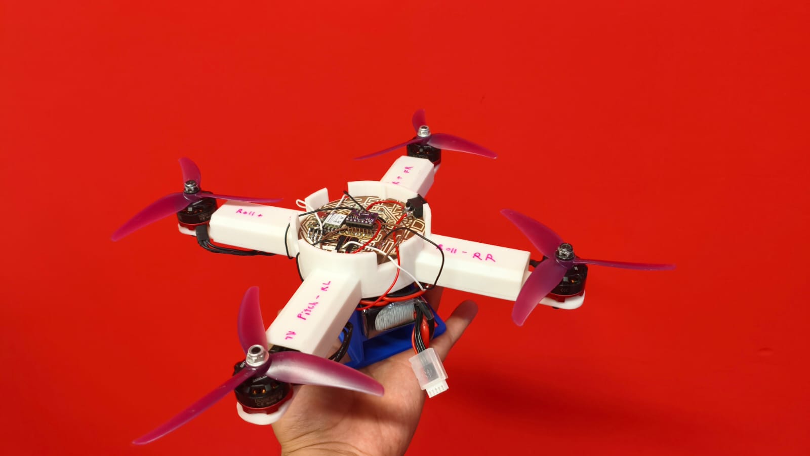
H.E.R.M.E.S. fully assembled.
The custom ESP32-C6 remote controller.
And here is the final take-off video:
*Note: I am still working on tuning the PID controller for perfect flight. If the repository can be edited in the future, I will update this section with a video of the drone flying perfectly!
Original Files (Downloads)
Here you can find all the original files created during the development of H.E.R.M.E.S. Feel free to download, study, and replicate the project for your own builds.
| Category | Description | Download Link |
|---|---|---|
| 3D Design (CAD) | Chassis, battery holder, top cover, and RC controller case files (STL / SLDPRT). | Download 3D Files ↓ |
| Electronics (PCB) | Schematics, board layouts, and Gerber files for the Master Drone board and the RC Controller. | Download PCB Files ↓ |
| Software (Code) | ESP-IDF C code for the flight controller, PID tuning loop, and ESP-NOW remote link. | Download Source Code ↓ |