

Week 16
Wildcard Week: AI Vision & Physical Computing
// MAIN OBJECTIVE \\
Design and produce something using a digital process—incorporating computer-aided design and manufacturing—not covered elsewhere, documenting the requirements my assignment satisfies.
What is Artificial Intelligence (AI)?
Artificial Intelligence is a branch of computer science that aims to create systems capable of performing tasks that traditionally require human intelligence. This includes learning, reasoning, problem-solving, pattern recognition, and language understanding. Unlike traditional programming, where we dictate strict rules through code like if/else statements, AI learns these rules by analyzing massive amounts of data through neural networks.
How is an AI Trained?
Training an Artificial Intelligence is like teaching a child to recognize a dog. You don't give them a mathematical formula; you show them thousands of pictures of dogs. In Machine Learning, a neural network is fed massive amounts of data like millions of images of human hands in different positions, lighting, and angles. Through trial and error, the network adjusts its internal math until it can successfully identify hand patterns on its own.
How did I train this AI?
The truth is, I didn't have to train it from scratch! Training a robust vision model requires massive server farms, time, and datasets. Instead, I used a concept called pre-trained models. I am utilizing an AI that was already trained by Google researchers with millions of hand images. My job for this assignment was to import this brain into my webpage and write the logic to connect its data to my physical hardware.Types of Artificial Intelligence
Although the term AI is very broad, it is currently divided into several main categories based on its application:
- Natural Language Processing: Models trained to understand and generate text, like ChatGPT or Gemini. They can translate, summarize, or even write code.
- Generative AI: Systems capable of creating completely new content, such as images or audio, from textual descriptions.
- Reinforcement Learning: AIs that learn through trial and error within an environment, rewarding correct actions. This is widely used in robotics.
- Computer Vision: Systems designed to "see" and understand the digital or physical world through cameras, recognizing objects, faces, postures, or gestures (This is the category my project focuses on).
The Chosen One: ml5.js & MediaPipe
For this project, I decided to use a Computer Vision model through a library called ml5.js. But what exactly is driving this?
It uses MediaPipe. which is an open-source framework created by Google. It is designed to process video streams in real-time and execute highly complex machine learning tasks like tracking faces, body poses, or hands incredibly fast, even on standard laptops or mobile phones.
To use MediaPipe easily, I used ml5.js, which is a friendly wrapper library designed to make machine learning accessible to artists, makers, and students. The link you see in my HTML code (<script src="https://unpkg.com/ml5@0.12.2/dist/ml5.min.js"></script>) was taken directly from the official ml5.js documentation. By just pasting this link into my code, the browser downloads the entire pre-trained hand-tracking brain instantly from the internet without having to install any complex software.
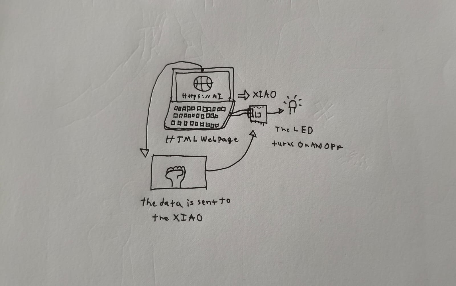
Why does it need a webpage and a microcontroller at the same time?
The AI model requires significant processing power and direct access to video frames from a camera. Running a heavy neural network directly on a microcontroller like the ESP32-C6 is highly inefficient and complex.
The most efficient solution is to divide the workload: The webpage (the browser) acts as the brain, it uses the computer's CPU/GPU to process the real-time video and deduce the hand's position. However, a webpage lives in a virtual sandbox and cannot turn on physical lights or move motors in the real world.
This is where the microcontroller (XIAO ESP32-C6) comes in, acting as the "muscle". Through the Web Serial API, the browser sends basic text commands via USB to the ESP32. The C code (ESP-IDF) reads these commands and actuates the physical pins. This combination gives us complex image processing and physical hardware actuation.
How does the hand detection work?
The neural model analyzes the video stream and overlays a vector mesh of 21 points onto the detected hand. Each point has precise X and Y coordinates on the screen.

To differentiate between an Open Hand and a Closed Fist, I applied simple geometric logic using JavaScript:
- The Y-coordinates of the fingertips are compared with the Y-coordinates of the finger bases.
- If the fingertips are located below the knuckles (higher Y value on the screen), it means the fingers are curled (Closed Fist).
- If the fingertips are above the knuckles, the hand is open.
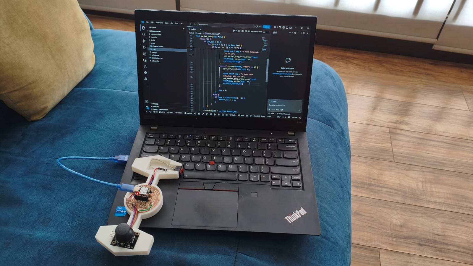
Hardware Setup
Below is my setup connected and ready to recieve the AI's commands:
How the System Works (A Step-by-Step Guide)
If you are not an engineer, bridging a virtual Artificial Intelligence with a physical LED might sound like magic. Here is the exact order of operations of what both codes (Web and C) do when you use the system:
- Plugging In: First, you connect the XIAO ESP32-C6 board to the computer using a standard USB cable.
- Webpage: You open the HTML webpage. The code immediately asks your browser for permission to turn on the laptop's webcam.
- Connecting the board: You click the "Connect to Board" button on the screen. The JavaScript code opens a secure "tunnel" (Web Serial API) between the webpage and the physical USB port where the board is plugged in.
- The AI in Action: As you put your hand in front of the camera, the ml5.js AI draws a digital skeleton with 21 points over your fingers. It constantly checks the math: Are the fingertips curled below the knuckles?
- Sending the Signal: If the AI detects your hand is closed, the webpage literally yells the text
CLOSED\nand sends it down the USB tunnel. If you open your hand, it sendsOPEN\n. - The Microcontroller Reacts: The C program running on the ESP32 does not know anything about cameras or AI; it just listens to the USB port. When it hears the word
CLOSED, it sends electrical current to Pin 17, turning the LED ON. When it hearsOPEN, it cuts the power, turning the LED OFF.
ESP-IDF C code
Here Is my code for this week. It isolates the reading of the USB JTAG port into an independent FreeRTOS task. This allows the microcontroller to interpret the strings sent by the web browser continuously without interrupting other background processes.
#include <stdio.h>
#include <string.h>
#include "freertos/FreeRTOS.h"
#include "freertos/task.h"
#include "driver/gpio.h"
#include "driver/usb_serial_jtag.h"

#define LED_PIN 17

void serial_task(void *arg) {
    char buffer[128];
    int pos = 0;
    uint8_t rx_buf[64];

    while (1) {
        //Read incoming data from the native USB port without blocking the system
        int rx_len = usb_serial_jtag_read_bytes(rx_buf, sizeof(rx_buf), 20 / portTICK_PERIOD_MS);

        if (rx_len > 0) {
            for (int i = 0; i < rx_len; i++) {
                char c = (char)rx_buf[i];

                //Build the string character by character until a newline is detected


                if (c == '\n' || c == '\r') {
                    if (pos > 0) {
                        buffer[pos] = '\0';

                        //Evaluate the command from the AI and actuate the hardware
                        if (strcmp(buffer, "CLOSED") == 0) {
                            gpio_set_level(LED_PIN, 1);

                            const char* msg = "> Fist detected. LED ON.\n";
                            usb_serial_jtag_write_bytes((const void*)msg, strlen(msg), 20 / portTICK_PERIOD_MS);
                        }
                        else if (strcmp(buffer, "OPEN") == 0) {
                            gpio_set_level(LED_PIN, 0);

                            const char* msg = "> Open hand detected. LED OFF.\n";
                            usb_serial_jtag_write_bytes((const void*)msg, strlen(msg), 20 / portTICK_PERIOD_MS);
                        }

                        pos = 0;
                    }
                } else {
                    if (pos < sizeof(buffer) - 1) {
                        buffer[pos++] = c;
                    }
                }
            }
        }

        vTaskDelay(10 / portTICK_PERIOD_MS);
    }
}

void app_main(void) {
    // Initialize the native USB JTAG driver to establish the Web Serial bridge
    usb_serial_jtag_driver_config_t usb_config = USB_SERIAL_JTAG_DRIVER_CONFIG_DEFAULT();
    usb_serial_jtag_driver_install(&usb_config);

    gpio_reset_pin(LED_PIN);
    gpio_set_direction(LED_PIN, GPIO_MODE_OUTPUT);
    gpio_set_level(LED_PIN, 0);


    xTaskCreate(serial_task, "serial_task", 4096, NULL, 5, NULL);
}
Final Results
Here are my final results of the week, If you want to go to the AI hand detection page click HERE →
// CONTINUOUS DEVELOPMENT \\
As an extra research component for this week, I continued the development of the autonomous stabilization algorithms for my drone project (H.E.R.M.E.S.). The following section documents the math and implementation of a PID controller.
PID Control System
What is a PID control system?
This is a complex algorithm which has a purpose: keep a variable on the setpoint by controlling something like a motor, coolant, valves, etc.. It works by using a closed-loop control mechanism, it evaluates the difference between a system's current state and the desired objective (setpoint), calculating corrective actions to automate and stabilize physical variables such as temperature, speed, pressure, or flow.
This system is divided in 3 parts: Proportional (P), Integral (I) and Derivative (D):
Proportional (P)
The proportional component reacts directly to the current error. It applies a correction that is proportional to the difference between the desired setpoint and the current value. The larger the error, the larger the correction. Its formula is: $$P_{out}=K_p\cdot e(t)$$
Derivative (D)
The derivative component predicts future behavior based on the rate of change of the error. It acts as a dampener, reducing the overshoot and the oscillations caused by the proportional term. Its formula is: $$D_{out}=K_d\cdot\frac{de(t)}{dt}$$
Integral (I)
The integral component accounts for the accumulation of past errors. If a small error persists over time (like a physical tilt that P and D cannot fix on their own), the integral term accumulates this error and applies a stronger correction to eliminate the steady-state error. Its formula is: $$I_{out}=K_i\cdot\int_{0}^{t}e(\tau)d\tau$$
Note: you can choose a P, PD, or PID control algorithm depending on how easy it is to control the setpoint variable.
Why is PID necessary for a Drone?
For my Final Project, I am aiming to build a fully autonomous drone. By the laws of physics, a multirotor drone is inherently unstable; without continuous control, it will simply flip and crash. It requires rapid, real-time micro-adjustments to the RPM of each motor to maintain a stable hover. The PID control system is exactly what calculates these adjustments. By taking orientation data from the BMI160 IMU sensor, the PID loop calculates the precise power needed for each motor to keep the drone perfectly level at a 0-degree setpoint.
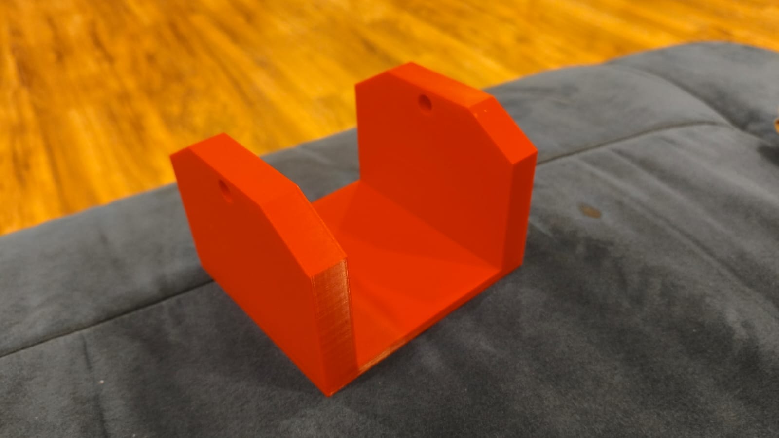
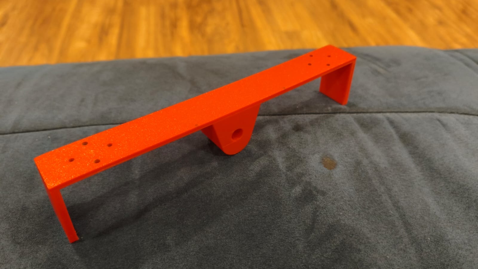
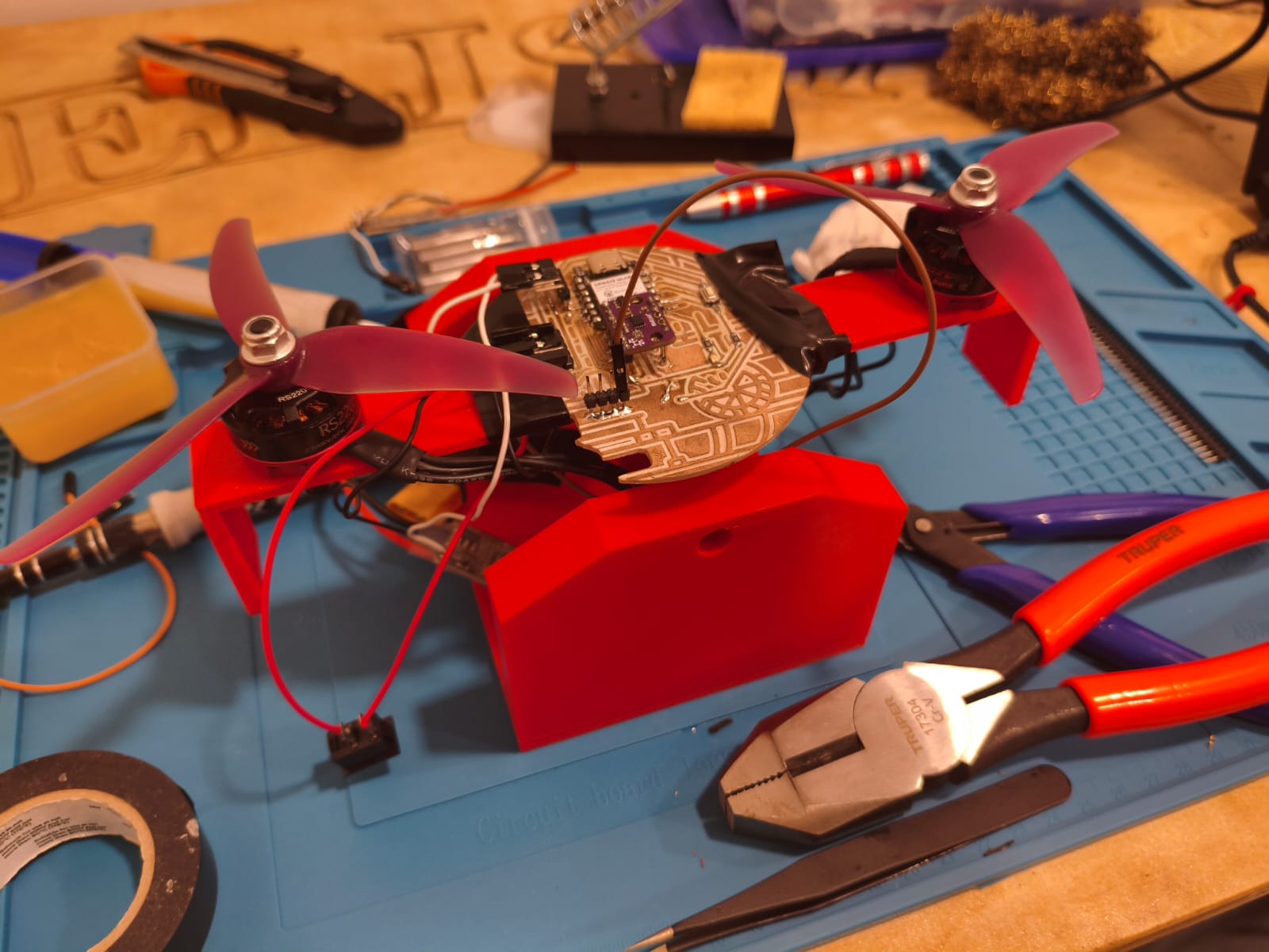
The 2-Propeller Balancer
To safely calibrate the PID system without risking the destruction of my drone during testing, I needed a controlled environment. My strategy was to build a 1-dimensional "balancer" with just 2 propellers. This setup takes the physical angle reference from the BMI160 sensor on a single axis. Based on this angle, the PID algorithm dynamically increases and decreases the thrust of the opposing brushless motors to balance the arm perfectly horizontally.
Design and Fabrication
I designed the entire balancer structure using SolidWorks. I needed a central pivot that offered low friction, solid motor mounts to withstand the thrust, and a rigid main arm to hold the electronics.
Once the CAD files were ready, I 3D printed all the components using PLA. After printing, the next step was mechanical assembly and electronics. I soldered the Electronic Speed Controllers (ESCs) that drive the motors and assembled the physical structure.

PID Tuning and Testing Process
Tuning a PID controller is an iterative process. I had to test and adjust each constant ($K_p$, $K_d$, and $K_i$) sequentially to achieve stable flight dynamics.
1. Proportional (P) Tuning
I started by isolating the Proportional term. As shown in the video below, when the angle difference is small, the system manages to stabilize. However, if I manually push the arm down to simulate a strong disturbance, the P-term's correction is too abrupt, and the balancer begins to oscillate constantly without stopping.
2. Derivative (D) Tuning
To stop the constant bouncing, I introduced the Derivative term. The D-term successfully anticipates the movement and damps the oscillation. However, it leaves us with a new issue: steady-state error. The oscillation stops, but the arm remains tilted rather than returning to a perfect 0-degree horizontal position.
3. Integral (I) Tuning
Finally, I added the Integral term to fix the tilt. For this final stage, I had to significantly increase the base power of the balancer because it needs to physically lift and make aggressive, real-time corrections at near-maximum thrust. Due to this high power, the system oscillates slightly more during the initial correction, but the Integral term perfectly pulls it to stabilize exactly at 0 degrees.
ESP-IDF C Code for PID Implementation
Here is the core logic I developed using pure C in the ESP-IDF framework. To understand how it works, imagine you are trying to balance a broom on your hand:
- The Eyes (Sensor): The code first reads the BMI160 sensor to check how much the balancer is leaning (the error).
- The Brain (PID Math): It then calculates how to fix this tilt using the Proportional, Integral, and Derivative math we saw above.
- The Muscles (Motors): Finally, it tells the left and right motors to spin faster or slower to bring the arm back to a perfect horizontal level.
It repeats this process 50 times every second to keep everything perfectly stable!
#include <stdio.h>
#include <math.h>
#include "freertos/FreeRTOS.h"
#include "freertos/task.h"
#include "driver/i2c.h"
#include "driver/ledc.h"
#include "esp_timer.h"
#include "esp_err.h"
// BMI160
#define I2C_MASTER_SCL_IO 23
#define I2C_MASTER_SDA_IO 22
#define I2C_MASTER_NUM 0
#define I2C_MASTER_FREQ_HZ 100000
#define SENSOR_ADDR 0x68
#define PI 3.14159265358979323846
//ESC
#define ESC_RIGHT_GPIO 0
#define ESC_LEFT_GPIO 1
#define LEDC_MODE LEDC_LOW_SPEED_MODE
#define LEDC_TIMER LEDC_TIMER_0
#define LEDC_DUTY_RES LEDC_TIMER_14_BIT
#define LEDC_FREQUENCY 50
#define MIN_DUTY 819
#define MAX_DUTY 1638
//Base Configuration
#define BASE_THROTTLE 0.18f
#define MIN_THROTTLE_LIMIT 0.18f
#define MAX_THROTTLE_LIMIT 0.99f
// TUNING
float Kp = 0.0015f;
float Ki = 0.005f;
float Kd = 0.00042f;
float integral_error = 0.0f;
float prev_error = 0.0f;
#define MAX_INTEGRAL_LIMIT 10.0f
static esp_err_t i2c_master_init(void) {
i2c_config_t conf = {
.mode = I2C_MODE_MASTER,
.sda_io_num = I2C_MASTER_SDA_IO,
.scl_io_num = I2C_MASTER_SCL_IO,
.sda_pullup_en = GPIO_PULLUP_ENABLE,
.scl_pullup_en = GPIO_PULLUP_ENABLE,
.master.clk_speed = I2C_MASTER_FREQ_HZ,
};
i2c_param_config(I2C_MASTER_NUM, &conf);
return i2c_driver_install(I2C_MASTER_NUM, conf.mode, 0, 0, 0);
}
void set_motor_speed(ledc_channel_t channel, float throttle) {
uint32_t duty = MIN_DUTY + (uint32_t)(throttle * (MAX_DUTY - MIN_DUTY));
ledc_set_duty(LEDC_MODE, channel, duty);
ledc_update_duty(LEDC_MODE, channel);
}
void app_main(void) {
ESP_ERROR_CHECK(i2c_master_init());
ledc_timer_config_t ledc_timer = {
.speed_mode = LEDC_MODE,
.timer_num = LEDC_TIMER,
.duty_resolution = LEDC_DUTY_RES,
.freq_hz = LEDC_FREQUENCY,
.clk_cfg = LEDC_AUTO_CLK
};
ledc_timer_config(&ledc_timer);
int esc_pins[2] = {ESC_RIGHT_GPIO, ESC_LEFT_GPIO};
ledc_channel_t esc_channels[2] = {LEDC_CHANNEL_0, LEDC_CHANNEL_1};
for (int i = 0; i < 2; i++) {
ledc_channel_config_t ledc_channel = {
.speed_mode = LEDC_MODE,
.channel = esc_channels[i],
.timer_sel = LEDC_TIMER,
.intr_type = LEDC_INTR_DISABLE,
.gpio_num = esc_pins[i],
.duty = MIN_DUTY,
.hpoint = 0
};
ledc_channel_config(&ledc_channel);
}
printf("Arming ESCs...\n");
set_motor_speed(esc_channels[0], 0.0f);
set_motor_speed(esc_channels[1], 0.0f);
vTaskDelay(pdMS_TO_TICKS(3000));
uint8_t cmd_reg = 0x7E;
uint8_t cmd_accel = 0x11, cmd_gyro = 0x15;
uint8_t write_accel[2] = {cmd_reg, cmd_accel};
uint8_t write_gyro[2] = {cmd_reg, cmd_gyro};
i2c_master_write_to_device(I2C_MASTER_NUM, SENSOR_ADDR, write_accel, 2, 1000 / portTICK_PERIOD_MS);
vTaskDelay(50 / portTICK_PERIOD_MS);
i2c_master_write_to_device(I2C_MASTER_NUM, SENSOR_ADDR, write_gyro, 2, 1000 / portTICK_PERIOD_MS);
vTaskDelay(100 / portTICK_PERIOD_MS);
uint8_t reg = 0x0C;
uint8_t memoria[12];
float filtered_pitch = 0.0f;
uint64_t tiempo_anterior = esp_timer_get_time();
while (1) {
if (i2c_master_write_read_device(I2C_MASTER_NUM, SENSOR_ADDR, ®, 1, memoria, 12, 100 / portTICK_PERIOD_MS) == ESP_OK) {
uint64_t tiempo_actual = esp_timer_get_time();
float dt = (tiempo_actual - tiempo_anterior) / 1000000.0f;
tiempo_anterior = tiempo_actual;
int16_t gyro_y_raw = (memoria[3] << 8) | memoria[2];
int16_t accel_x_raw = (memoria[7] << 8) | memoria[6];
int16_t accel_y_raw = (memoria[9] << 8) | memoria[8];
int16_t accel_z_raw = (memoria[11] << 8) | memoria[10];
float gyro_y_rate = gyro_y_raw / 16.4f;
float g_x = accel_x_raw / 16384.0f;
float g_y = accel_y_raw / 16384.0f;
float g_z = accel_z_raw / 16384.0f;
float accel_pitch = atan2(-g_x, sqrt(g_y * g_y + g_z * g_z)) * (180.0 / PI);
filtered_pitch = 0.98f * (filtered_pitch + gyro_y_rate * dt) + 0.02f * accel_pitch;
float error = filtered_pitch;
float p_term = Kp * error;
integral_error += (error * dt);
if (integral_error > MAX_INTEGRAL_LIMIT) integral_error = MAX_INTEGRAL_LIMIT;
if (integral_error < -MAX_INTEGRAL_LIMIT) integral_error = -MAX_INTEGRAL_LIMIT;
float i_term = Ki * integral_error;
float d_term = Kd * ((error - prev_error) / dt);
prev_error = error; // Save current error for the next loop
// Total PID Correction
float pid_correction = p_term + i_term + d_term;
float throttle_left = BASE_THROTTLE + pid_correction;
float throttle_right = BASE_THROTTLE - pid_correction;
// Clamps
if (throttle_left < MIN_THROTTLE_LIMIT) throttle_left = MIN_THROTTLE_LIMIT;
if (throttle_left > MAX_THROTTLE_LIMIT) throttle_left = MAX_THROTTLE_LIMIT;
if (throttle_right < MIN_THROTTLE_LIMIT) throttle_right = MIN_THROTTLE_LIMIT;
if (throttle_right > MAX_THROTTLE_LIMIT) throttle_right = MAX_THROTTLE_LIMIT;
set_motor_speed(esc_channels[0], throttle_right);
set_motor_speed(esc_channels[1], throttle_left);
printf("Err: %5.1f | P: %.3f | I: %.3f | D: %.3f | L: %.2f R: %.2f\n",
error, p_term, i_term, d_term, throttle_left, throttle_right);
} else {
set_motor_speed(esc_channels[0], 0.0f);
set_motor_speed(esc_channels[1], 0.0f);
}
vTaskDelay(20 / portTICK_PERIOD_MS);
}
}
Files
Here you can download all the source codes (C firmware for the PID loop) and the CAD files for the 3D printed balancer of this week's project: