

Week 10
Output Devices
Check out our Group Assignment to see how we measured the power consumption of different output devices and interfaced multiple loads GROUP PAGE →
// MAIN OBJECTIVE \\
Add an output device to a microcontroller board you've designed and program it to do something.
My outputs proyect
For this week, my goal is to add two SG90 servomotors to my main microcontroller board. The purpose of this project is to test the voltage output capacity and signal stability of my XIAO ESP32-C6 based board when controlling actuators. Servo control is fundamental for a lot of robotics projects, making mastering this interface vital.
Servo Module Design and Fabrication
Hardware Design
I designed a secondary module board to comfortably connect the servomotors to the main board I fabricated during Week 08 (Electronics Production). This board acts as an intermediary that manages power and signals.
Power and Stability
Since the XIAO operates at 3.3V and cannot supply enough current for two servos, I used an external 5V power supply to feed them directly; otherwise, the XIAO would burn out or the system would become unstable. To stabilize the power signal and mitigate current spikes caused by the servo movements, I placed two electrolytic capacitors (470µF) in parallel with the power line. I positioned the servo outputs close together to facilitate wiring, and on the other end of the board, I placed the input pins for the XIAO commands along with the shared ground (GND).
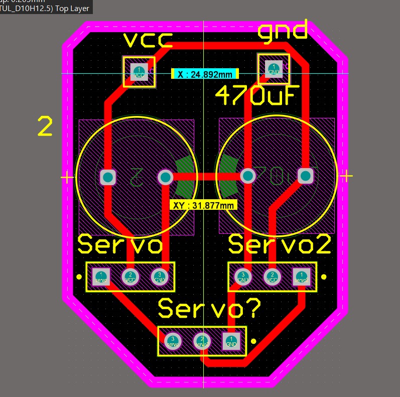
2D schematic of the servo module.
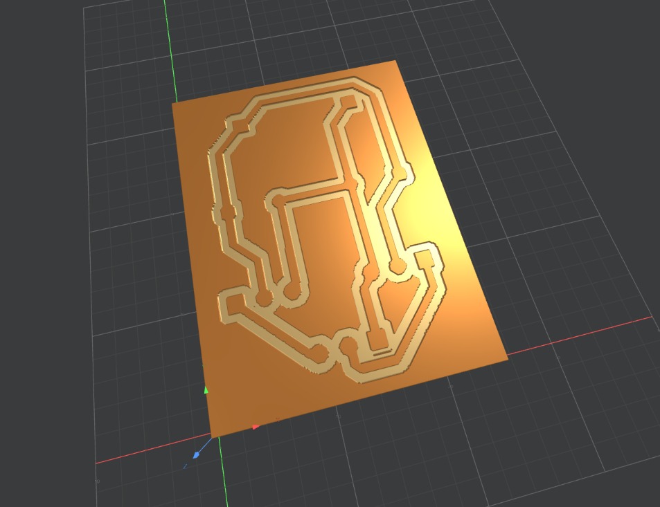
3D simulation of the final board.
Fabrication and Integration
Board Fabrication
For fabrication, I used the Roland MonoFab milling machine in my Lab. The process was clean and fast.
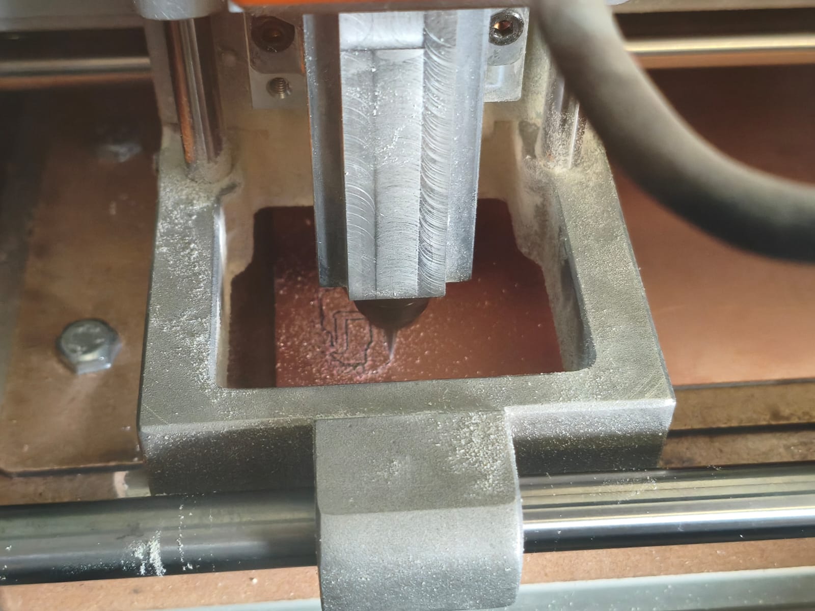
Board being milled on the Roland MonoFab.
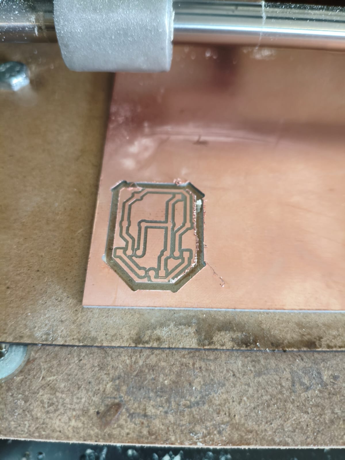
The milled auxiliary board ready for cleaning.
Soldering and Assembly
After cleaning the board with isopropyl alcohol, I soldered all the components. Because it was a simple auxiliary board, it only required header pins and the electrolytic capacitors.
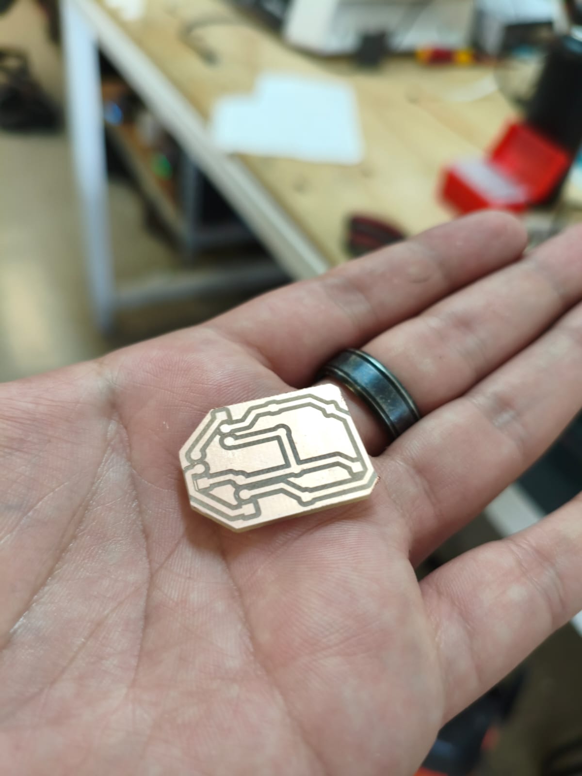
Board completely clean and ready.
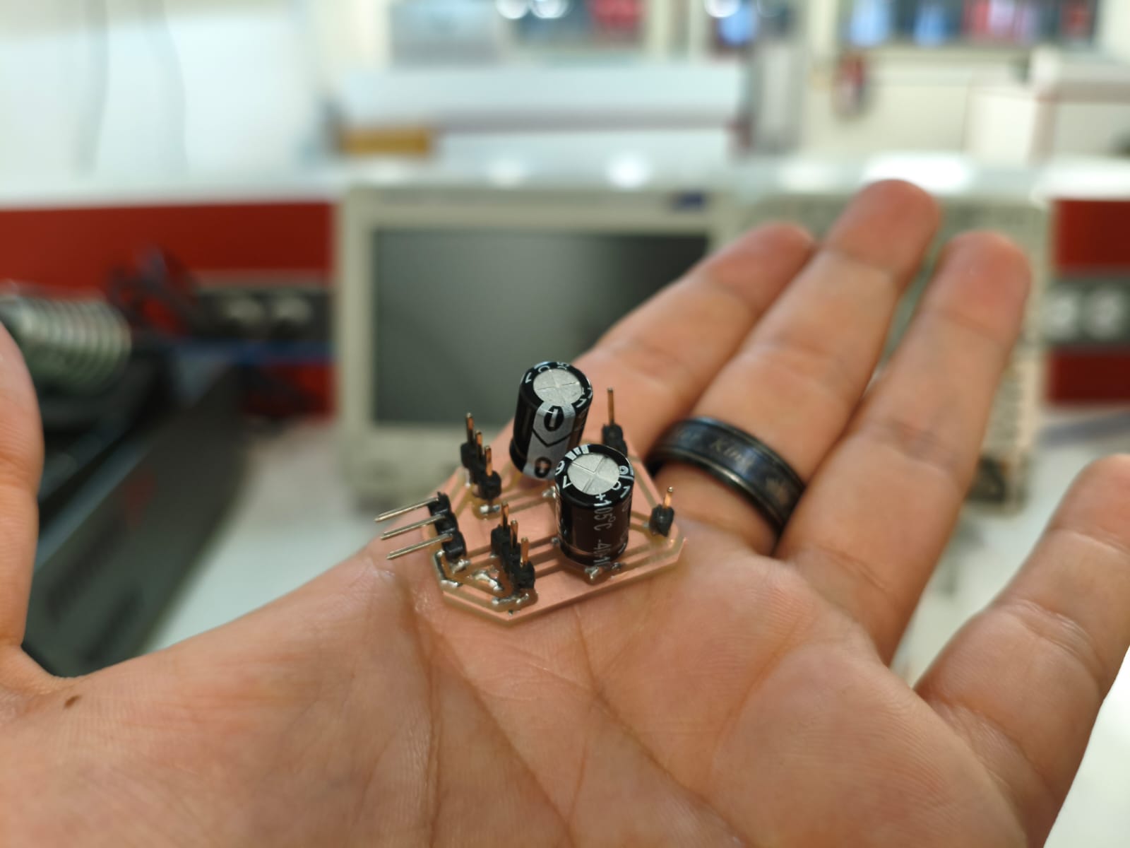
Board soldered and ready to connect.
Programming with ESP-IDF and C
The goal is simple, when pressing a button connected to the XIAO, both servos should rotate 90 degrees and 1 second later they would rotate another 90 degrees (180 degrees total), and if I press again the button, they should return to 90 and 0. For this, I used ESP-IDF with pure C.
Logic and Libraries
The key to controlling servos is generating precise PWM (Pulse Width Modulation) signals with a 50Hz frequency, because this servos work at that rate of frecuency. In ESP-IDF, this is achieved using the driver/ledc.h (LED Controller) library, which is highly versatile. We need to configure a timer to define the frequency and an output channel to define the duty cycle, which corresponds to the angle position. The program logic includes a simple state machine that toggles between two predefined duty cycle values for 0 , 90 and 180 degrees every time a button press is detected.
#include "freertos/FreeRTOS.h"
#include "freertos/task.h"
#include "driver/ledc.h"
#include "driver/gpio.h"
#include "esp_log.h"

#define SERVO1 GPIO_NUM_2
#define SERVO2 GPIO_NUM_1
#define BUTTON GPIO_NUM_19

#define TIMER LEDC_TIMER_0
#define LEDC_MODE LEDC_LOW_SPEED_MODE
#define RESOLUTION LEDC_TIMER_13_BIT
#define FRECUENCY 50

#define MOVESERVO_0 205
#define MOVESERVO_90 614
#define MOVESERVO_180 1024

const static char *TAG = "Servo-output";

void servo_init(ledc_channel_t canal, int pin_gpio) { //initializing servos
    ledc_channel_config_t configuracion_canal = {
        .speed_mode = LEDC_MODE,
        .channel = canal,
        .timer_sel = TIMER,
        .intr_type = LEDC_INTR_DISABLE,
        .gpio_num = pin_gpio,
        .duty = MOVESERVO_0,
        .hpoint = 0
    };
    ESP_ERROR_CHECK(ledc_channel_config(&configuracion_canal));
}

void move_servo(int duty, const char* position) { //function for moving servos
    ESP_LOGI(TAG, "Rotating at %s degrees...", position);
    ESP_ERROR_CHECK(ledc_set_duty(LEDC_MODE, LEDC_CHANNEL_0, duty));
    ESP_ERROR_CHECK(ledc_set_duty(LEDC_MODE, LEDC_CHANNEL_1, duty));
    ESP_ERROR_CHECK(ledc_update_duty(LEDC_MODE, LEDC_CHANNEL_0));
    ESP_ERROR_CHECK(ledc_update_duty(LEDC_MODE, LEDC_CHANNEL_1));
}

void app_main(void) {
    ledc_timer_config_t configure_timer = { //configure servos
        .speed_mode = LEDC_MODE,
        .timer_num = TIMER,
        .duty_resolution = RESOLUTION,
        .freq_hz = FRECUENCY,
        .clk_cfg = LEDC_AUTO_CLK
    };
    ESP_ERROR_CHECK(ledc_timer_config(&configure_timer));

    servo_init(LEDC_CHANNEL_0, SERVO1);
    servo_init(LEDC_CHANNEL_1, SERVO2);

    gpio_reset_pin(BUTTON);
    gpio_set_direction(BUTTON, GPIO_MODE_INPUT);
    gpio_set_pull_mode(BUTTON, GPIO_PULLUP_ONLY);

    bool previous_button_state = true;
    bool servo_in_0 = true;

    vTaskDelay(pdMS_TO_TICKS(1000));

    while (1) {
        bool current_button_state = gpio_get_level(BUTTON);

        if (previous_button_state && !current_button_state) { //logic for pressing button
            if (servo_in_0) {
                move_servo(MOVESERVO_180, "180");
                vTaskDelay(pdMS_TO_TICKS(1000));
                move_servo(MOVESERVO_90, "90");
                vTaskDelay(pdMS_TO_TICKS(1000));
                move_servo(MOVESERVO_0, "0");
            } else {
                move_servo(MOVESERVO_0, "0");
                vTaskDelay(pdMS_TO_TICKS(1000));
                move_servo(MOVESERVO_90, "90");
                vTaskDelay(pdMS_TO_TICKS(1000));
                move_servo(MOVESERVO_180, "180");
            }

            servo_in_0 = !servo_in_0;
            vTaskDelay(pdMS_TO_TICKS(300));
        }

        previous_button_state = current_button_state;
        vTaskDelay(pdMS_TO_TICKS(20));
    }
}
Final Result
Problems Found and Solutions
At first, when testing the servos, I noticed erratic movement. After reviewing the everything, I remembered the importance of power stability. I confirmed that the problem was a loose shared ground connection with the external 5V source. After securing the connection and verifying that the electrolytic capacitors were properly soldered, the system worked perfectly, proving that the XIAO can stably control servos via PWM when appropriate external power is used.
Here is a video demonstrating the operation of both servomotors rotating 90 degrees when the button is pressed and returning to 0 degrees on the next press.
Final demonstration of the working system.
Files
Here you can download the original files generated for this week's project: