

Week 09
Input Devices
Check out our Group Assignment to see how we explored different sensors and inputs, including measurements with a multimeter and an oscilloscope GROUP PAGE →
// MAIN OBJECTIVE \\
Measure something: add a sensor to a microcontroller board that you have designed and read it.
The Magic of Sensors
In my opinion, I really like the different types of sensors because they are how computers can see and feel the physical world. The logic of a sensor is fascinating: it reads data from the environment, transmits those values as bits, and the microcontroller interprets and prints them for monitoring or control.
For this week, I will be using different sensors. Two of them share the same fundamental operating concept, which is the increase or variation of electrical resistance due to deformation and pressure exerted on a special material. The other sensor I will use is completely different, as it is responsible for measuring position and acceleration in real time.
Flexible & Pressure Sensors: Working with Velostat
As I mentioned, the first two sensors use the same logic and manufacturing method, but have different uses and applications: one will act as a flexible sensor that detects bending, and the other will detect direct pressure. All this is possible thanks to an incredible material called Velostat.
What is Velostat?
It is a conductive and flexible polymeric plastic sheet, mainly used to create custom pressure and force sensors in electronics and wearable technology. Its main characteristic is that its electrical resistance decreases when pressure is applied or when it is bent, making it ideal for creating tactile switches or sensors.
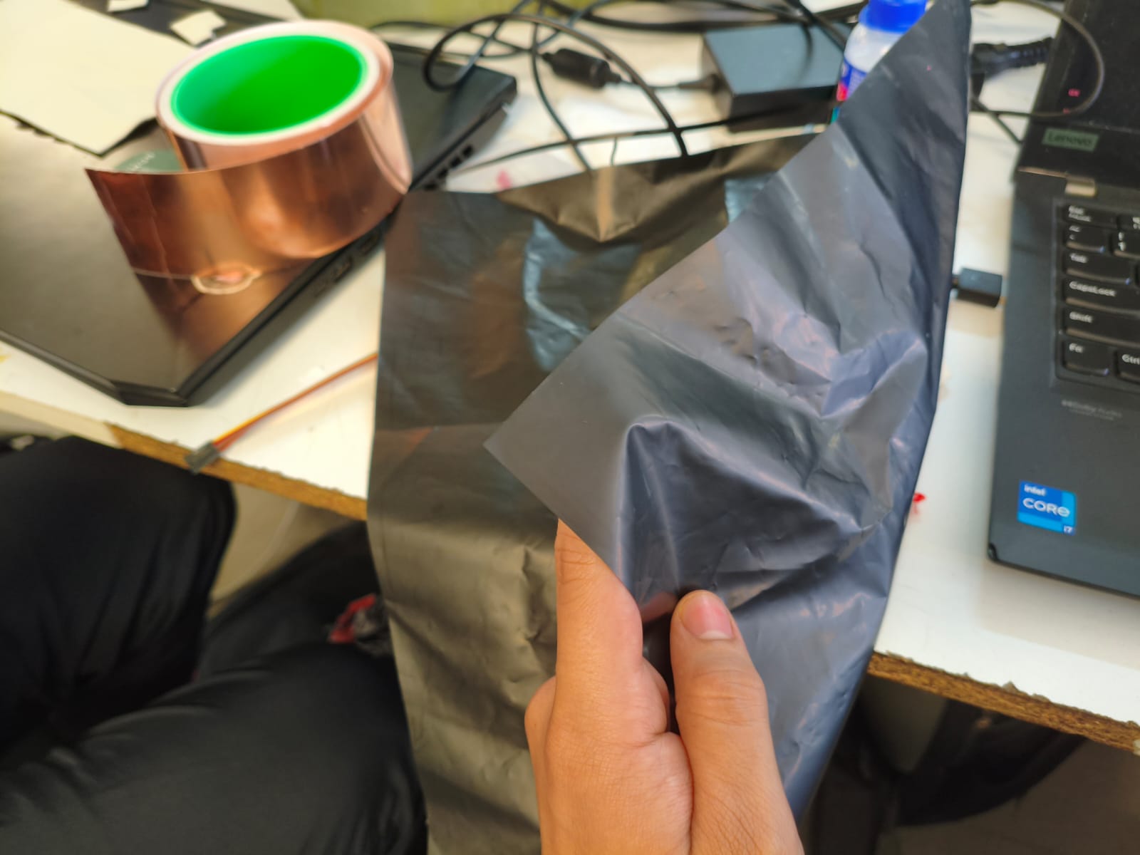
This is a Velostat sheet.
Building a Wearable Sensor
The Basic Configuration
First we need to replicate the most basic setup. This consists of placing crossed or overlapping conductive wires or threads between layers, leaving the Velostat in the middle, like a sandwich. In this way, when pressure is applied, the circuit interacts with the variable resistance of the material.
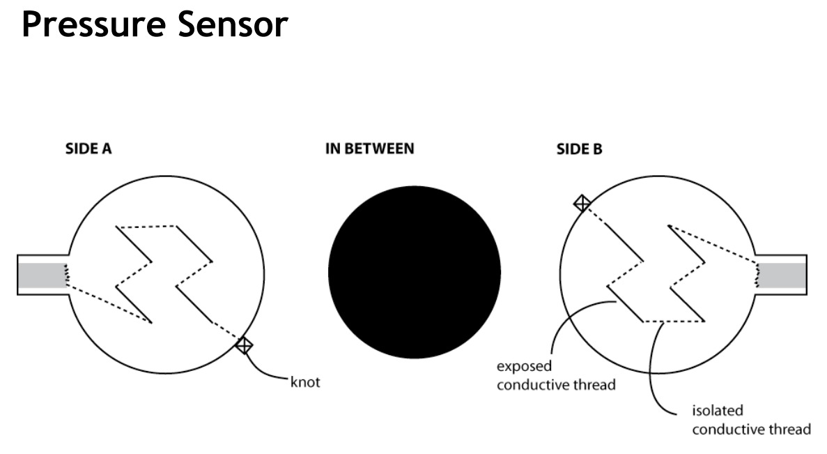
Example of the ideal configuration for the pressure/flex sensor matrix.
Having the two conductive plates or terminals, they are joined so that, either by pressure or bending, the circuit is "squashed". This squashing generates the signal variation that our microcontroller can read.
My Implementation: The Smart Glove
Now having the base and theory clear, it was my turn to do it. Below, I show the materials I used to manufacture my smart glove:
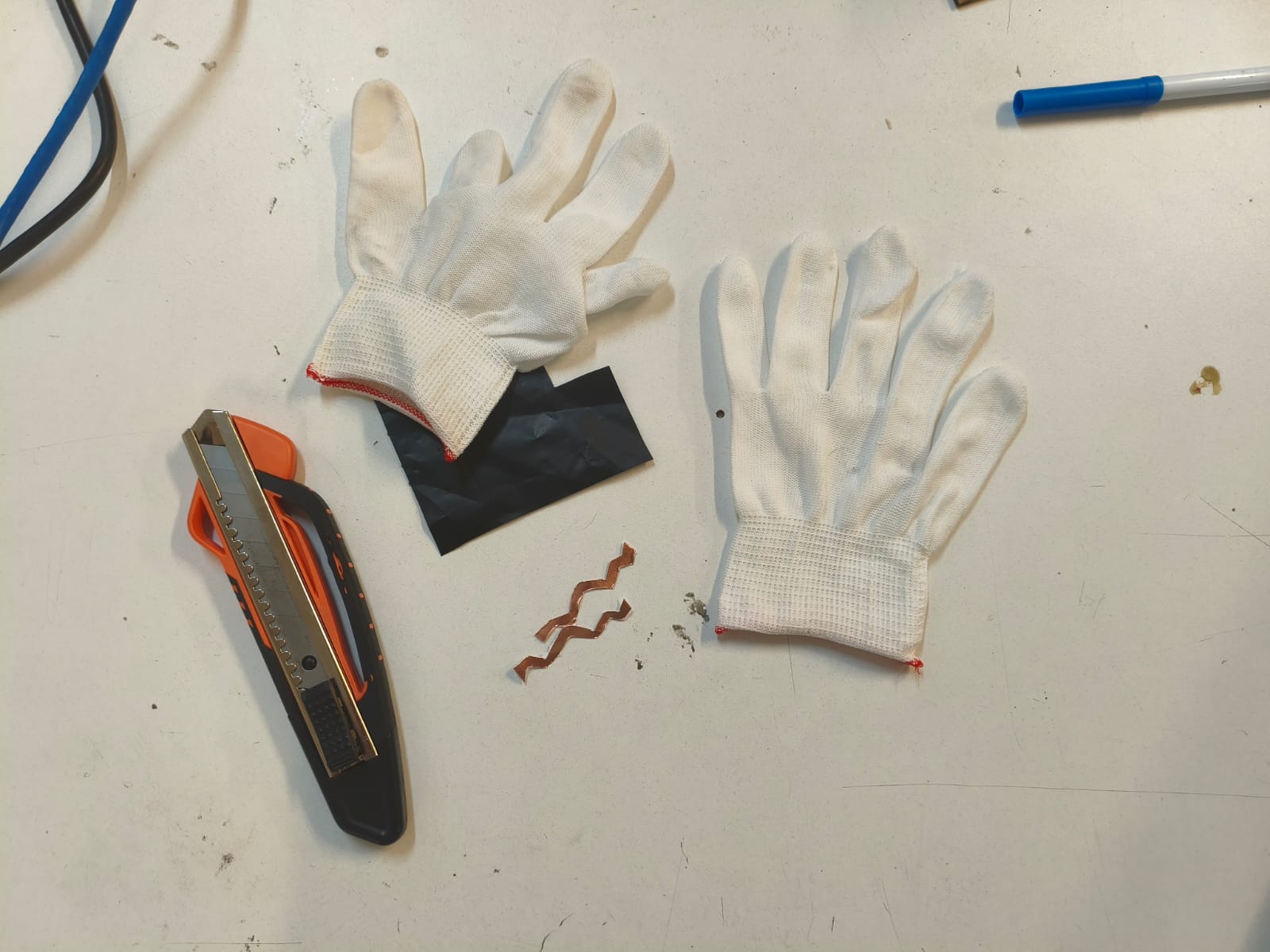
Materials used for the construction of the glove.
Fabrication Process
In the following video, I show a timelapse of how I created the sensors and assembled them step by step on the fabric glove.
Timelapse of the creation and integration process into the fabric.
Manufacturing objectives
The final result consists of two different applications of the same principle integrated into the hand: a pressure button located on the tip of the thumb and a flexible strip located along the middle finger.
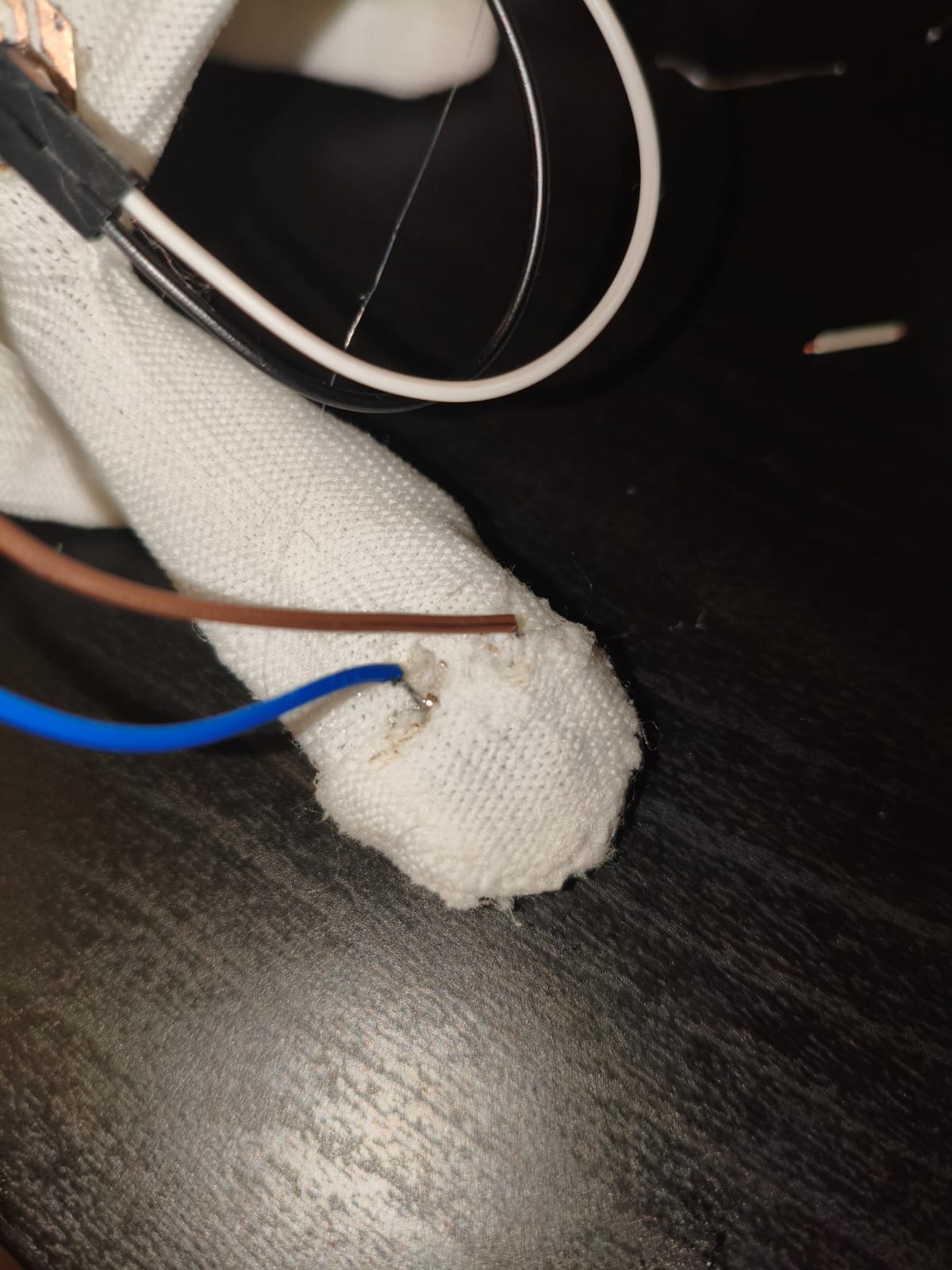
Pressure sensor implemented on the thumb.
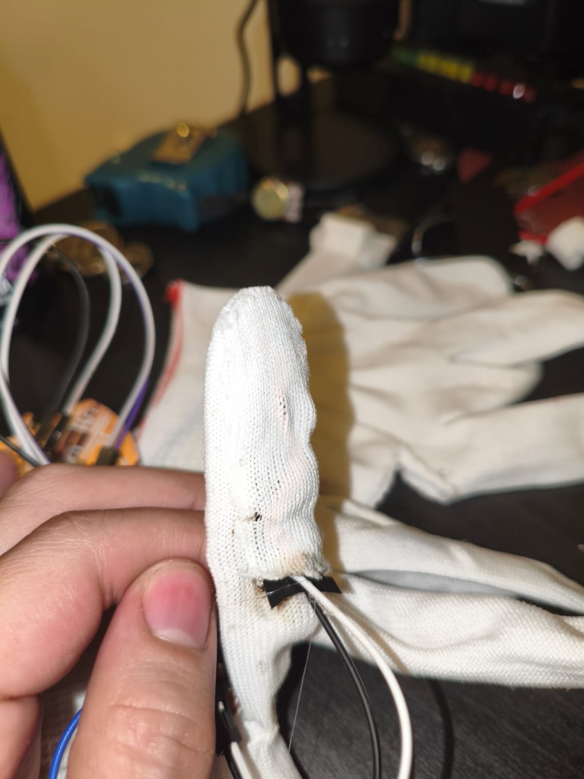
Flex sensor implemented along the index finger.
The Third Sensor: Inertial Measurement with Gyroscopes
The third sensor I am incorporating is a gyroscope (often packaged as an Inertial Measurement Unit, or IMU, alongside an accelerometer). A gyroscope measures the rate of rotation around a particular axis. In everyday life, they are incredibly common, for example, they are what allow your smartphone to know when you rotate the screen, enable motion tracking in VR headsets, and provide stabilization in cameras and modern vehicles.
Selecting the type of IMU
When looking for an IMU for common electronics projects, the MPU6050 is usually the most used choice. It is widely documented and easy to find, but it tends to be quite noisy and sometimes struggles with data drift over time.
For my personal project, I needed something more reliable, so I opted for the BMI160. The main reason for this choice is its superior noise filtering capabilities and lower power consumption. When controlling a robot, it's fast and precise orientation data is critical; the BMI160 provides cleaner data, allowing the control loops to react accurately without being overwhelmed by sensor noise.
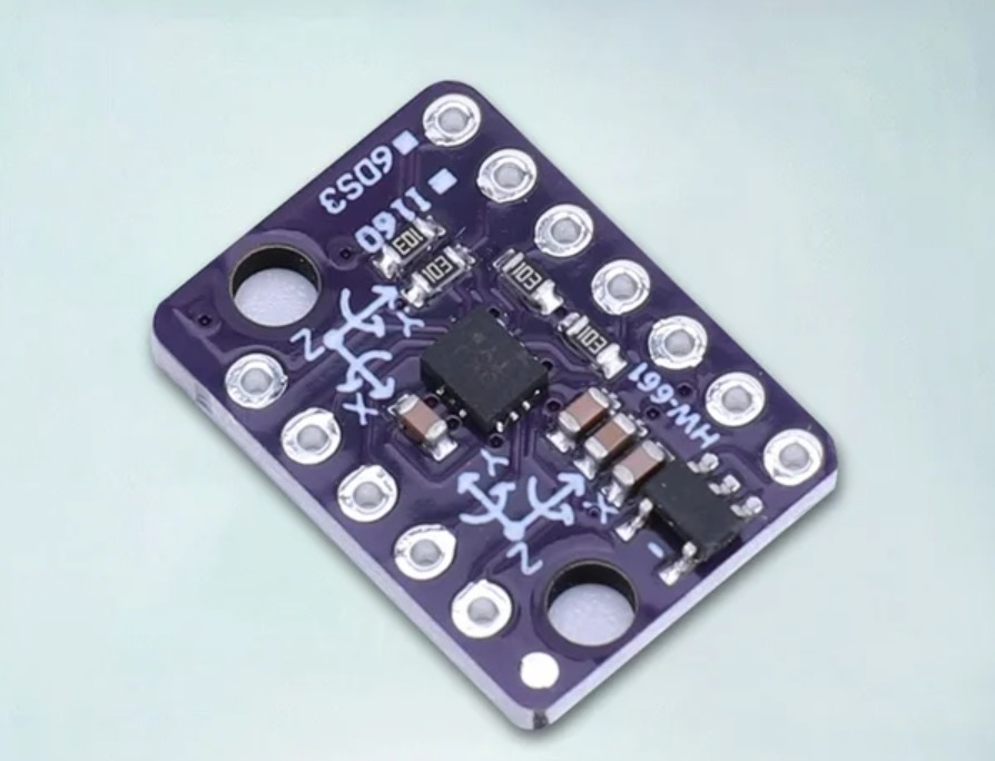
The BMI160 6-axis IMU sensor.
Communication: How I2C Works
The BMI160 communicates with the microcontroller via the I2C (Inter-Integrated Circuit) protocol, utilizing just two wires: SCL (Serial Clock) and SDA (Serial Data). The microcontroller acts as the master, generating the clock signal on the SCL , while the SDA line is used to send and receive the actual data bits.
This protocol is highly useful for this application because it allows fast, reliable communication using minimal pins. The microcontroller can rapidly query the BMI160's registers, read the raw X, Y, and Z acceleration and gyro values, and interpret them in real-time to monitor or adjust the drone's position in the air.
Hardware Integration and Stability
A crucial aspect of working with IMUs in a high-movement environment is mechanical stability. The BMI160 is perfectly soldered directly onto my custom PCB. A rigid, secure solder connection ensures that the high-frequency vibrations generated by the drone's motors and propellers do not introduce mechanical noise or false readings into the sensor. If the connection were loose, the vibration would render the flight data completely useless.
Sensor Implementation & Hardware Setup
Initial Configuration & Components
To implement these sensors, I first needed to define the hardware architecture. The core of this setup is the Seeed Studio XIAO ESP32-C3 microcontroller, which is compact and powerful enough for reading inputs and handling future wireless communication.
Alongside the three main sensors, I am using two 10KΩ resistors. These resistors are essential for creating a voltage divider circuit with the Velostat sensors, allowing the microcontroller to detect the changes in resistance as readable variations in voltage.
The Main PCB
For the main controller, I am reusing my PCB that I fabricated during Week 08 (Electronics Production), which is shaped like the Death Star from Star Wars. I took the opportunity to re-solder some of the components to make it look much cleaner and more aesthetically pleasing for this integration.
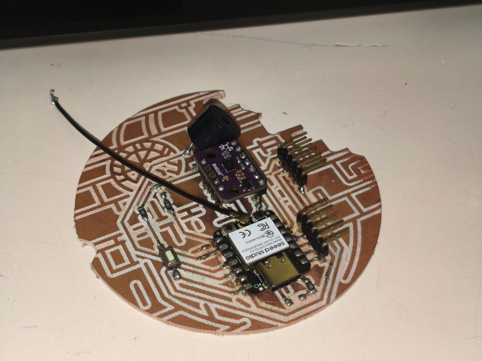
The re-soldered Death Star main board.
Designing the Glove PCB
To handle the wearable sensors on the glove, I needed to design an external, secondary PCB. This board is crucial because, in the future, it will handle the wireless communication needed to send signals directly from my hand to the drone. I designed this custom board using Altium Designer.
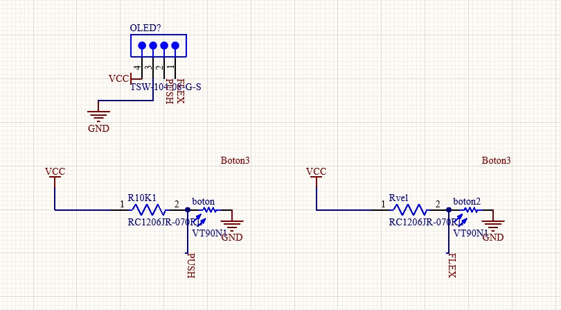
2D schematic design in Altium Designer.
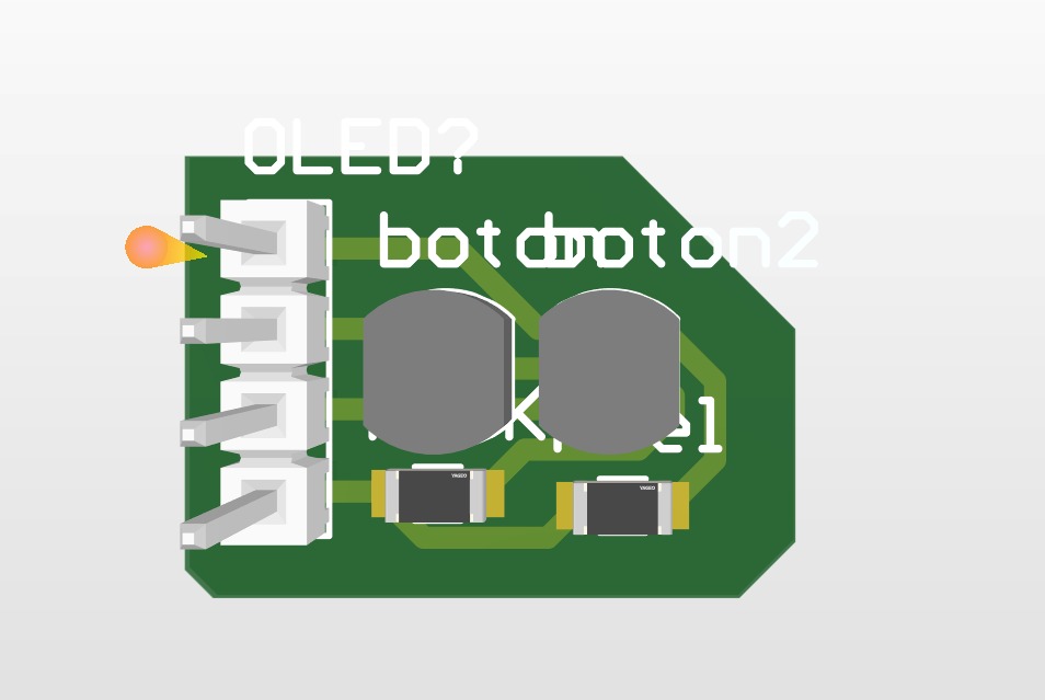
3D simulation of the final board.
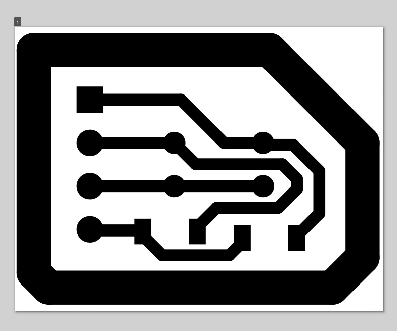
Exported PDF ready for the milling process.
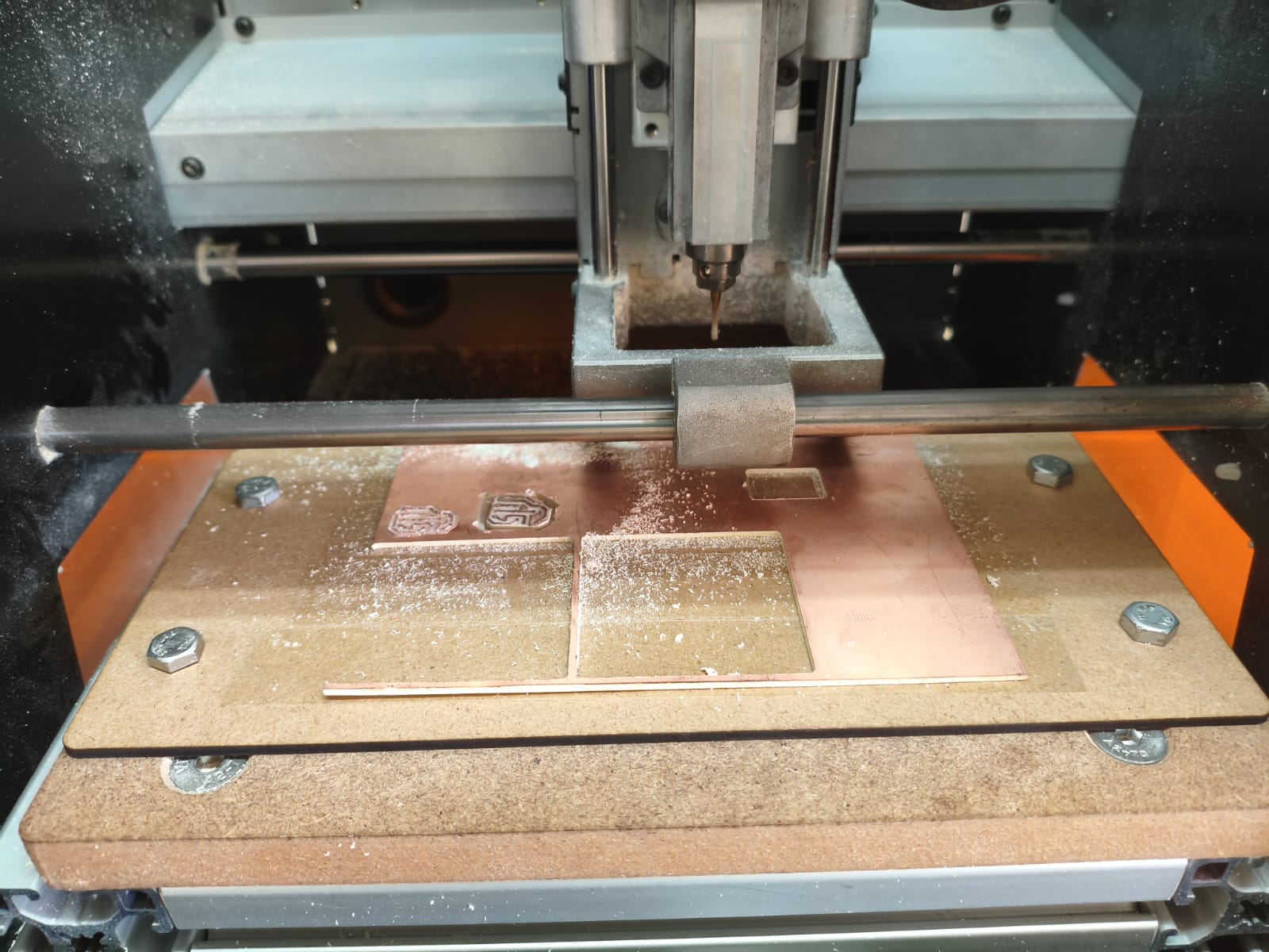
Cutting and milling the PCB.

The resulting board after cleaning.
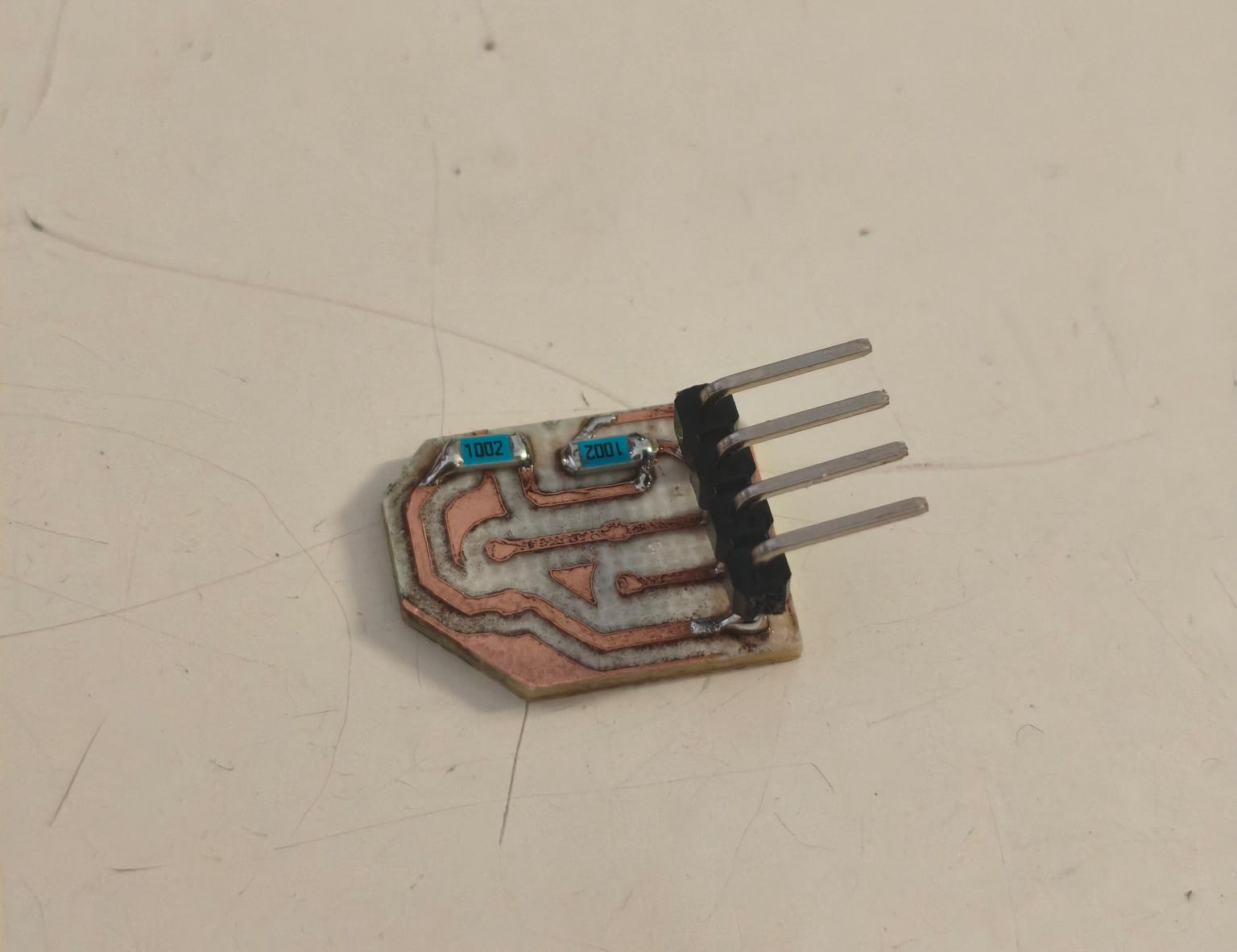
6. Final result with the 10K resistors soldered, ready for the sensors.
Wiring and Connections
With the boards ready, it was time to wire everything up. I connected the new Glove PCB to the XIAO ESP32-C3. The wearable sensors were connected to analog pins 7 and 8 respectively, along with a shared GND connection.
For the BMI160 gyroscope, I connected its SDA and SCL pins to the corresponding I2C pins on the XIAO, ensuring it shared the proper power and ground lines for stable communication.
Timelapse of wiring and assembling all the components together.
Testing the Sensors
Before creating complex logic, it is mandatory to test if the sensors are working. To measure the raw values of the sensors, a simple test program must be written to read the raw data directly from the pins and print it to the serial monitor.
Velostat Sensors Raw Test
This code reads the raw analog values from the Velostat button and flex sensor.
#include
#include "freertos/FreeRTOS.h"
#include "freertos/task.h"
#include "esp_adc/adc_oneshot.h"
#include "esp_log.h"

const static char *TAG = "LECTURA_A0";

void app_main(void)
{
    adc_oneshot_unit_handle_t adc1_handle;
    adc_oneshot_unit_init_cfg_t init_config1 = {
        .unit_id = ADC_UNIT_1,
    };
    ESP_ERROR_CHECK(adc_oneshot_new_unit(&init_config1, &adc1_handle));


    adc_oneshot_chan_cfg_t config = {
        .bitwidth = ADC_BITWIDTH_DEFAULT,
        .atten = ADC_ATTEN_DB_12,
    };
    ESP_ERROR_CHECK(adc_oneshot_config_channel(adc1_handle, ADC_CHANNEL_2, &config));

    while (1) {
        int pot_raw_value;

        ESP_ERROR_CHECK(adc_oneshot_read(adc1_handle, ADC_CHANNEL_2, &pot_raw_value));

        ESP_LOGI(TAG, "Valor en A0 (bits): %d", pot_raw_value);


        vTaskDelay(pdMS_TO_TICKS(300));
    }
}
BMI160 Gyroscope Raw Test
This code establishes I2C communication and reads the raw X, Y, and Z values from the gyroscope.
    #include
#include "freertos/FreeRTOS.h"
#include "freertos/task.h"
#include "driver/i2c.h"
#include "esp_err.h"

#define I2C_MASTER_SCL_IO           7
#define I2C_MASTER_SDA_IO           6
#define I2C_MASTER_NUM              0
#define I2C_MASTER_FREQ_HZ          100000
#define I2C_MASTER_TX_BUF_DISABLE   0
#define I2C_MASTER_RX_BUF_DISABLE   0
#define SENSOR_ADDR                 0x68

static esp_err_t i2c_master_init(void)
{
    i2c_config_t conf = {
        .mode = I2C_MODE_MASTER,
        .sda_io_num = I2C_MASTER_SDA_IO,
        .scl_io_num = I2C_MASTER_SCL_IO,
        .sda_pullup_en = GPIO_PULLUP_ENABLE,
        .scl_pullup_en = GPIO_PULLUP_ENABLE,
        .master.clk_speed = I2C_MASTER_FREQ_HZ,
    };

    i2c_param_config(I2C_MASTER_NUM, &conf);
    return i2c_driver_install(I2C_MASTER_NUM, conf.mode, I2C_MASTER_RX_BUF_DISABLE, I2C_MASTER_TX_BUF_DISABLE, 0);
}

void app_main(void)
{
    ESP_ERROR_CHECK(i2c_master_init());

    uint8_t cmd_reg = 0x7E;
    uint8_t cmd_val = 0x11;
    uint8_t write_buf[2] = {cmd_reg, cmd_val};

    i2c_master_write_to_device(I2C_MASTER_NUM, SENSOR_ADDR, write_buf, 2, 1000 / portTICK_PERIOD_MS);

    vTaskDelay(50 / portTICK_PERIOD_MS);

    uint8_t reg = 0x12;
    uint8_t memoria[6];

    while (1) {
        esp_err_t err = i2c_master_write_read_device(I2C_MASTER_NUM, SENSOR_ADDR, ®, 1, memoria, 6, 1000 / portTICK_PERIOD_MS);

        if (err == ESP_OK) {
            int16_t accel_x_raw = (memoria[1] << 8) | memoria[0];
            int16_t accel_y_raw = (memoria[3] << 8) | memoria[2];
            int16_t accel_z_raw = (memoria[5] << 8) | memoria[4];

            float g_x = accel_x_raw / 16384.0f;
            float g_y = accel_y_raw / 16384.0f;
            float g_z = accel_z_raw / 16384.0f;

            printf("X: %.2f G \t Y: %.2f G \t Z: %.2f G\n", g_x, g_y, g_z);
        } else {
            printf("I2C error (ret=%d)\n", err);
        }

        vTaskDelay(100 / portTICK_PERIOD_MS);
    }
}
Raw Testing Video
Demonstration of the serial monitor reading raw values from the velostat sensors.
Demonstration of the serial monitor reading raw values from the gyroscope.
Data Processing & Logic
Reading raw values is great, but making those values do something useful is the real goal. Using programming and some simple mathematical logic, I mapped the sensor data to control physical outputs.
1. The Velostat Button (Heartbeat Toggle)
I programmed a simple toggle state machine. When the analog reading drops below a certain threshold, meaning the finger pressed the button, the system switches its state from OFF to ON. When it is ON, it triggers a buzzer to play a "heartbeat" pattern. Pressing the button again switches the state back to OFF, muting the buzzer.
2. The Flex Sensor (LED Brightness)
To control an LED smoothly with the finger's bending motion, I used a linear mapping function. The formula is essentially:
MappedValue = (CurrentValue - MinRead) * (MaxOut - MinOut) / (MaxRead - MinRead)
In simple terms: when my finger is fully stretched, the sensor reads a high value, which maps to minimum brightness (0%). When I bend my finger, the resistance drops, and the code linearly maps that lower value to maximum brightness (100%).
Final Integrated Code & Result
Here is the final main code integrating all the logic described above:
#include
#include
#include "freertos/FreeRTOS.h"
#include "freertos/task.h"
#include "esp_adc/adc_oneshot.h"
#include "driver/ledc.h"
#include "driver/gpio.h"
#include "esp_log.h"

const static char *TAG = "INVERTED_SYSTEM";

#define SENSOR_POT_CANAL    ADC_CHANNEL_2
#define SENSOR_VELO_CANAL   ADC_CHANNEL_3
#define LED_PIN             20
#define BUZZER_PIN          GPIO_NUM_10

#define LEDC_TIMER          LEDC_TIMER_0
#define LEDC_MODE           LEDC_LOW_SPEED_MODE
#define LEDC_CHANNEL        LEDC_CHANNEL_0
#define LEDC_DUTY_RES       LEDC_TIMER_12_BIT
#define LEDC_FREQUENCY      5000

long map_val(long x, long in_min, long in_max, long out_min, long out_max) {
    if (x <= in_min) return out_min;
    if (x >= in_max) return out_max;
    return (x - in_min) * (out_max - out_min) / (in_max - in_min) + out_min;
}

void task_velostat_led(void *arg) {
    adc_oneshot_unit_handle_t adc_handle = (adc_oneshot_unit_handle_t)arg;
    int velo_val;

    while (1) {
        ESP_ERROR_CHECK(adc_oneshot_read(adc_handle, SENSOR_VELO_CANAL, &velo_val));

        int pwm_duty = map_val(velo_val, 1500, 3000, 0, 4095);

        ESP_ERROR_CHECK(ledc_set_duty(LEDC_MODE, LEDC_CHANNEL, pwm_duty));
        ESP_ERROR_CHECK(ledc_update_duty(LEDC_MODE, LEDC_CHANNEL));

        vTaskDelay(pdMS_TO_TICKS(50));
    }
}

void task_velostat_button_buzzer(void *arg) {
    adc_oneshot_unit_handle_t adc_handle = (adc_oneshot_unit_handle_t)arg;
    int velo_button_val;

    bool buzzer_active = false;
    bool last_button_state = false;
    int tick_count = 0;
    int PRESSURE_THRESHOLD = 300;

    while (1) {
        ESP_ERROR_CHECK(adc_oneshot_read(adc_handle, SENSOR_POT_CANAL, &velo_button_val));

        ESP_LOGW("DEBUG_VELOSTAT", "Raw value: %d", velo_button_val);

        bool current_button_state = (velo_button_val > PRESSURE_THRESHOLD);

        if (current_button_state && !last_button_state) {
            buzzer_active = !buzzer_active;
            ESP_LOGI(TAG, "Heartbeat toggled. State: %d", buzzer_active);
            vTaskDelay(pdMS_TO_TICKS(250));
        }
        last_button_state = current_button_state;

        if (buzzer_active) {
            tick_count = (tick_count + 1) % 20;
            if (tick_count < 2 || (tick_count >= 4 && tick_count < 6)) {
                gpio_set_level(BUZZER_PIN, 1);
            } else {
                gpio_set_level(BUZZER_PIN, 0);
            }
        } else {
            gpio_set_level(BUZZER_PIN, 0);
            tick_count = 0;
        }

        vTaskDelay(pdMS_TO_TICKS(100));
    }
}

void app_main(void) {
    adc_oneshot_unit_handle_t adc1_handle;
    adc_oneshot_unit_init_cfg_t init_config = { .unit_id = ADC_UNIT_1 };
    ESP_ERROR_CHECK(adc_oneshot_new_unit(&init_config, &adc1_handle));

    adc_oneshot_chan_cfg_t adc_config = {
        .bitwidth = ADC_BITWIDTH_DEFAULT,
        .atten = ADC_ATTEN_DB_12,
    };
    ESP_ERROR_CHECK(adc_oneshot_config_channel(adc1_handle, SENSOR_POT_CANAL, &adc_config));
    ESP_ERROR_CHECK(adc_oneshot_config_channel(adc1_handle, SENSOR_VELO_CANAL, &adc_config));

    ledc_timer_config_t ledc_timer = {
        .speed_mode = LEDC_MODE, .timer_num = LEDC_TIMER,
        .duty_resolution = LEDC_DUTY_RES, .freq_hz = LEDC_FREQUENCY,
        .clk_cfg = LEDC_AUTO_CLK
    };
    ESP_ERROR_CHECK(ledc_timer_config(&ledc_timer));

    ledc_channel_config_t ledc_channel = {
        .speed_mode = LEDC_MODE, .channel = LEDC_CHANNEL,
        .timer_sel = LEDC_TIMER, .intr_type = LEDC_INTR_DISABLE,
        .gpio_num = LED_PIN, .duty = 0, .hpoint = 0
    };
    ESP_ERROR_CHECK(ledc_channel_config(&ledc_channel));

    gpio_reset_pin(BUZZER_PIN);
    gpio_set_direction(BUZZER_PIN, GPIO_MODE_OUTPUT);
    gpio_set_level(BUZZER_PIN, 0);

    xTaskCreate(task_velostat_led, "Task_Velo_LED", 2048, adc1_handle, 5, NULL);
    xTaskCreate(task_velostat_button_buzzer, "Task_Pot_Buzzer", 2048, adc1_handle, 5, NULL);
}
Final Working Prototype
Below is the video showing everything working together: the heartbeat buzzer toggling, the LED dimming as I bend my finger, and the IMU calculating angles.
Conclusion
I really enjoyed this week's assignment. Understanding how to acquire physical data, filter it, and translate it into actionable logic is incredibly satisfying. I am going to apply everything I learned here directly to my final project; the principles of I2C communication, sensor noise filtering, and custom PCB integration will be vital for making my drone fly reliably.
Files
Here you can download the original files generated for this week's project: