00. SYSTEM OVERVIEW
Individual Assignment:
Design and document the system integration for your final project.
For the SCORE project, system integration means visualizing and planning exactly how the mechanical parts, the 3D-printed housings, and the electronics will fit together in the physical world. This week is dedicated to establishing the placement of all components on the goal frame and ensuring they can be securely assembled. The central processing unit (XIAO ESP32-C6) will manage the inputs from the distance sensors and interface seamlessly with the digital application.
01. STRUCTURAL DESIGN & PLACEMENT
To visualize how the SCORE system comes together, I modeled the full training goal structure in 3DEXPERIENCE SOLIDWORKS. The physical frame is built using PVC pipes to keep it lightweight but sturdy. To protect the electronics from high-speed ball impacts, all the sensor cables are routed safely inside the PVC tubes, keeping them completely hidden. Additionally, the custom joints connecting the posts and the crossbar are 3D printed in PLA, ensuring a perfect, customized fit.
Mathematical Sensor Placement
The Time-of-Flight logic requires highly precise spacing. The front and back sensor arrays are separated by exactly 30 cm horizontally. Vertically, the sensors are spaced 21 cm apart. Since a standard size 5 football has a diameter of 22 cm, this mathematical arrangement guarantees that any shot entering the goal will break at least one laser beam, making blind spots physically impossible.
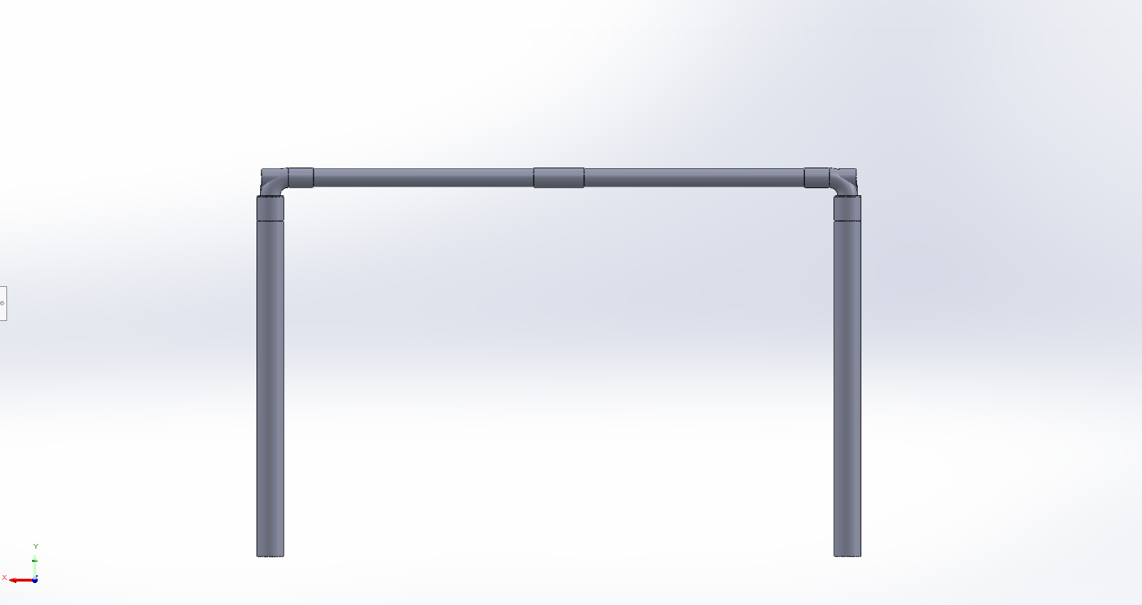
VIEW 01: FRONT PLACEMENT
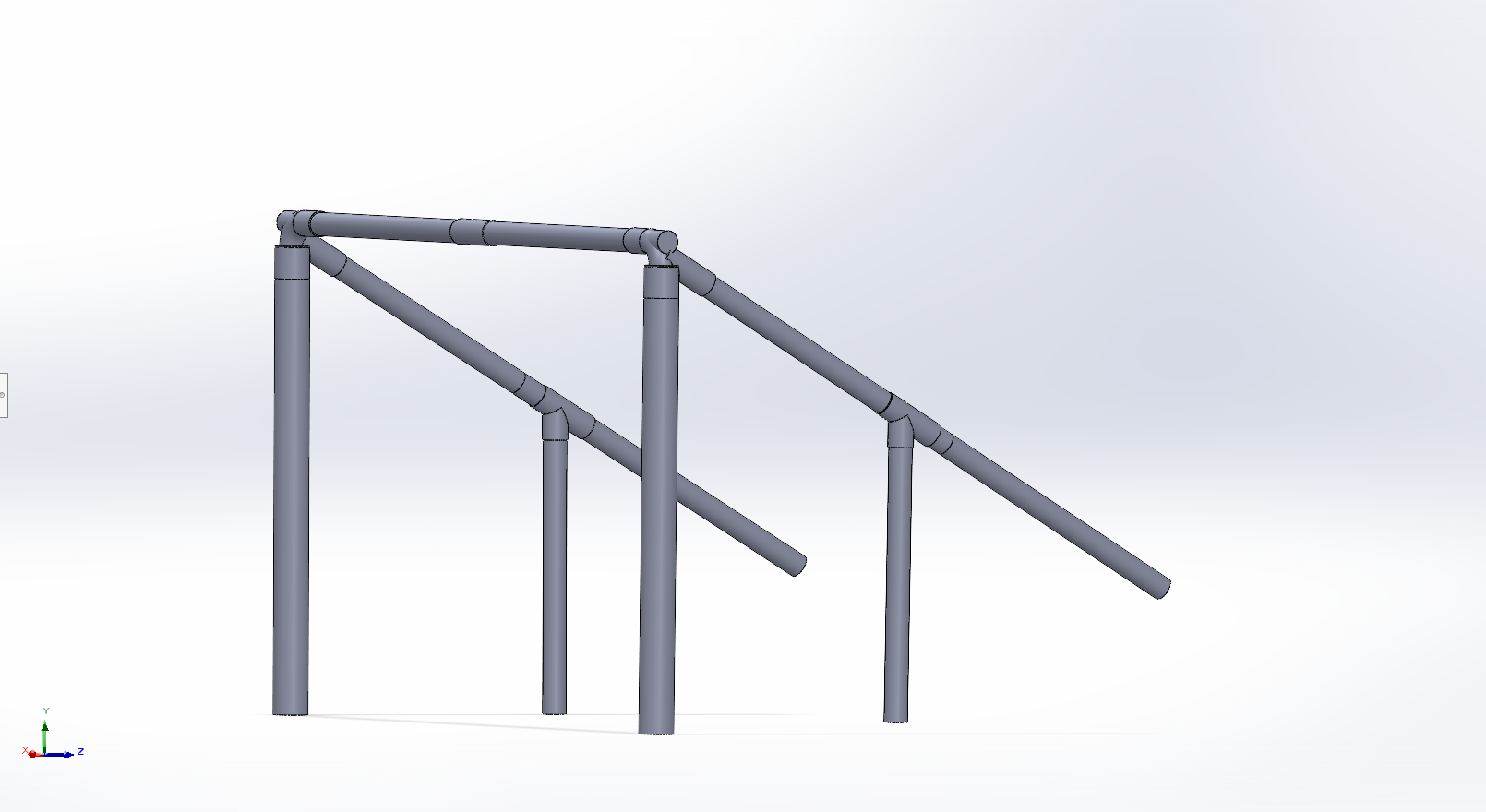
VIEW 02: SIDE ANGLE & 30CM DEPTH
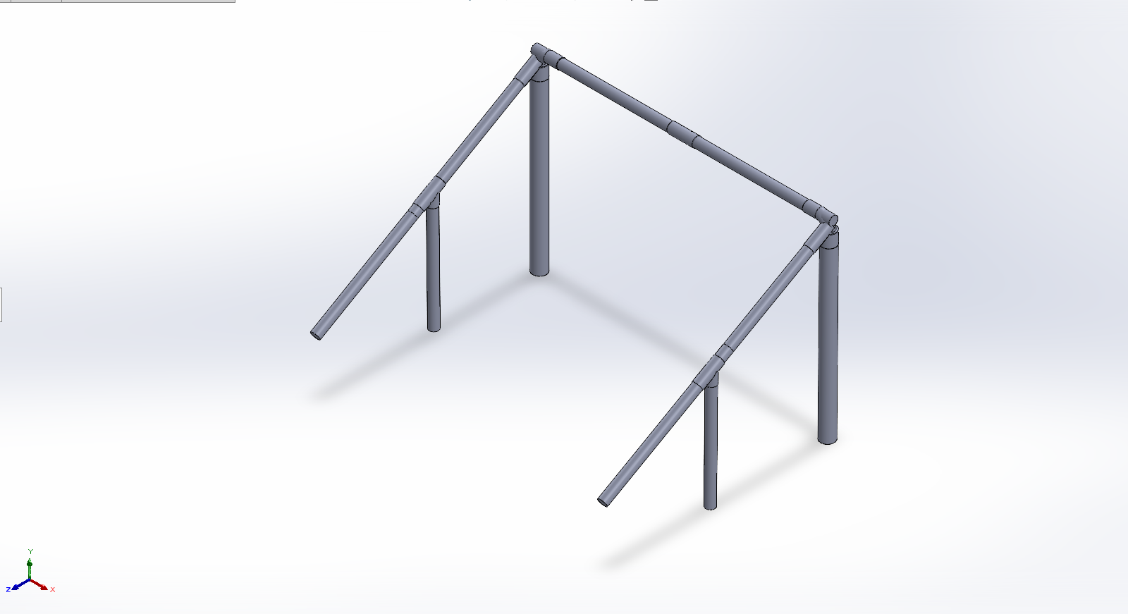
VIEW 03: ISOMETRIC OVERVIEW
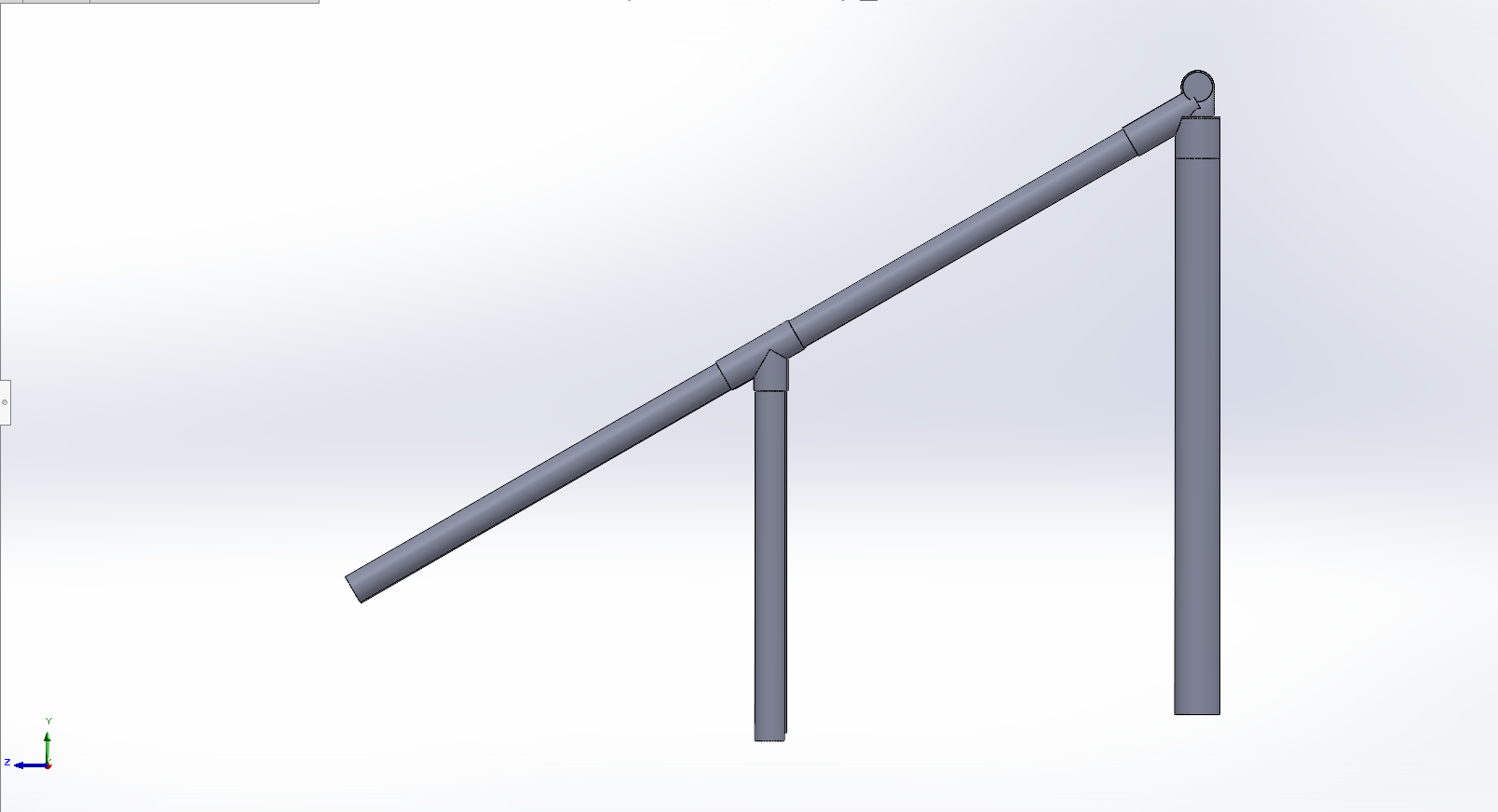
VIEW 04: 21CM VERTICAL SPACING
02. SENSORS & HOUSINGS
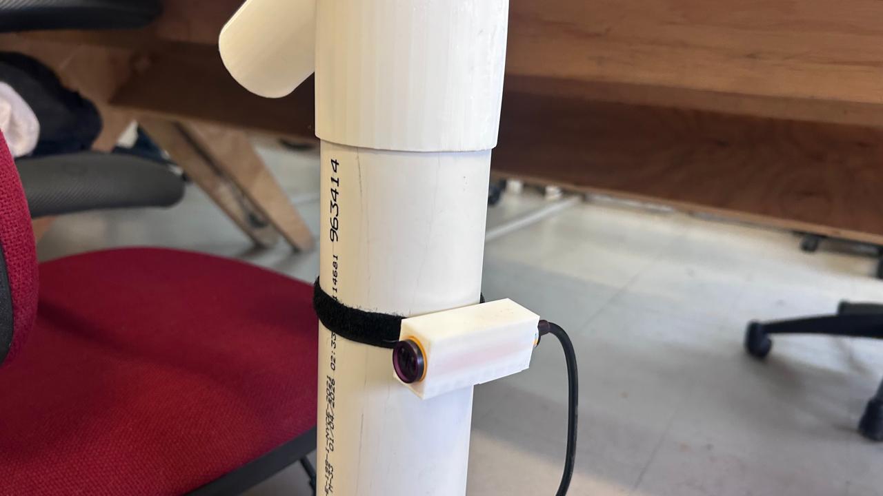
The hardware layer requires robust protection against high-speed impacts. I designed custom cases 3D-printed in PLA to house the E18-D80NK infrared sensors and their respective custom PCBs securely. These mounts ensure perfect optical alignment while absorbing shocks during gameplay.
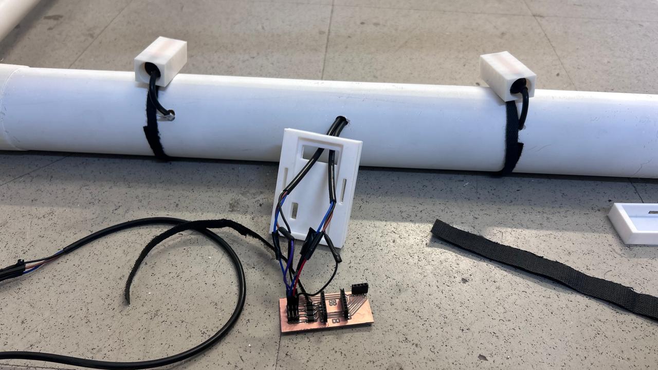
To attach the housings to the frame without permanently modifying or drilling into the PVC, they are fastened tightly around the posts using heavy-duty Velcro straps. This allows for a modular setup that is easy to assemble, adjust, and tear down.
Wireless Post-to-Post Integration: Running physical cables across the entire 1.6-meter crossbar is highly impractical and prone to wire breakage from ball impacts. To solve this, the sensor logic boards communicate with the main XIAO ESP32-C6 hub on the opposite post wirelessly. I am using the ESP-NOW protocol for this connection. ESP-NOW provides an ultra-low latency, peer-to-peer transmission that is perfect for instant speed trap calculations without relying on an external Wi-Fi router.
PLA SENSOR HOUSING
PLA PCB HOUSING
PCB HOUSING (DIGITAL RENDERS)
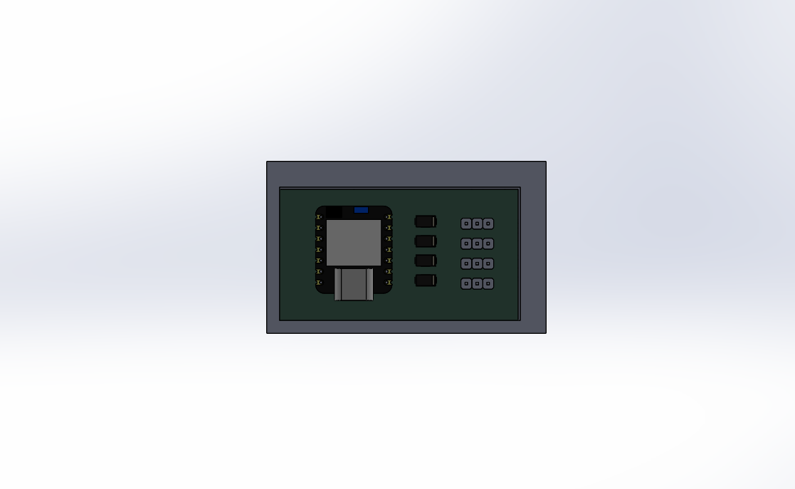
01 | TOP VIEW
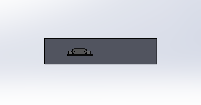
02 | INTERNAL CLEARANCE
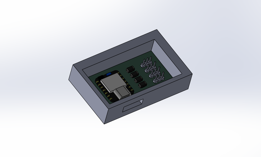
03 | ASSEMBLED
03. ASSEMBLY WORKFLOW
The physical integration follows a strict bottom-up approach to ensure no component is damaged during the final mounting process:
Step 1: Structural Setup
Assembling the PVC base frame and vertical posts using the 3D-printed PLA joints. Ensuring all connections are perfectly square so the sensors will align correctly.
Step 2: Sensor Mounting & Wiring
Inserting the optical sensors into their PLA housings. Running the cables inside the PVC tubes, and finally attaching the housings to the goal posts using Velcro straps at the pre-calculated 21 cm intervals.
Step 3: Central Hub Integration
Securing the custom PCB and the microcontroller inside the main control box. Because of the ESP-NOW protocol, physical cable routing is minimized strictly to each post's local sensors, finalizing the hardware integration.