Week 3: Computer Controlling Cutting
Parametric design
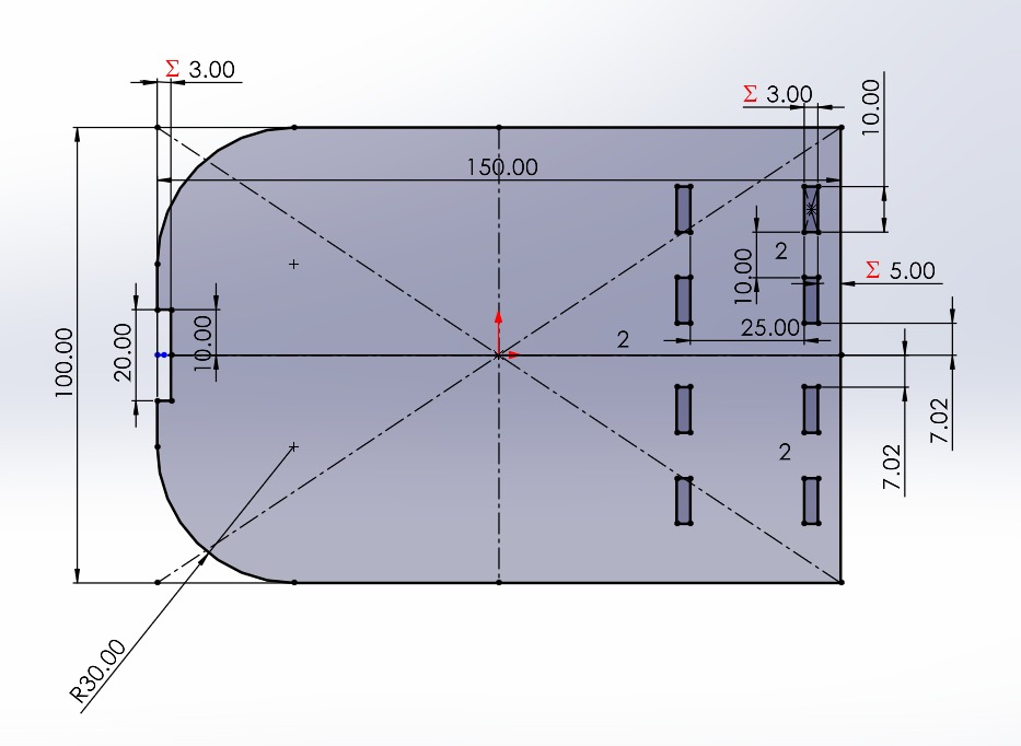
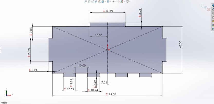
Parametric design is an algorithm-based methodology in architecture and engineering that uses parameters and rules to define, relate, and manipulate design elements, enabling the rapid generation of complex, flexible, and optimized shapes.
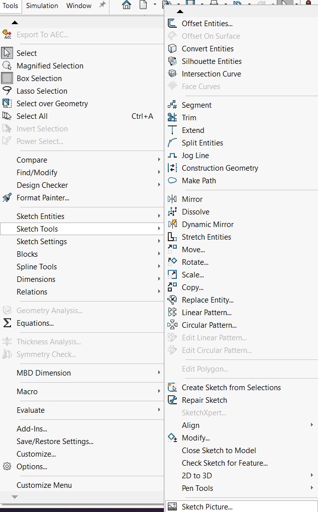
How to use Equations
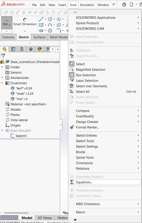
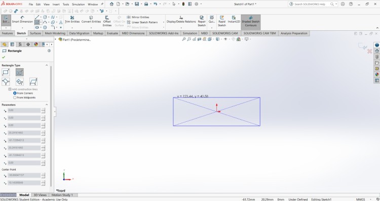
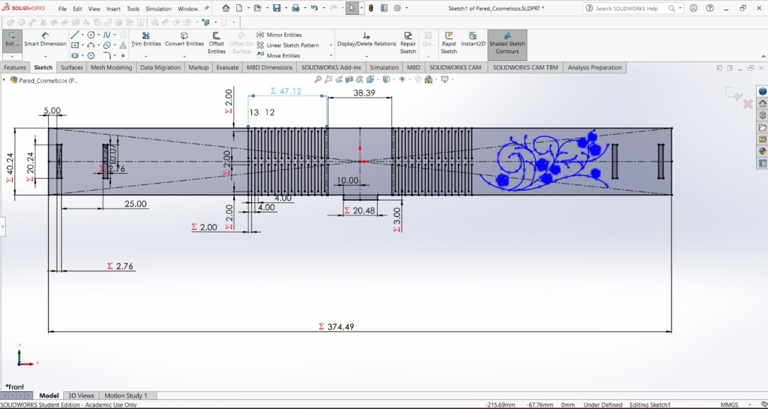
For making a parametrc design in SOLIDWORKS we need to create a new part, then go to the top menu and click the Tool section and select ∑ Equations.
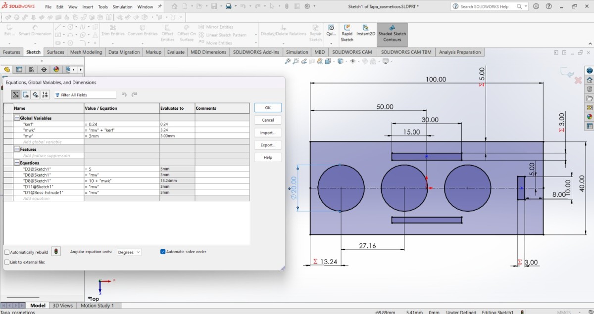
Equations menu
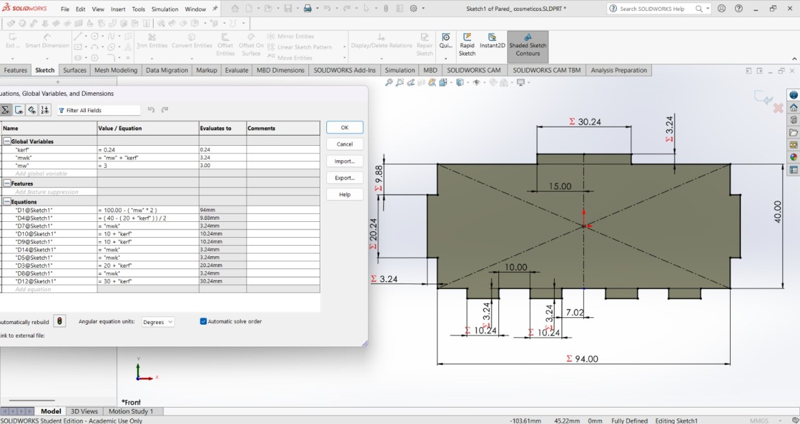
The Equations menu enables dimension linking and global variables, allowing fast design iterations, scalability, and precise change control.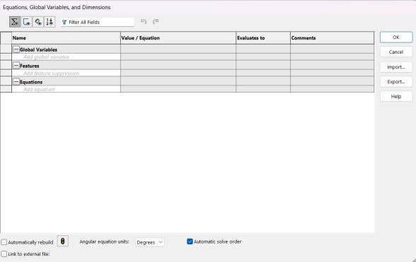
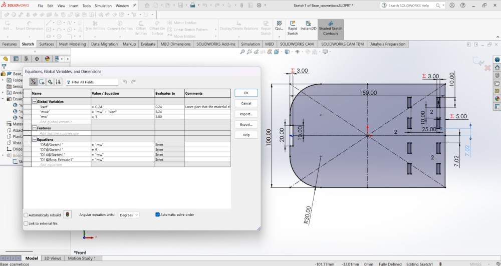
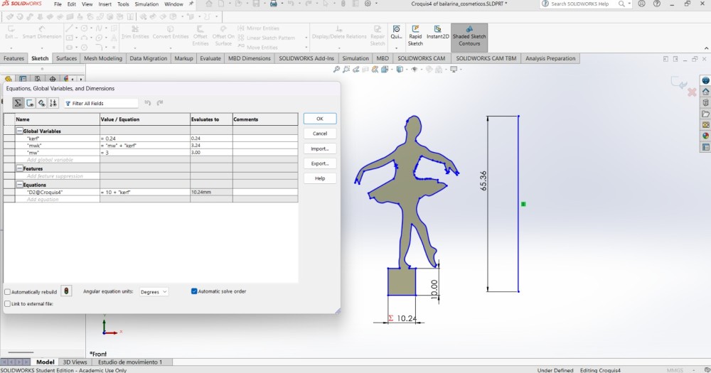
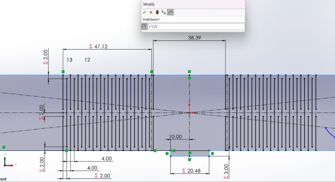
Global Variables
Global variables are concepts that store numerical values and can be referenced by multiple dimensions and features of the model.
They can be defined in the Equation Manager or directly when assigning a dimension, by typing "=" followed by a .
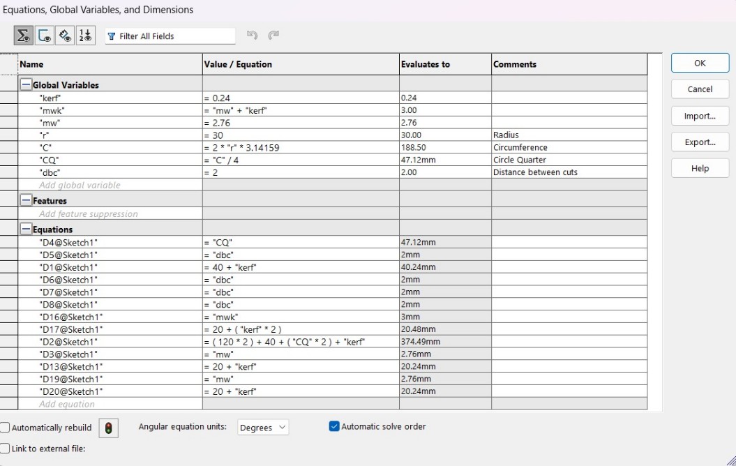
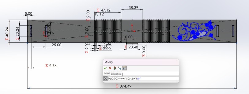
Value/Equations
The Value/ Equations section is where the numerical values and variables operations are assigned.
Evaluates to
In this section is displayed the value that the program will interpretate.
Comments
This space is to place additional information of the Global variable.
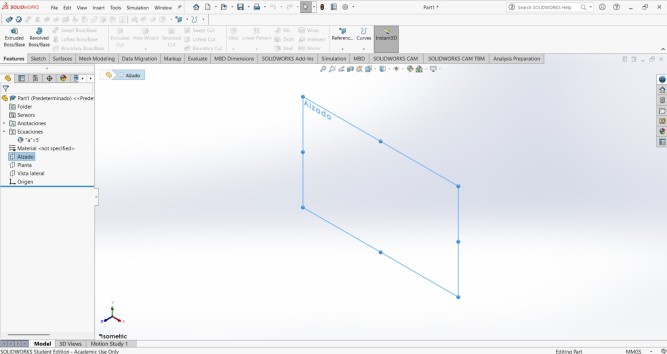
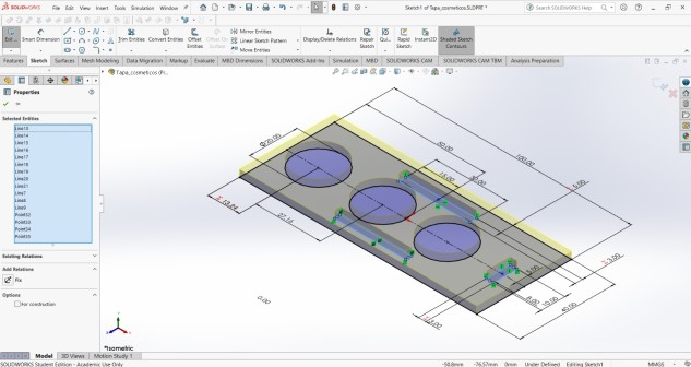
Exporting
To cut our pieces we need to export them as DXF files. We have two easy ways.
1. The first one is to go to the top, and click File and Save as, then save each piece as a DXF file and open them in the laser cut program.
2.The other way is to open a new Drawing and paste each piece in it.
I used the first way and I'll show later how to cut those pieces.
Laser Cutting
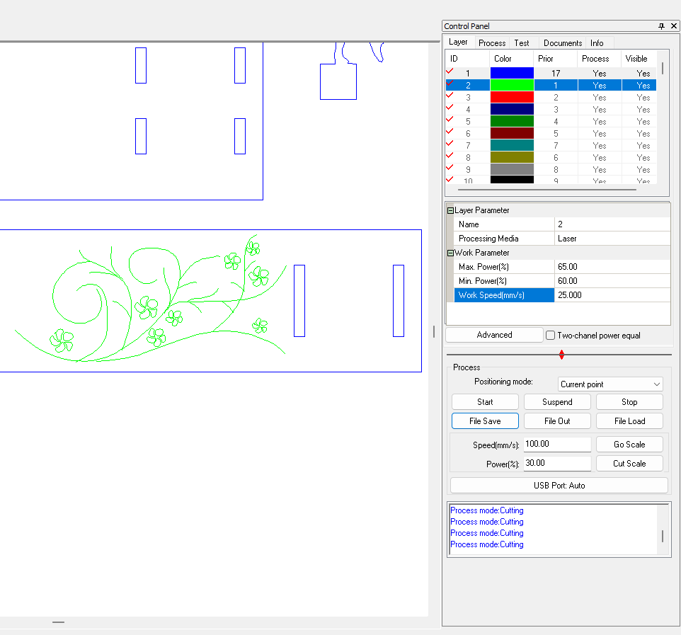
To cut our pieces I used Smart Carve. Smart Carve is a software and hardware license system that uses an usb key, designed for controlling laser cutting and engraving machines.
Smart Carve
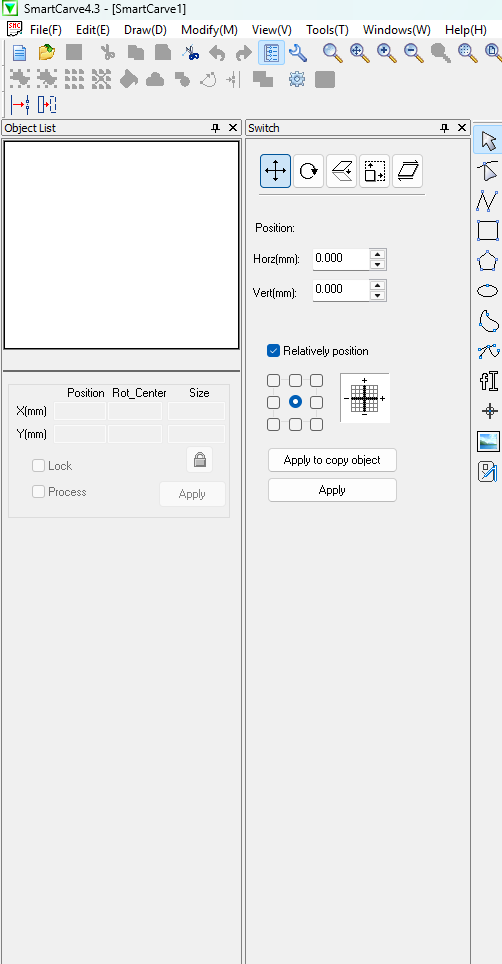
First, we need to have the program and the key. Once we have them we need to import our DXF files by clicking File in the top menu and selecting Import File.
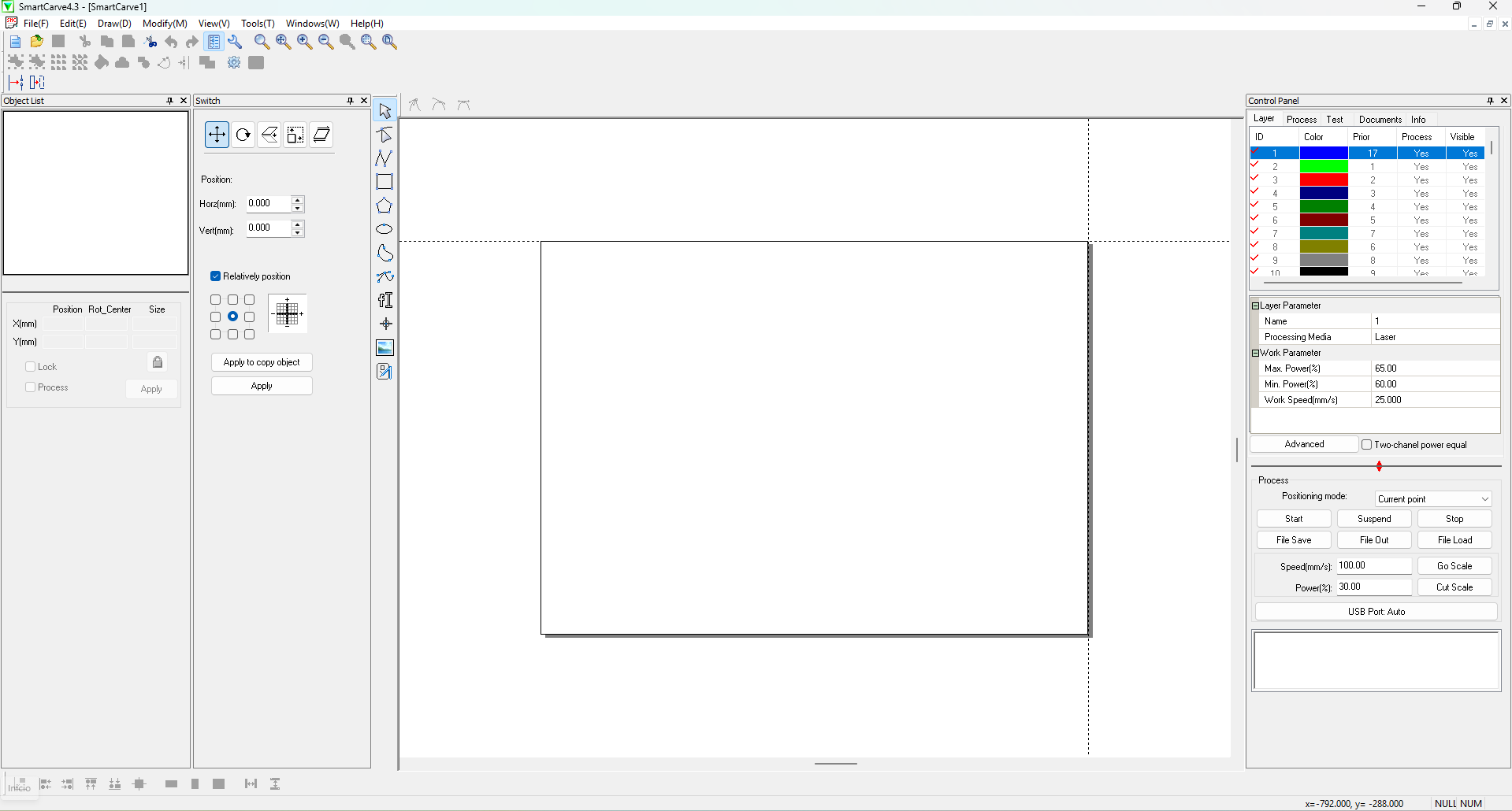
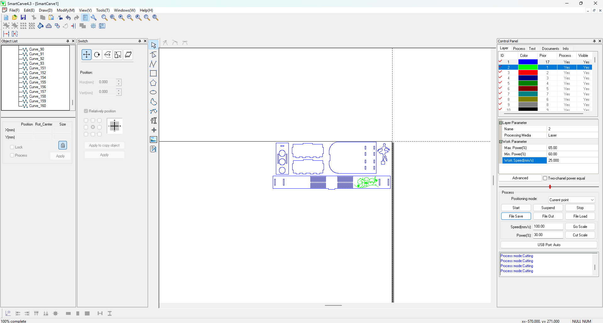
Having imported our files, in the left side we can choose between moving them around the workspace, edit the nodes, or even rotate them. In the right side we can apply different layers with different cut parameters and at the bottom we can export our cutting (.oud) document by clicking File Save.
The cutting parameters of the layers involve: Max. Power(%), Min. Power(%) and Work Speed(mm/s).
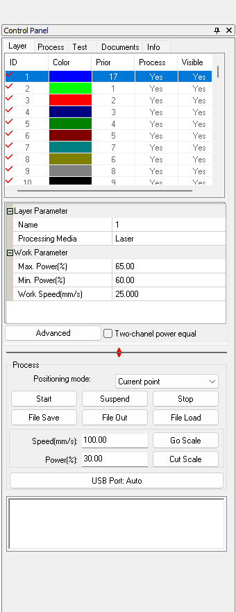
My parameters
Cut Max. Power(%): 65, Min. Power(%): 60 and Work Speed (mm/s): 20.
Engrave Max. Power(%): 25, Min. Power(%): 20 and Work Speed (mm/s): 200.
Steps for turning on the machine
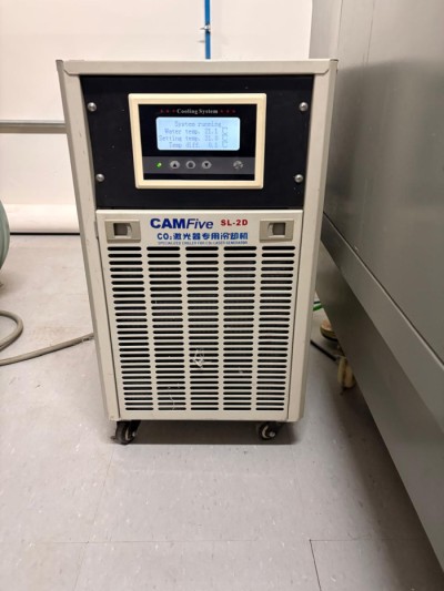
1.Check if the chiller is on, because it keeps a safe temperature inside the machine.
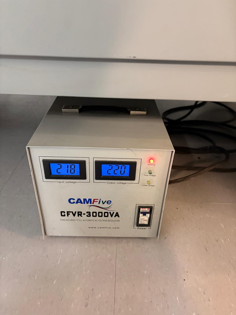
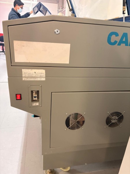
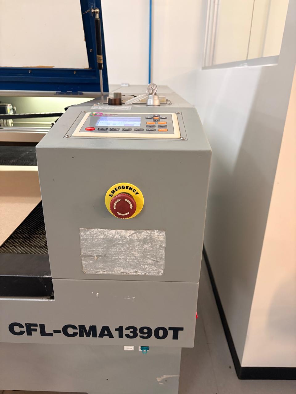
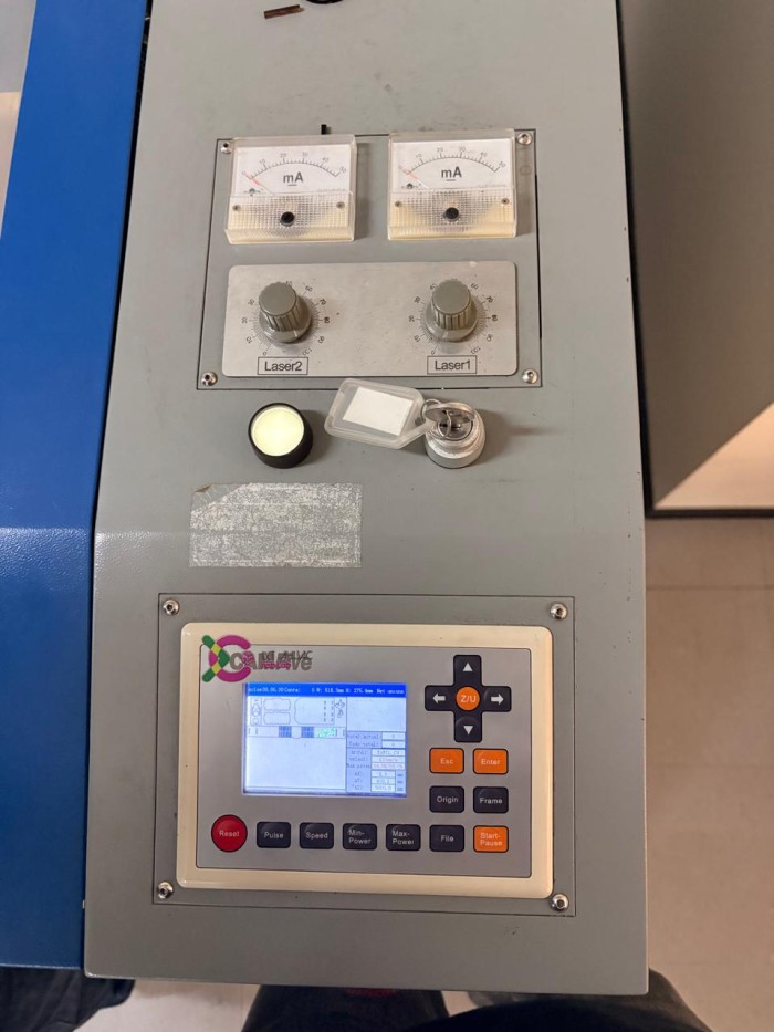
2.Turn on the machine. For that we have to turn on the automatic voltage regulator, press the right side buttons and release the emergency stop. We also need the security key to turn on the machine.
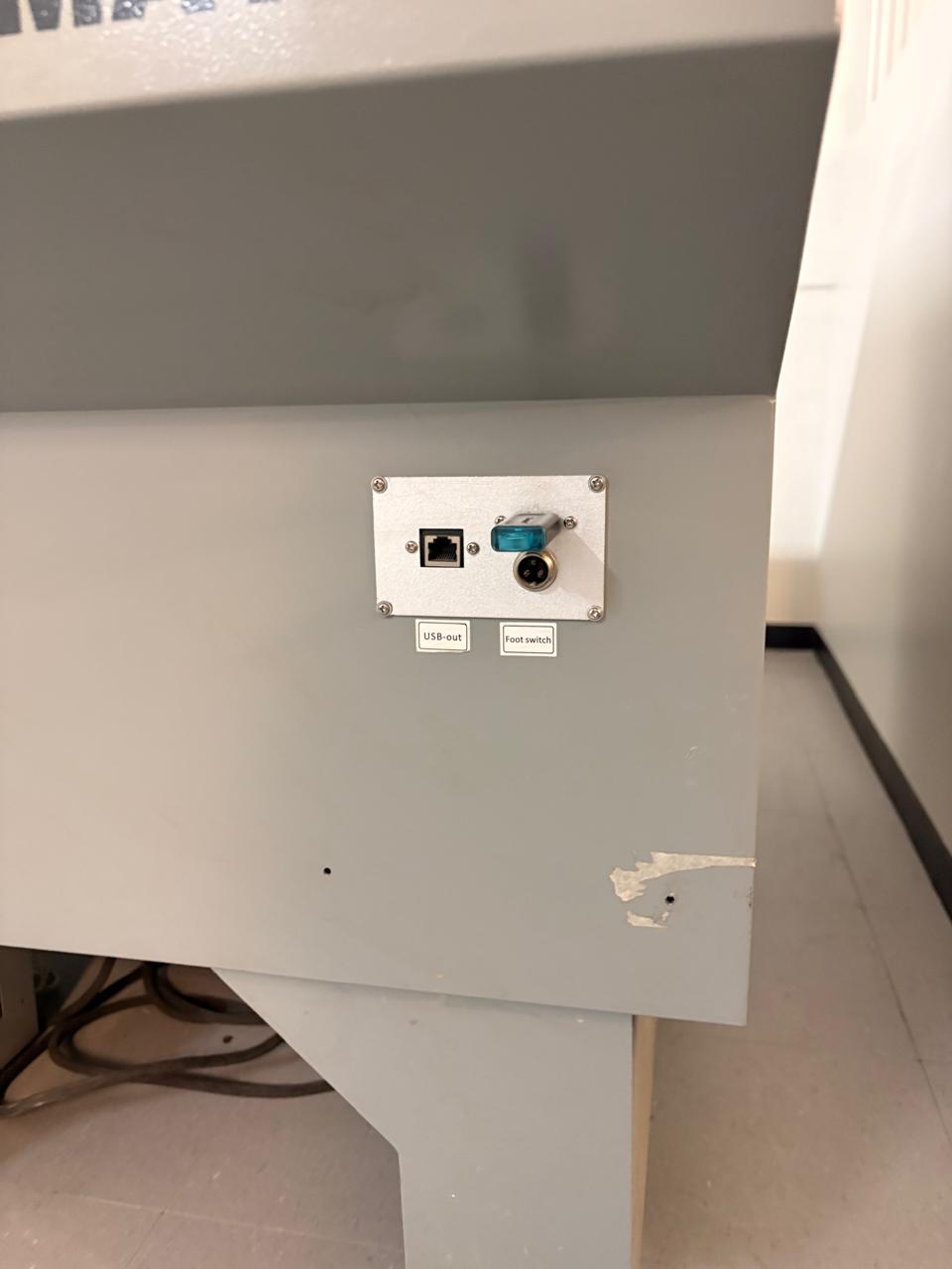
3.Then we have to add our file to the machine. We have to insert a USB memory with our .oud file.
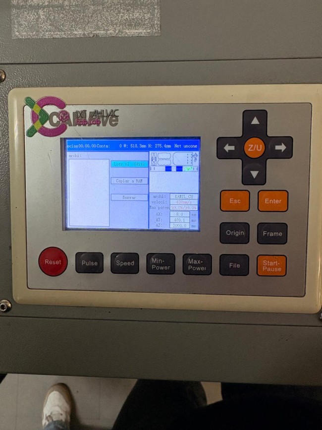
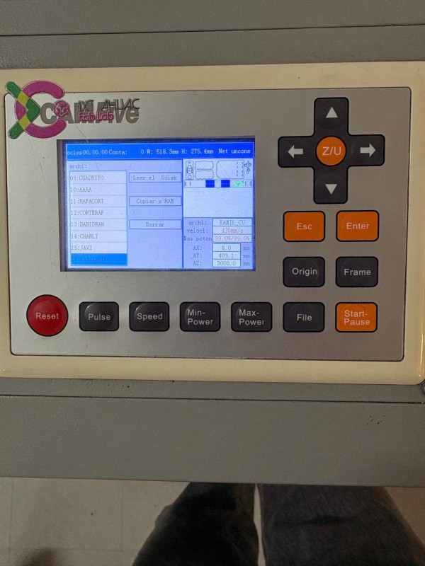
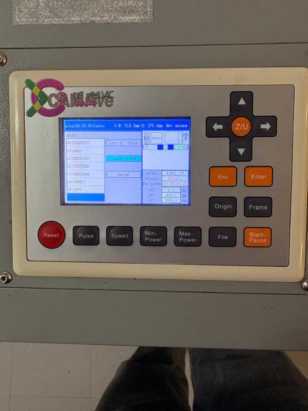
4. To add our file, we first have to read our USB disk, by clicking file, then the right control button and enter. Then look for our file and copy it to the RAM.
Subsequently, we only have to be ready tu cut.
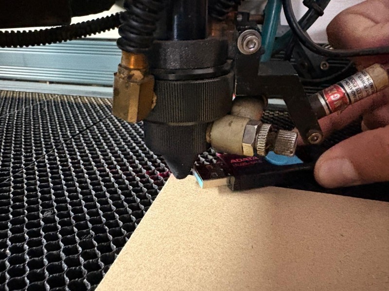
5. Before cutting it is important to adjust the distance between the laser and the material. The recomended distance for this machine is 5 mm, so we can adjust it with a USB.
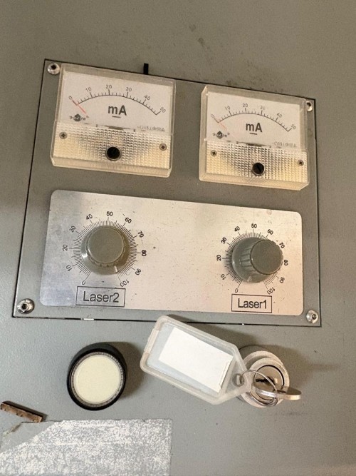
6. To cut we have to turn the knob from 0% to 100% and press the white button. It is important to never put your hand inside the machine while it is on, because you can get seriously damaged.
Safety reflection
During this process I learned a lot about the safety of the cutting process. First and foremost we never, never have to put our hand inside the machine while working, we cand get severe burns. We also shouldn't be looking at the laser for a long time because we can damage our eyes. It is recomended to close the machine cover while working in order to not inhale the smoke it produces. If the machine is producing fire while cutting we must turn it off inmediately to not provoque a fire.
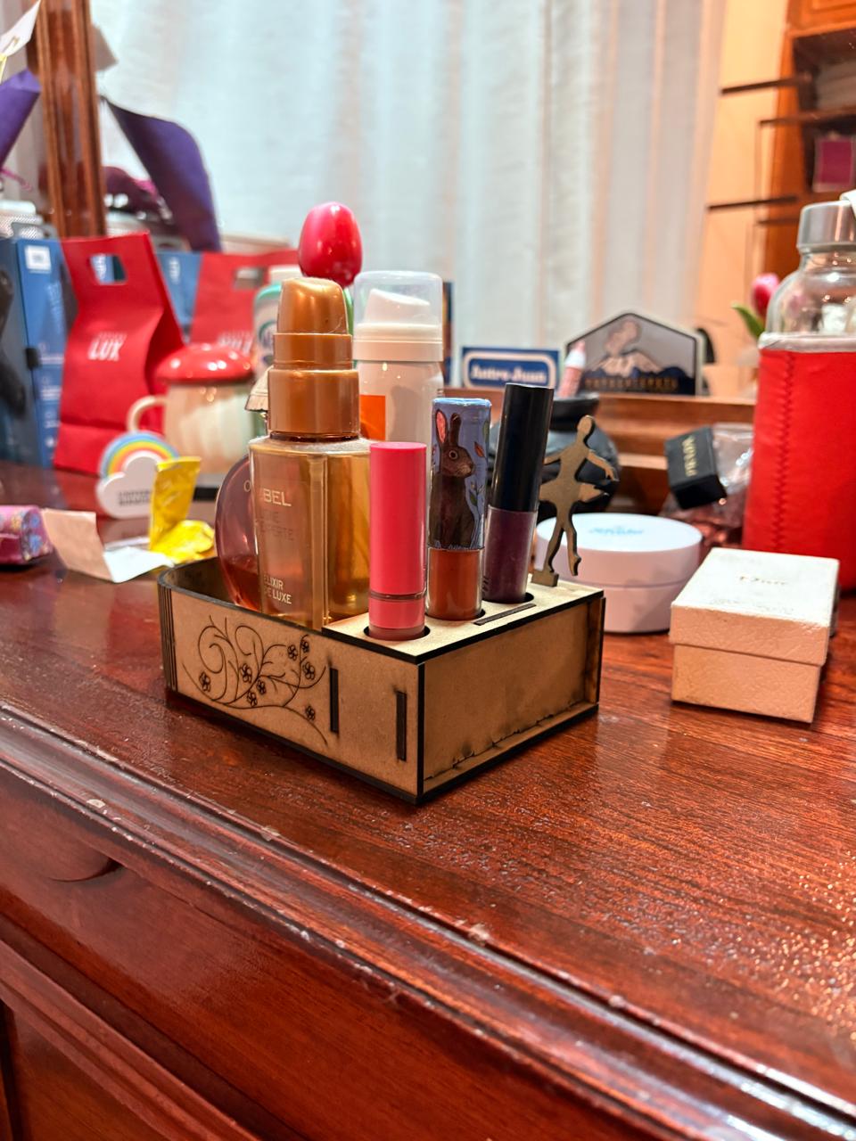
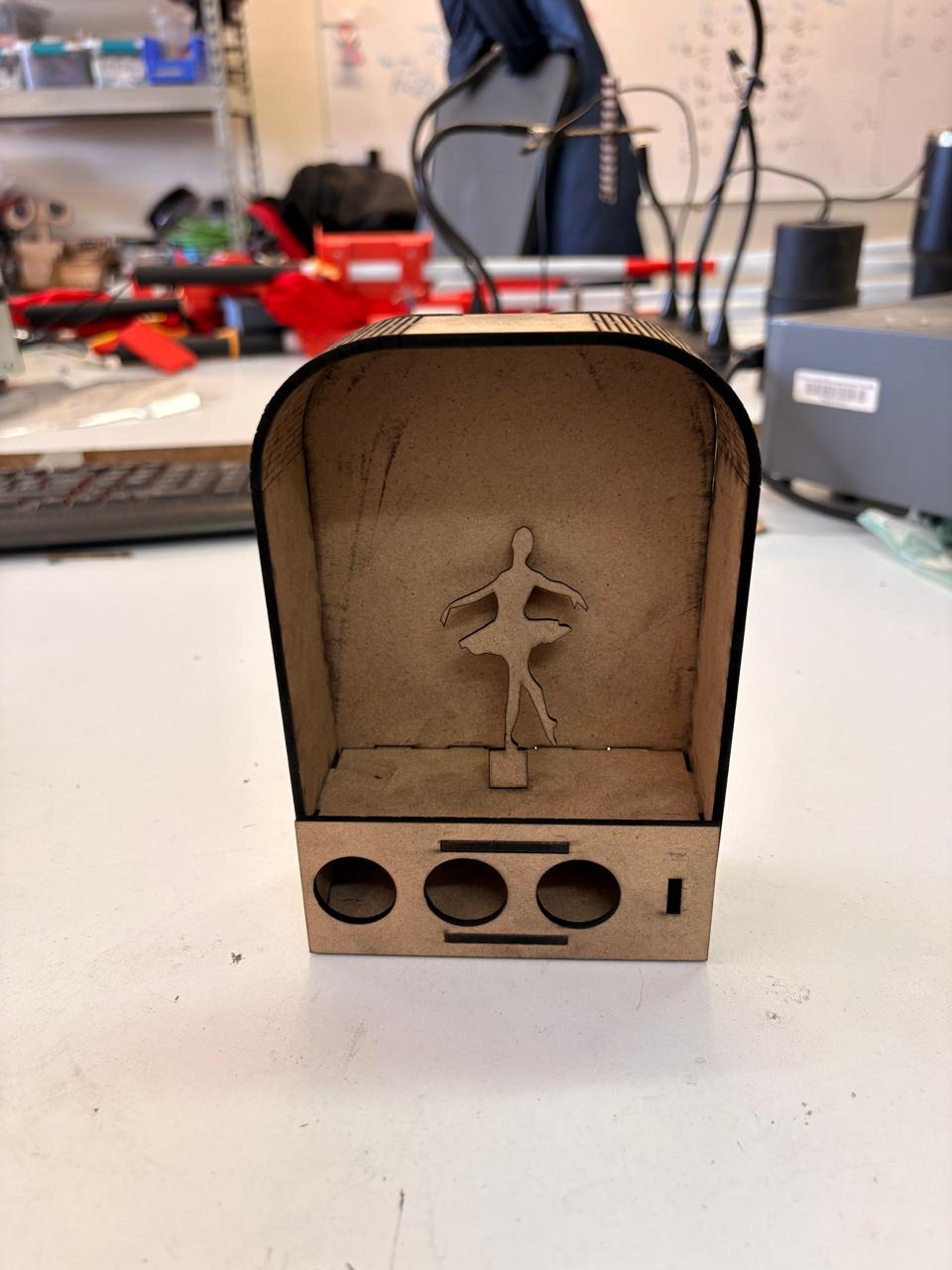
Laser Results
Laser

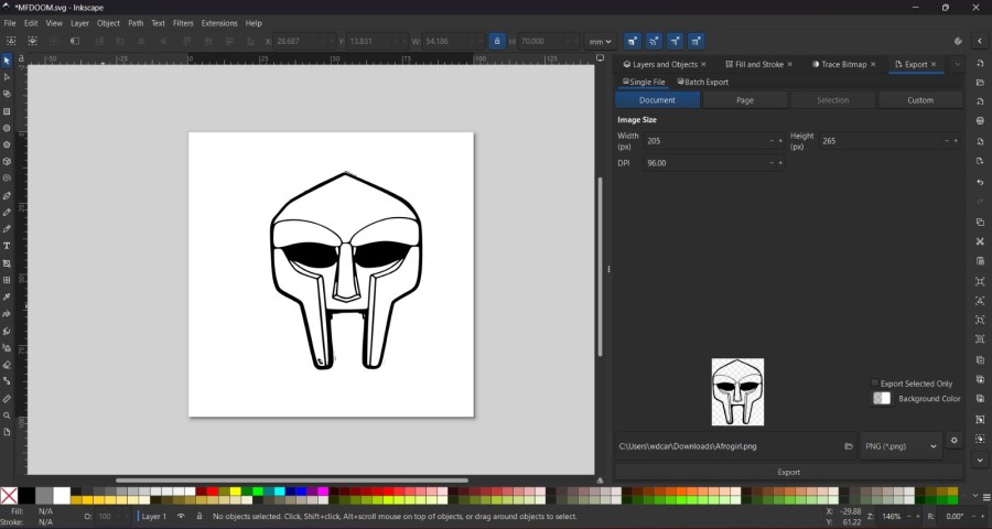
Vinyl Cutting
For the Vinyl cut I used a web PNG image of MF DOOM and vectorized it in Inkscape like I explained in my Week 02 page in the Inkscape section.
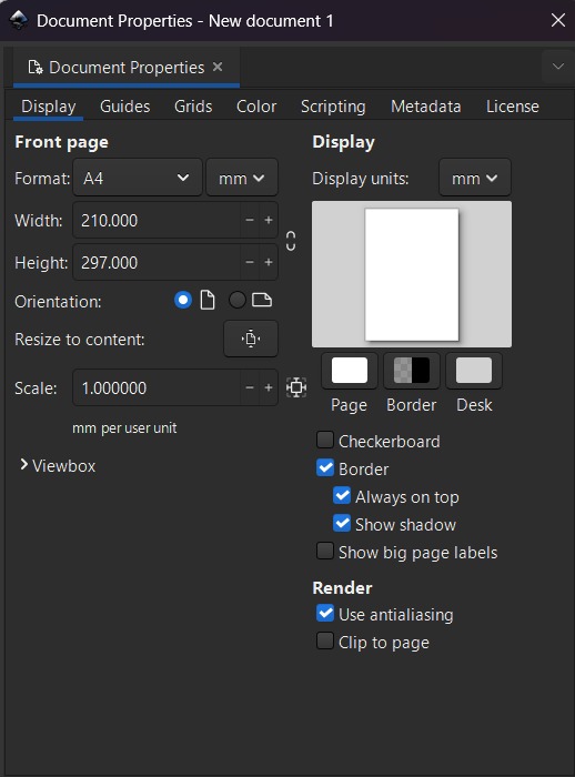
Vinyl Cutting Steps
Using CTRL + Shift + D I adapted the workspace the measure of the vinyl I wanted to cut. We can also use CTRL + Shift + P to measure.
Vinyl Cutting Steps
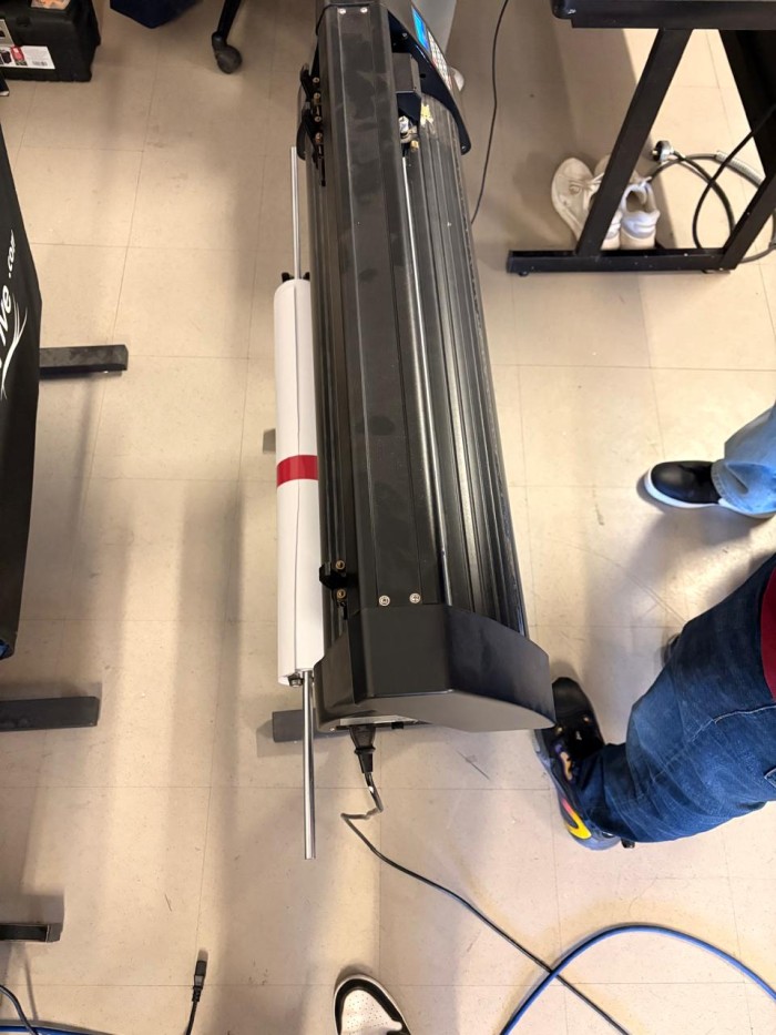
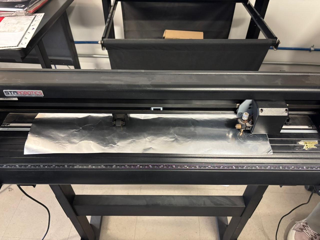
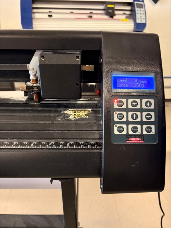
1. Turn on the machine. To turn on the STM ROBOTICS Vinyl Cutter, conect it to power and it will automatically turn on.
2. Insert the Vinyl in the machine. To insert it, we have to put it in from the front and secure it with the two back clips. It is important to make sure that the Vinyl is completely stretched out, If it is wrinkled, the material may shift and the cut will likely not be clean.
Vinyl Cutting Steps
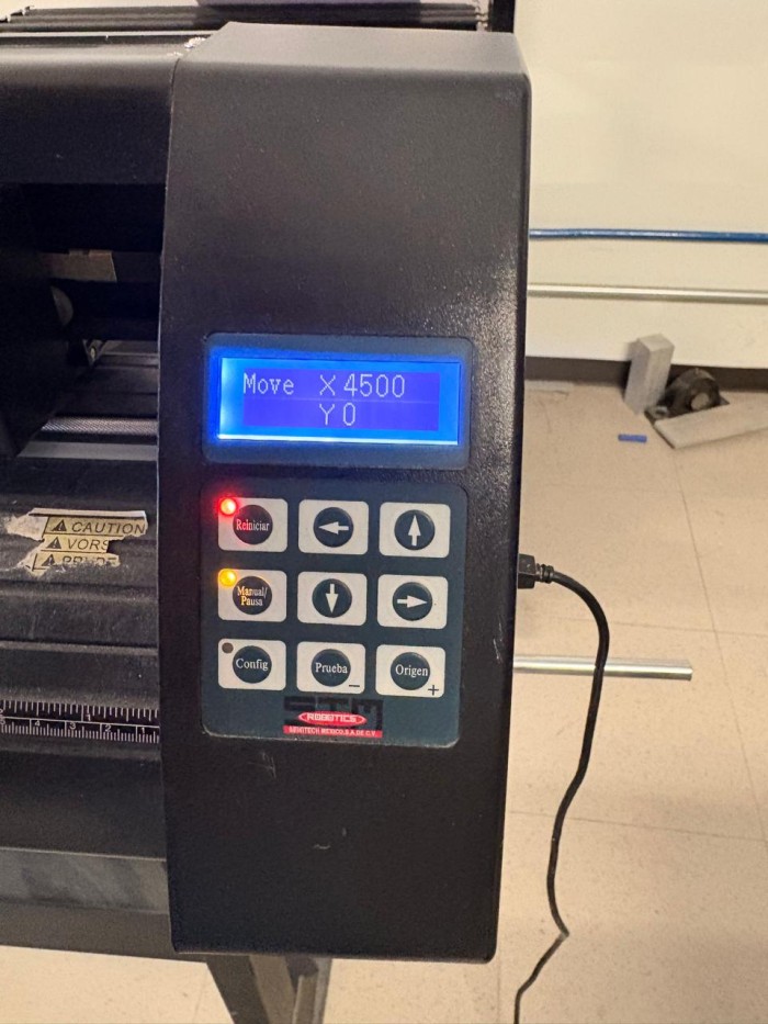
3. Once the vinyl was placed in the machine, the Manual button was selected to activate the setup mode. This made it possible to establish the origin point. With the arrow controls, the cutting head was moved to the desired position, and the origin button was pressed twice to confirm the starting location.
4. Establish the cutting speed and preassure. To modify the cutting speed and pressure, the reset button was selected, and the settings were adjusted using the arrow keys.
Vinyl Cutting Steps
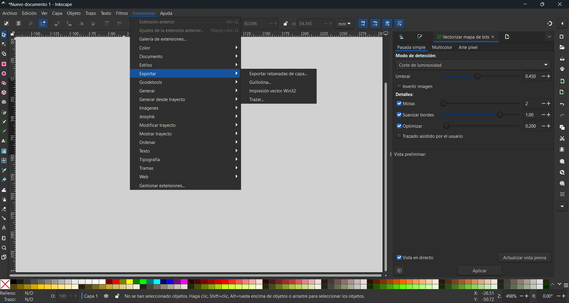
5. Finally, the MF DOOM file was sent to the vinyl cutter using Inkscape. To export, click on Extensions, select Export, and then Trace.
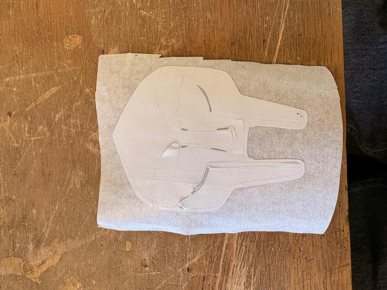
Making it a sticker

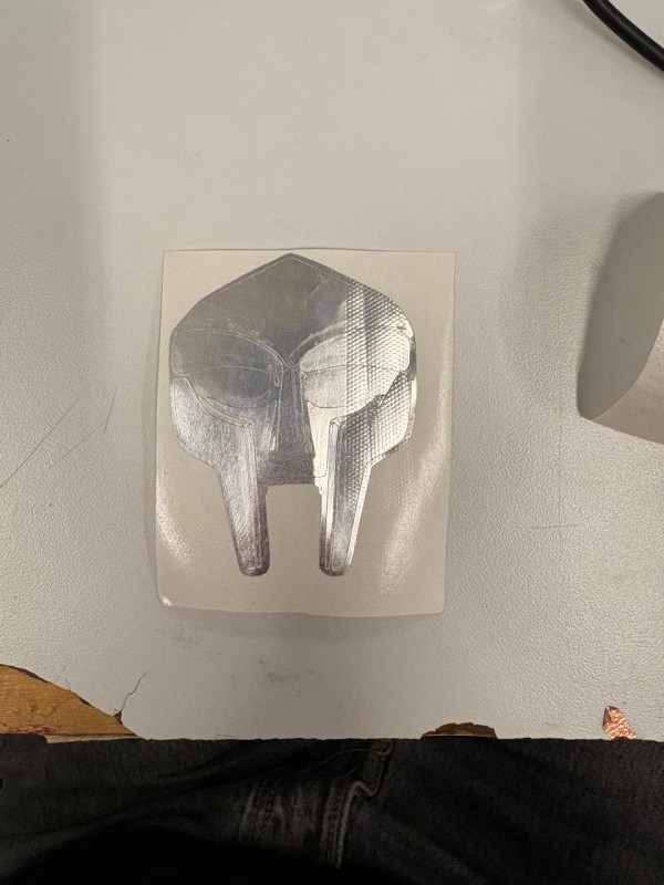
1. First we need to remove the extra vinyl of our piece.
Transfer paper
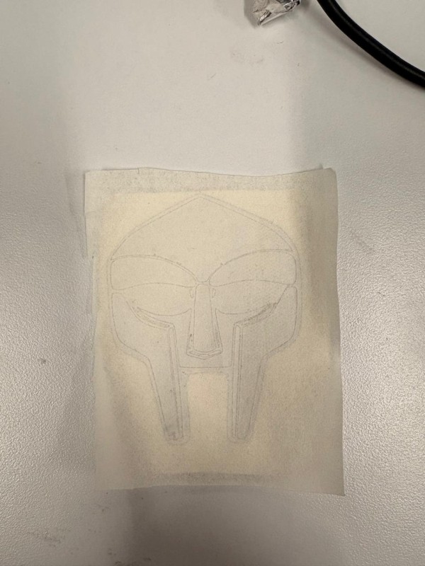
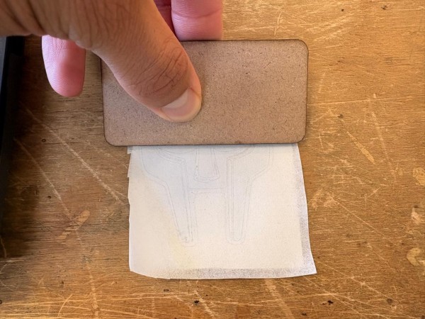
2.Then we have to paste over our sticker face transfer paper in order to be able to remove the backing paper of our piece.
Pasting it
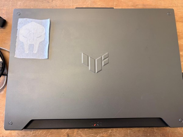
3. Finally, we have to remove the backing paper and paste it on the desired surface.
Vinyl Cutting Steps
5. Finally, the MF DOOM file was sent to the vinyl cutter using Inkscape. To export, click on Extensions, select Export, and then Trace.
My parameters
Cut Speed (mm/s): 60, Force (g): 330.
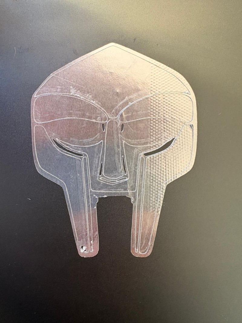
Vinyl Results
Vinyl
Learning outcomes
This week, we created a parametric design, laser cut it, and also produced a vinyl cut. Before this experience, I was not particularly interested in parametric design because I did not consider it necessary. However, I now realize that it is extremely useful and practical, since it allows small parameter changes to produce significant modifications in a design without starting from scratch.
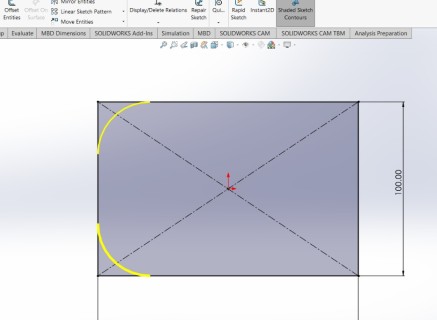
I had previous experience with laser cutting, but I had never designed a piece that required circumference calculations to achieve rounded and flexible edges. Working with a living hinge was especially enjoyable, as it demonstrates how a material can be both rigid and flexible at the same time. Designing something that combines structural strength with flexibility is very satisfying.
Vinyl cutting is also a highly versatile process that enables the creation of many useful applications, such as flexible PCBs, stickers, and labeling elements. For this reason, it is a technology that should not be underestimated.
I am still considering using laser-cut components for parts of my final project; however, I have some concerns about their impact resistance and mechanical durability.