Week 2: Computer aided design
CAD
CAD (Computer-Aided Design) involves using specialized software to produce 2D drawings and 3D models. These programs help designers test,
adjust, and improve their projects before production, offering greater accuracy and detail than traditional manual drafting methods.
These tools enable version control, code editing, and synchronization of files throughout the documentation process.
3D Softwares
- SOLIDWORKS
- ONSHAPE
- CATIA
- BLENDER
- FUSION 360
2D Softwares
- INKSCAPE
- AFFINITY
- ADOBE ILLUSTRTATOR
SOLIDWORKS
SOLIDWORKS is a 3D computer-aided design (CAD) software for creating accurate models of parts and assemblies, simulating their performance, generating technical drawings, and managing the entire product development process, from concept to manufacturing.
It is essential in engineering, industrial design, and manufacturing for visualizing, analyzing, and prototyping products before physically producing them.
To use SOLIDWORKS, you must have a user license, which can be purchased or obtained through membership in an educational or professional institution. In my case, my university has SOLIDWORKS user licenses.
HOMEPAGE
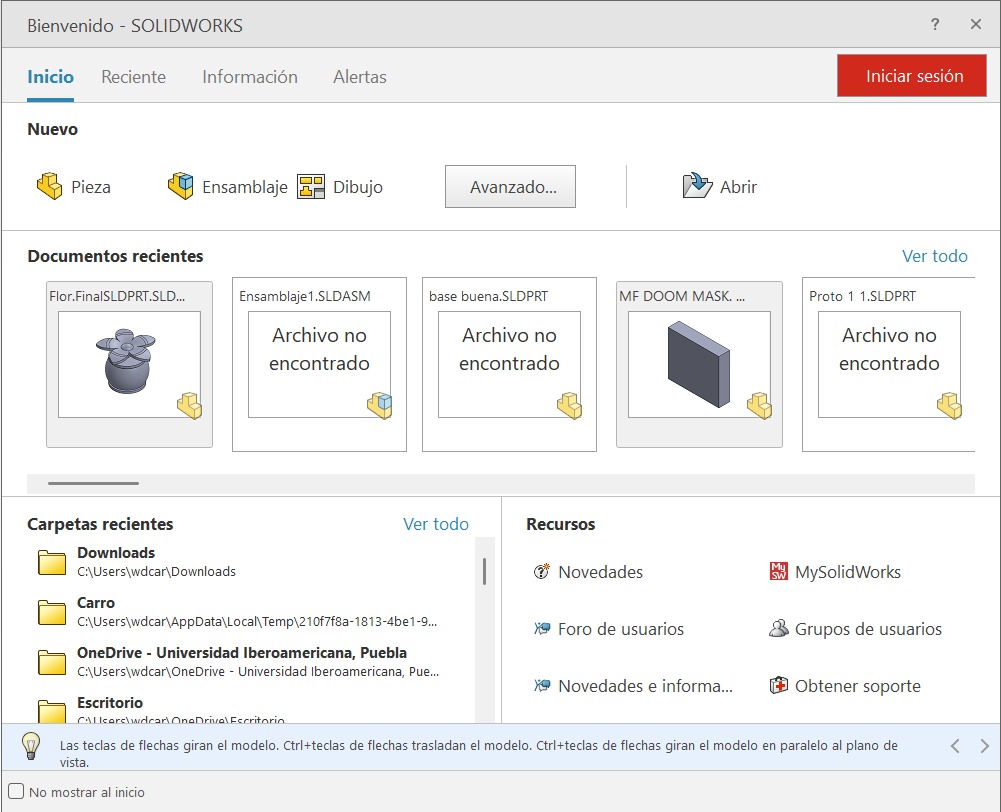
When you open SOLIDWORKS, a tab will automatically appear allowing you to select different options:
Part: To create parts.
Assembly: To assemble existing parts.
Drawing: To make drawings of the parts.
You can also select previously created parts and folders.
PART
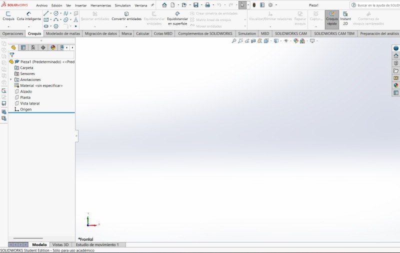
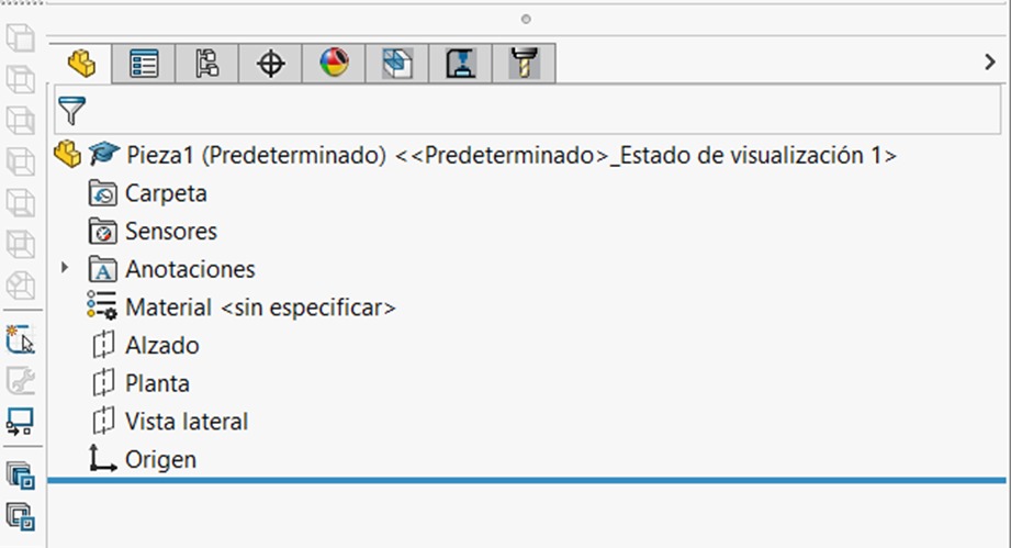
TOOLS

At the top, you can see the different tools that the program offers. In my opinion, the most relevant ones are:
Feature
The toolbar section for 3D parts, including tools for extrude, revolve, loft, sweep, fillet, and shell.
Sketch
The toolbar section is for Sketching a part.
Surfaces
Provides specialized tools for creating, editing and manipulating zero-thickness surface bodies, essential for complex, organic, or aerodynamic shapes.
Mesh Modeling
Provides specialized tools for editing and manipulating STL, OBJ, and 3MF mesh data directly.
Data Migration
Contains tools to help you migrate solid or surface data.
Evaluate
Provides essential tools for analyzing, measuring, and validating parts and assemblies, including Measure, Mass Properties, Interference Detection, and Performance Evaluation.
SOLIDWORKS Add-ins
Specialized, integrated modules that enhance the core CAD software with advanced, industry-specific capabilities like simulation, data management ,and rendering
Rendering Tools
These tools enable users to apply, edit, and manage appearances, scenes, lighting, and cameras to enhance product visualizations.
Simulation
Provides a virtual testing environment for static linear motion, it can be used to understand how a part or product will perform.
SOLIDWORKS CAM
Integrated, rules-based manufacturing software that enables 2.5-axis milling, turning, and assembly programming directly within the SOLIDWORKS CAD environment.
SOLIDWORKS CAM TBD
It utilizes 3D design data to automatically determine machining strategies based on tolerance specifications.
Analisys Preparation
Available in part files, it detects and suppresses unnecessary features (fillets, chamfers, holes) to reduce simulation complexity.
It is important to note that more tools can be added to the toolbar by right-clicking one of the existing tabs, and selecting Customize.
FEATURES

Extruded Boss/Base: Extrudes a sketch in one or two directions to create a solid feature.
Revolved Boss/Base: Revolves a sketch around an axis to create a solid feature.
Swept Boss/Base: Sweeps a closed profile along an open or closed profile to create a solid feature.
Lofted Boss/Base: Adds material between two or more profiles to create a solid feature.
Boundary Boss/Base: Adds material in two directions between profiles to create a solid feature.
Extruded Cut: Cuts a solid model by extruding a sketch in one or two directions.
Hole Wizard: Inserts customized holes of various types.
Revolved Cut: Cuts a solid model by revolving a sketch around an axis.
Swept Cut: Cuts material by sweeping a closed profile along a closed or open path.
Lofted Cut: Cuts a solid model by removing material between two or more profiles.
Boundary Cut: Cuts a solid model in two directions, by removing material between two or more profiles.
Fillet: Creates a rounded internal or external face along one or more edges on a solid or surface feature.
Chamfer: Creates an angled edge connecting two surfaces, typically cut at a 45-degree angle to replace a sharp, 90-degree corner.
Pattern: Pattern features faces and bodies in one or two directions, it can be linear, circular, curve, etc.
Rib: Adds thin-walled support to a solid body by adding material between one or more sketch contours and an existing part.
Shell: Leaves open the face you select and add thin-walled features on the remaining faces.
Mirror: Mirrors features, faces and bodies about a plane.
Reference geometry: Display reference geometry commands, like planes, axis, coordinate systems or points.
SKETCH

Sketch: Creates a new sketch or edit and existing sketch.
Smart Dimension: Creates a dimension for one or more selected 2D or 3D sketch entities.
Line: Sketches a line, centerline or midpoint line.
Rectangle: Sketches a center rectangle, corner rectangle, Parallelogram, etc.
Slot: Sketches a Straight Slot, Center Point Straight Slot or a 3-point arc slot.
Circle: Sketches a Circle.
Arc: Sketches a 3-point arc, Tangent arc or a Centerpoint arc.
Polygon: Sketches a polygon.
Spline: Sketches a Spline.
Ellipse: Sketches a complete ellipse. It can also sketch a Parabola.
Sketch fillet: Round the corner where two sketch entities intersect to create a tangent arc.
Plane: Inserts a plane into the 3D sketch.
Text: Inserts text.
Point: Inserts a point.
Trim Entities: Deletes a sketch entity.
Mirror Entities: Mirrors entities about a centerline or planar surface.
Sketch Pattern: Adds patterns of sketch entities.
Move Entities: Move sketch entities and annotations.
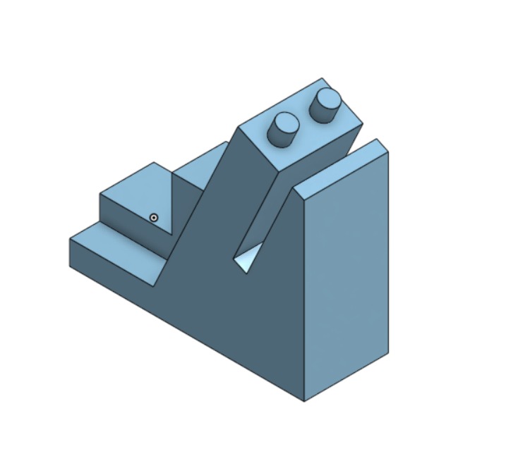
PIECE
SOLIDWORKS offers infinity ways to make a piece. This is an example.
Steps for making a piece
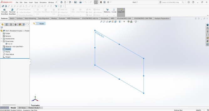
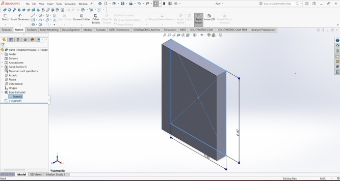
1. First I created a sketch in the front plane.
Steps for making a piece
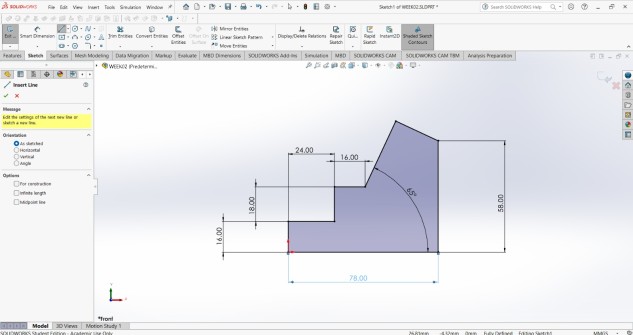
2. Then I traced a line with the line.
Steps for making a piece
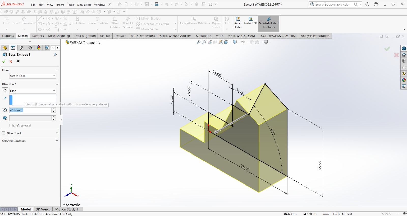
3. After that, I extruded the piece with the extrude tab in the toolbar.
Steps for making a piece
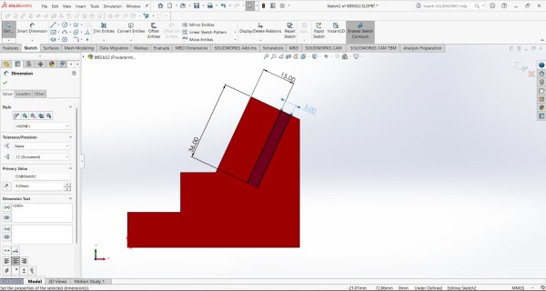
4. I made sketch on the left face of the piece and proceded to extrude a cut through all.
Steps for making a piece
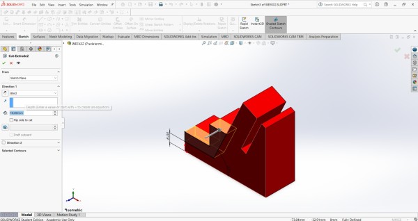
4. I made another sketch on the left face of the piece and proceded to extrude a cut through an especific meassure of 10 mm.
Steps for making a piece
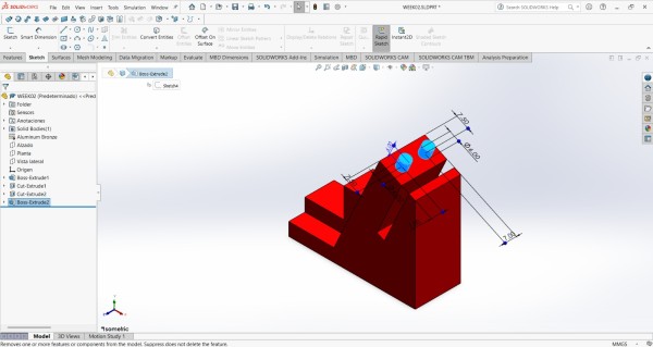
5. Finally, I created a Sketch a in the top of my figure and extruded two circles.
Result

RENDER
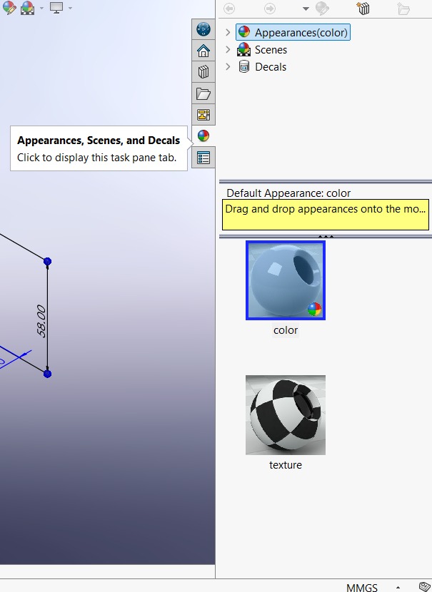
Before rendering we should add an appearance and a scene.
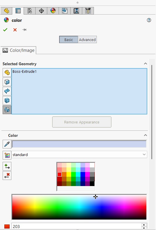
To add an appearance, click on the appearance symbol (four-section colored circle) located below the toolbar or in the right side toolbar, and a menu will appear. In that menu, you can change the color of the piece, add a scene, texture, and much more.
After opening the menu, in the left side, our piece will be already selected, so we can go to the bottom and choose the color of our preference.
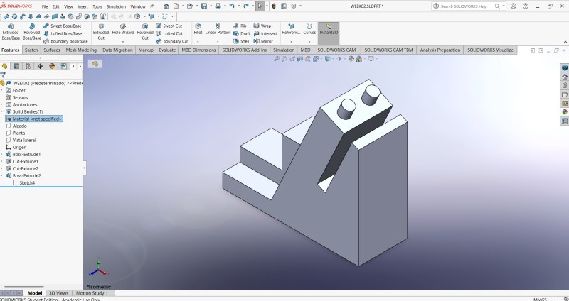
You can also try adding a material to your piece to reflect light. For that, it is necesary to go to the FeatureManager Design Tree and look for Material.
For rendering, we need to have our piece finished, I'm going to use the one that I made earlier.
Then we have to go to the SOLIDWORK Visualize section and export the piece by selecting Export Simple.

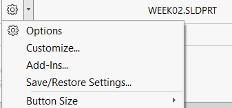
If you don't have this feature, in the top is the Options symbol, after clicking it a tab will be displayed and make sure to click on Add-Ins.And then we just add SOLIDWORKS visualize.
Shortly after exporting the piece, another window will open. This window is the SOLIDWORKS visualize workspace.
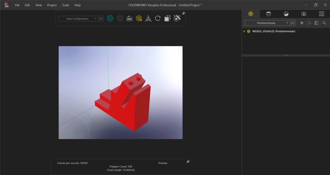
SOLIDWORKS visualize allows you to edit the scene, camera, brightness, contrast, rotate your figure, change both the camera perspective and the position of the figure, among many other things. It is a very complete rendering tool that I highly recommend using.
Some useful tools

Render selection: Let you select the realtime rendering.
Turntable: Rotates your piece in real time.
Selection tool: It allows you to select your figure. If you have a an assembly, select a single-piece or the whole set, and edit its appearance.
View preset: Display the scene from a preset position.
Render Wizard: Adds material between two or more profiles to create a solid feature.
Scenes: Allows you edit the background.
Camera: Allows you to personalize the perspective, the lenght of the lense and a lot more things of the point of view of the piece.
To export your render, click on the Render Wizard. There you can select the type of document you want to export, the quality, the format, and where you want to save it.
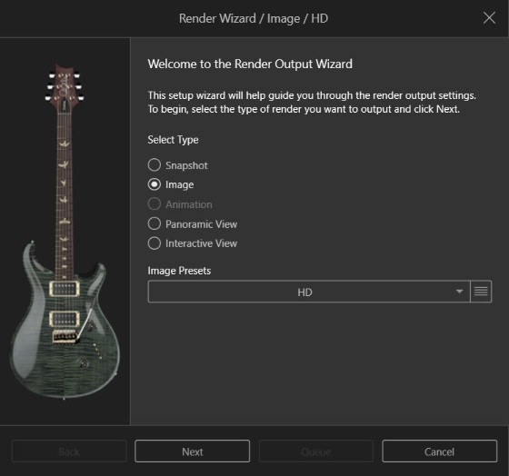
After clicking Next, here we can choose the type of document we want to save.
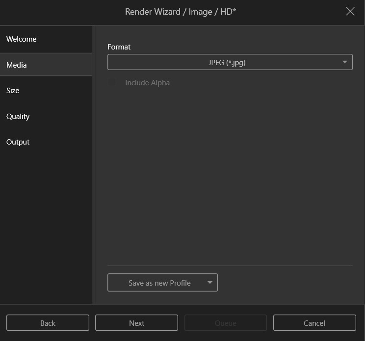
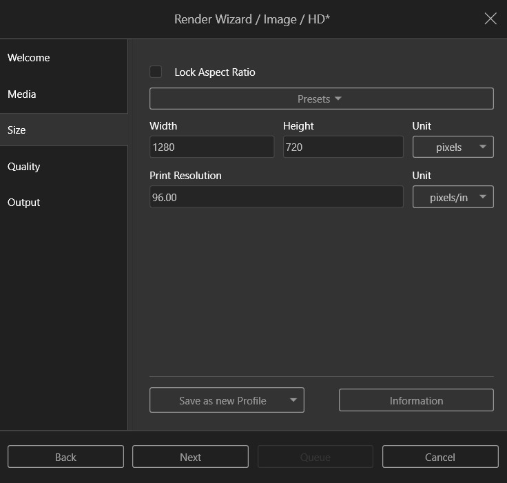
After clicking Next, here we can choose the dimensions of our render document.
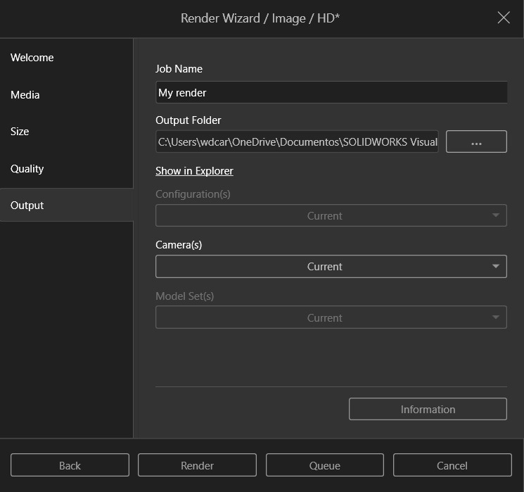
After clicking Next, here we can choose the name and where will we save our render. Finally we can just click render and our render will be saved in our computer.
My render
1. To make my render I did the previous steps, and my piece was opened in the workspace.
2. Then I went to the camera tool and changed a little bit the perspective and the Focal lenght.
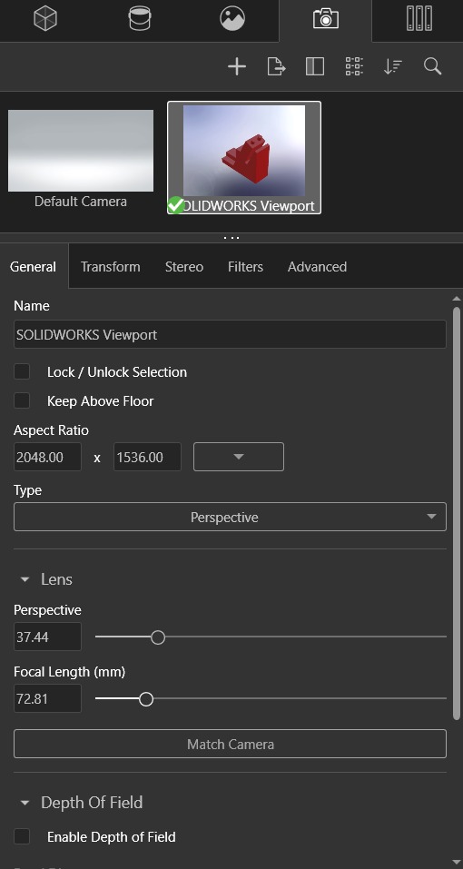
2. Finally, I just exported my render.
Result
Onshape
Onshape is a cloud-native, SaaS (Software as a Service) 3D computer-aided design (CAD) and product data management (PDM) platform, developed by PTC. It runs directly in web browsers and mobile devices, allowing engineers to design, collaborate in real-time, and manage data without installing software or managing files.
As with SOLIDWORKS, you need to purchase a license to use Onshape. However, Onshape is more affordable, and if you are using it for educational purposes, you can purchase it free of charge for the duration of your studies.
To use Onshape, you must create an account. Once you have created your account, the following menu will appear:
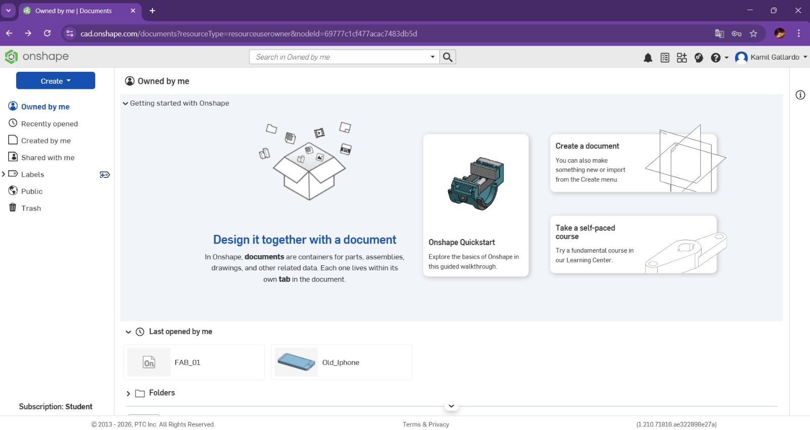
Where we can create or assemble new parts, the menu also displays previously created parts, as well as shared parts. In our case, we will create the same part modeled in SOLIDWORKS, therefore we will click Create and select Document.
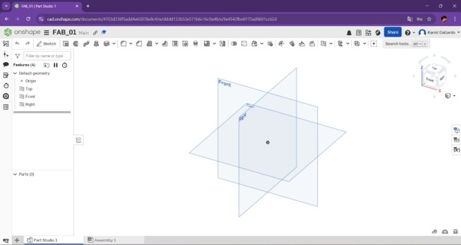
When creating the new part, another tab will open with the workspace. By default, the three views (Top, Front, and Right) can be displayed in the workspace.
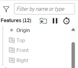
In the Features section, you can view the basic geometry (planes and origin point), as well as our part and the history of changes we have made to it.

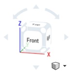
To the left of the Features, there is a bar with more utilities, such as Comments, Document Notes, Performance, even an AI advisor, but the most important of them is Versions and history, because that is where we can see the list of changes made to our document. At the top left of the work area, there is a cube that allows us to position the view as we move it. It is extremely useful for seeing other perspectives of the part.
At the bottom of the document, you can see two tabs: Part Studio 1 and Assembly. Part Studio 1 is the newly created part, while Assembly is the space where you can assemble that part with others.
Toolbar
Sketch: Creates a new sketch or edit and existing sketch.
Extrude: Extrudes a sketch in one or two directions to create a solid feature.
Revolve: Revolves a sketch around an axis to create a solid feature.
Sweep: Sweeps a closed profile along an open or closed profile to create a solid feature.
Loft: Adds material between two or more profiles to create a solid feature.
Thicken: Create, add to, subtract from or intersect part by thickening surfaces.
Enclosure: Create, add to, subtract from or intersect part by selecting faces, surfaces and parts that enclose a region.
Fillet: Creates a rounded internal or external face along one or more edges on a solid or surface feature.
Chamfer: Creates an angled edge connecting two surfaces, typically cut at a 45-degree angle to replace a sharp, 90-degree corner.
Draft: Add a draft angle to one or more face by selecting a neutral plane.
Rib: Adds thin-walled support to a solid body by adding material between one or more sketch contours and an existing part.
Hole: Inserts customized holes of various types.
Shell: Leaves open the face you select and add thin-walled features on the remaining faces.
External thread: Add an external thread to a cylindrical part by selecting a leading edge or edges.
Pattern: Pattern features faces and bodies in one or two directions, it can be linear, circular, curve, etc.
Mirror: Mirrors faces and bodies about a plane.
Boolean: Perform a union, subtraction or intersection on two or more surfaces or parts.
Split: Select entities to split.
Transform: Transform or wrap a face around a part. It can also add images to faces.
Plane: Creates a new plane by referencing the existent geometry. This tool has a lot more features inside, like variables, Helix, Fill, etc.
Add custom features: Adds more features and customize the existent ones.
Sketchbar
Extrude: Extrudes a sketch in one or two directions to create a solid feature.
Revolve:Revolves a sketch around an axis to create a solid feature.
Line: Sketches a line, centerline or midpoint line.
Rectangle:Sketches a center rectangle, corner rectangle, Parallelogram, etc.
Circle: Sketches a Circle
Arc: Sketches a 3-point arc, Tangent arc, Centerpoint arc Elliptical arc and a Conic arc.
Polygon: Sketches a polygon.
Spline: Sketches a Spline.
Point: Inserts a point.
Text: Inserts text.
Sketch fillet/ Chamfer:Creates a fillet or a chamfer in the sketch.
Trim Entities: Deletes a sketch entity.
Offset: Creates a copy of the selected sketch and paste it in a specified distance.
Mirror Entities: Mirrors entities about a centerline or planar surface.
Sketch Pattern: Adds patterns of sketch entities.
Insert DXF or DWG
Insert Image
Dimension: adds dimension to a selected entity.
Constrains.
PIECE
Steps for making a piece
1. First I created a sketch in the front plane.
Steps for making a piece
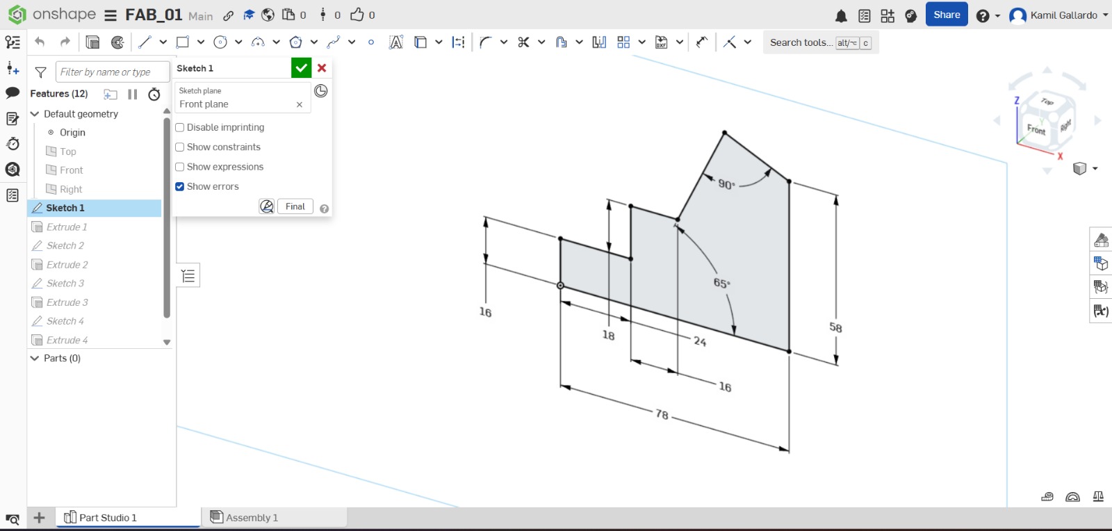
2. Then I traced my figure with the line tool.
Steps for making a piece
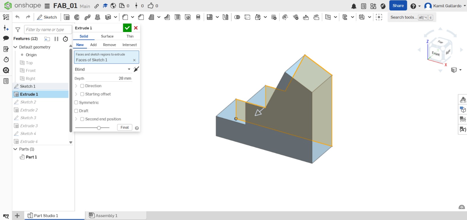
3. After that, I extruded the piece with the extrude tab in the toolbar.
Steps for making a piece
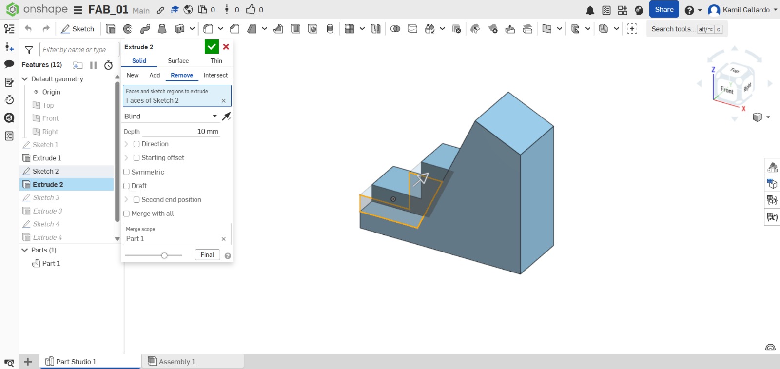
4. I made sketch on the left face of the piece and proceded to extrude a cut through all.
Steps for making a piece
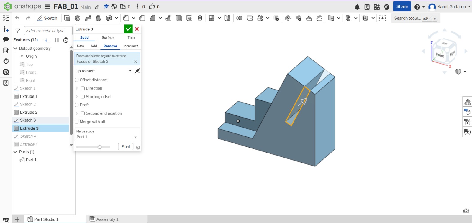
5. I made another sketch on the left face of the piece and proceded to extrude a cut through an especific meassure of 10 mm.
Steps for making a piece
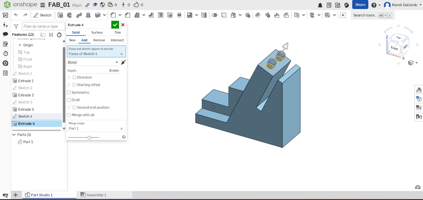
6. Finally, I created a Sketch a in the top of my figure and extruded two circles.
Result
3D Conclusion
Onshape and SolidWorks are similar CAD programs, but SolidWorks offers a wider range of advanced features, making it more comprehensive for complex projects. Onshape, on the other hand, is more intuitive and user-friendly. Personally, I consider SolidWorks to be the best option due to its greater level of professionalism and versatility.
Results
My Project piece
Steps for making the LEDCASE
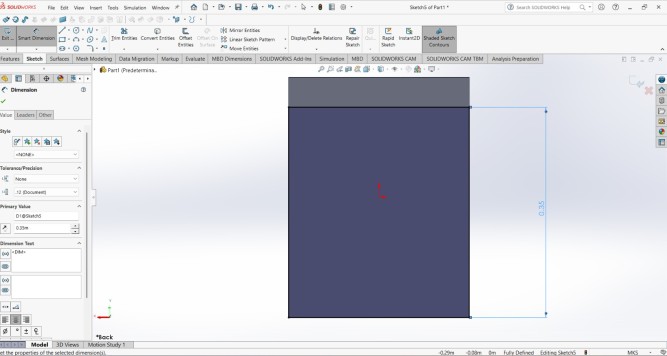
1. First I created a sketch in the front plane.
Steps for making the LEDCASE
2. Then I traced a center point rectangle and gave it a meassure of 30cm of lenght X 40 cm of height.
3. I extruded my piece 5 cm.
Steps for making the LEDCASE
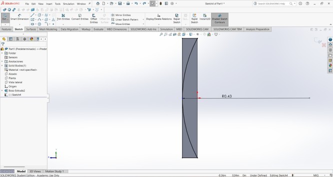
4. After that, I created a sketch on one side of the piece and made a 43 cm radius that touches both ends of the piece and closes both sides on the other side of the radius.
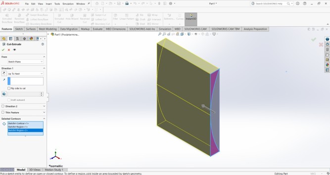
5. Then I extruded a cut in those closed sides.
Steps for making the LEDCASE
6.On the back, create another sketch and draw a rectangle measuring 30 cm wide by 35 cm high, leaving only the top edge. Making the complete piece also helped me to better define my idea of the complete structure.
7.Then I extruded another cut.
Steps for making the LEDCASE
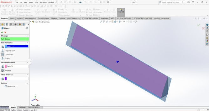
8. After extruding the cut, I made a sketch on the front, but to do that I needed to create a plane, so I used the plane tool and took the bottom line and the front face as a reference.
Steps for making the LEDCASE
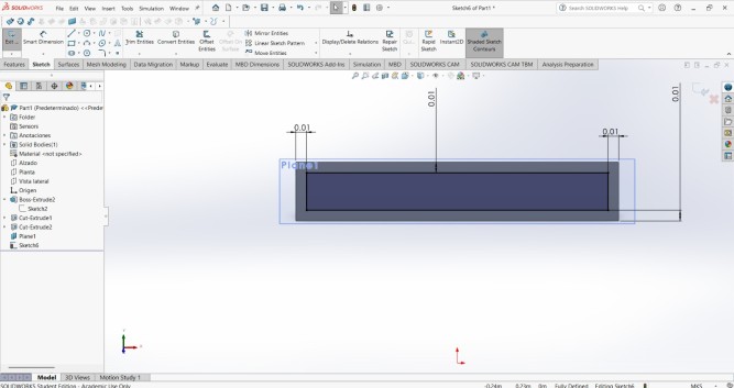
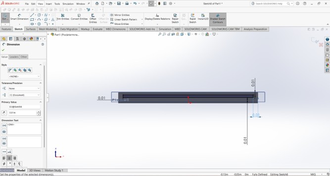
9. Next, I created another rectangle, gave it a distance of 1 cm from the ends, and applied an extrusion of 0.5 cm.
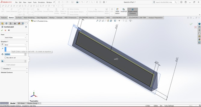
Steps for making the LEDCASE
10. I made a cut at the bottom of the piece to leave space for the cables. The interpasce is of 1 cm.
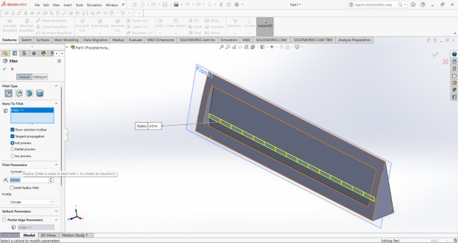
11. Then, in the interior I made a chamfer of 1 cm.
Steps for making the LEDCASE
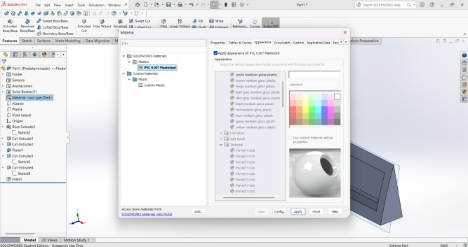
11. Then I applied a material to my piece, in this case I chose the only plastic that reflected light in my SOLIDWORKS version.
12. And I added an appearance to it.
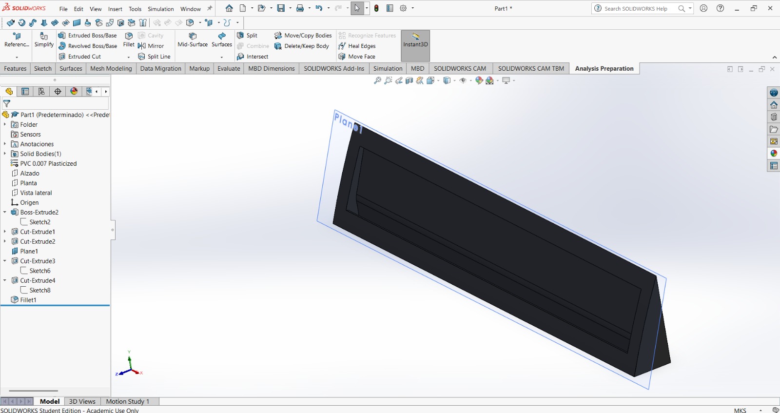
Result
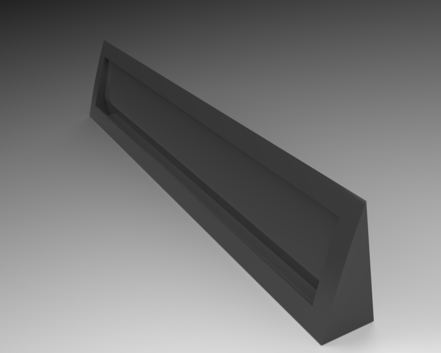
13. Finally, I made a render as I explained before, but this time I decided to change the perspective a little, and my work was finished.
Inkscape
Inkscape is a free, open-source vector graphics editor used to create and edit illustrations, diagrams, logos, and digital artwork. It uses Scalable Vector Graphics (SVG) as its native format, enabling infinite, lossless scaling, and serves as a versatile alternative to Adobe Illustrator.
HOMEPAGE
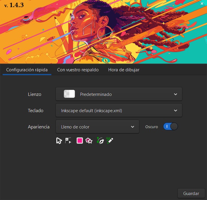
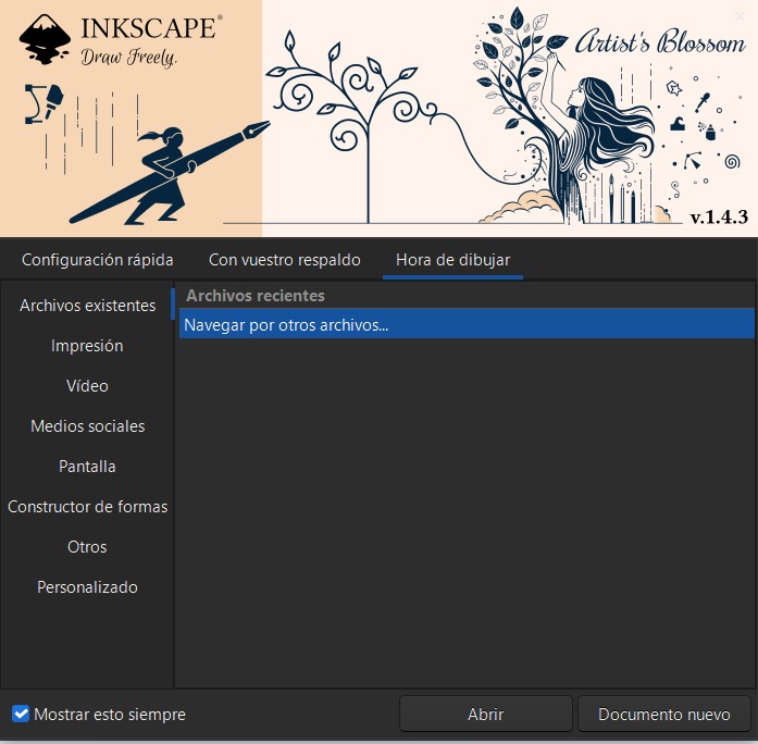
When you open Inkscape, a window will pop up. There you can create a new file and choose where to save it. You can also customize the appearance of the canvas, icons, and keyboard shortcuts.
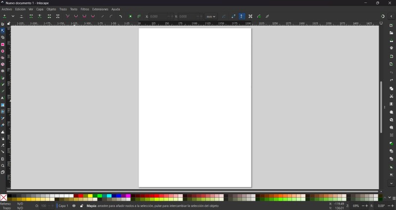
CANVAS
In the workspace, there is a canvas in the central area, a color palette in the lower section, and an overwhelming number of tools. I will limit myself to explaining how to vectorize an image, giving a brief description of the tools that I consider essential, and explaining how to reduce the size of an image using this platform.
Some useful tools
Selector tool:Select and transform objects.
Node tool: Edit paths by nodes.
Pen tool: Draw Bezier curves and straight lines.
Pencil tool: Draw freehand lines.
Import: Import a bitmap or SVG image into this document.
Open export: Export this document or a selection as PNG image.
Cut:Cut selection to clipboard.
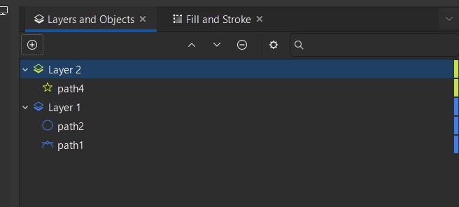
We can use layers to make our drawings more complex and detailed, which makes the work easier and reduces errors by separating elements into different levels, allowing us to view and correct them more easily.
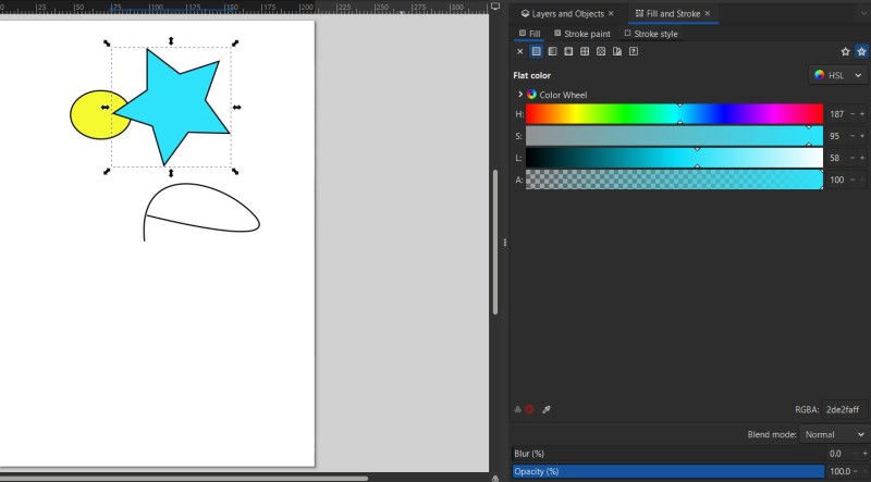
We can also change the fill of a stroke, including its opacity, color, blur, etc.
TRACE BITMAP
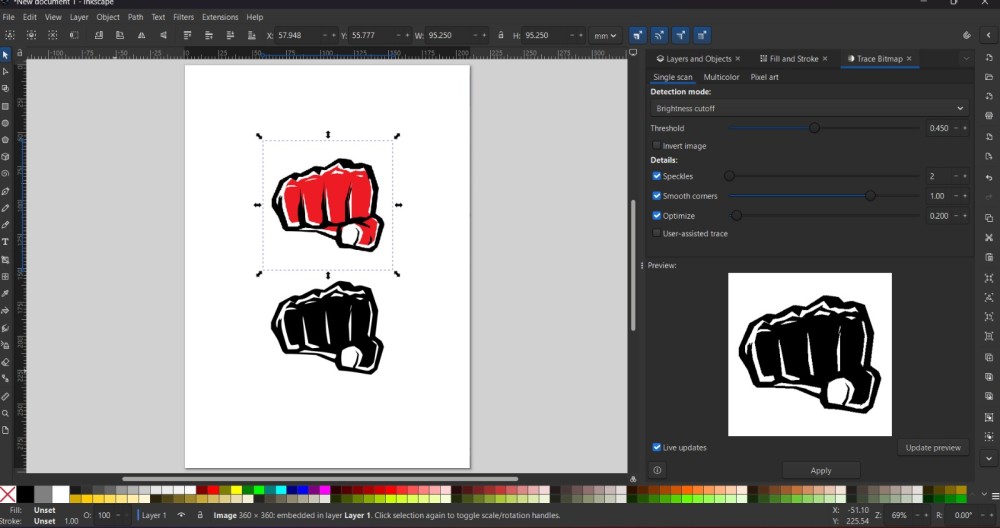
To vectorize an image we need to paste or import it into the canvas. I'm using a fist from the web.
Next, go to the Path section in the menu and select the Trace Bitmap function.
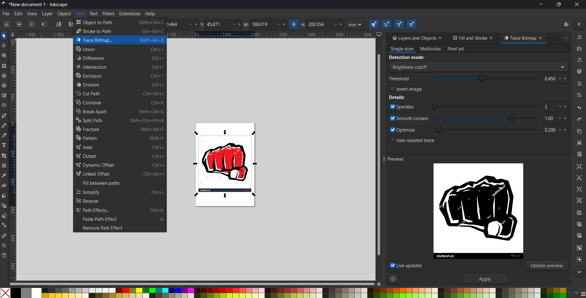
The Trace Bitmap option is used to convert pixel-based images, such as JPG or PNG files, into vector graphics.
This tool is especially useful for transforming hand-drawn sketches or downloaded logos into clean, editable lines and shapes.
To vectorize an image we clickApply. But if we want, we can edit the tresholds,the corners, optimize the vector, etc.
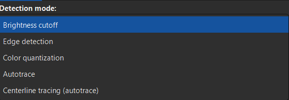
We can also choose the detection mode, between Brightness cutoff, Edge detection, Color Quantization, Autotrace, Centerline Tracing (autotrace).
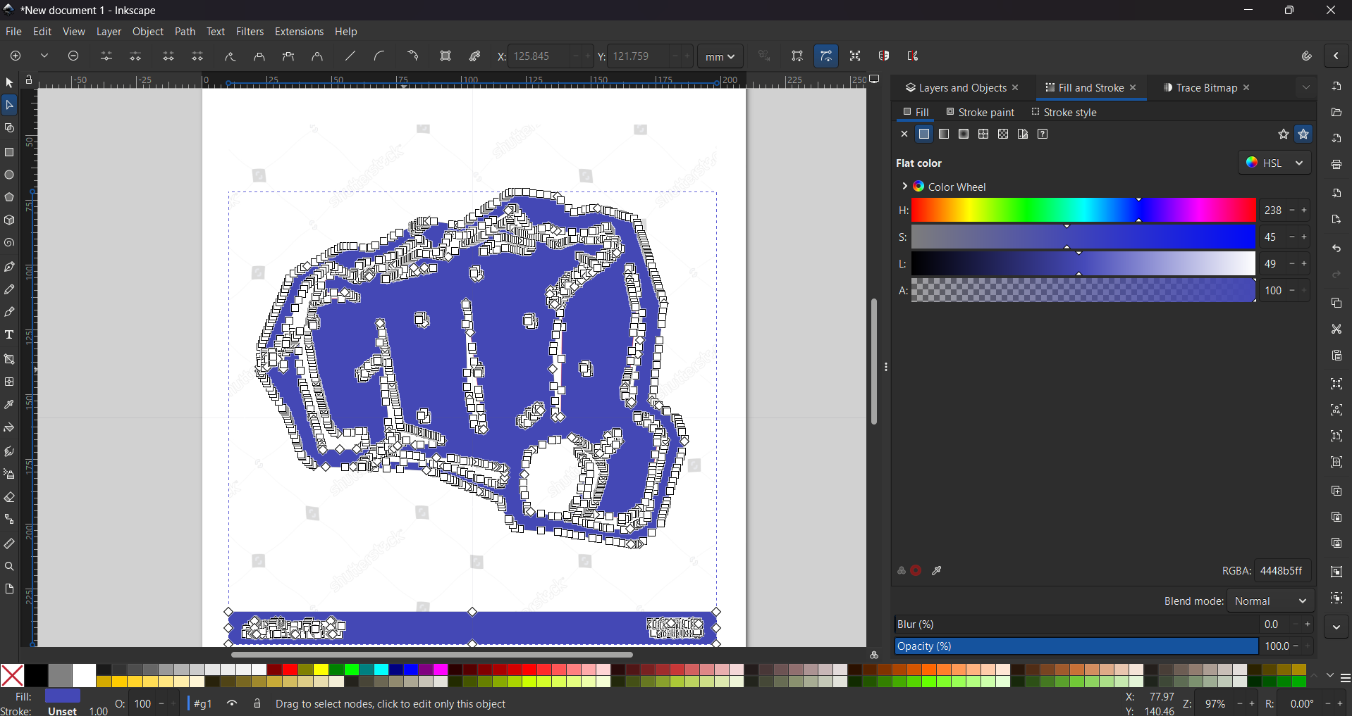
Once we vectorize the image, we edit it according to our preferences, and we end up with something like this. To add color we have to go to the Object section and click on Fill and Stroke. There we can change the colors of our image using the bars in that menu.
Results

Affinity
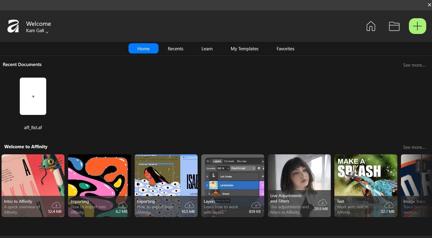
Affinity by Canva is a unified creative suite for photo editing, vector design, and layout, acquired by Canva in 2024.
When openning the software a menu will be deployed and we have to open a niew Canva by clickin in the top right button with a plus symbol.
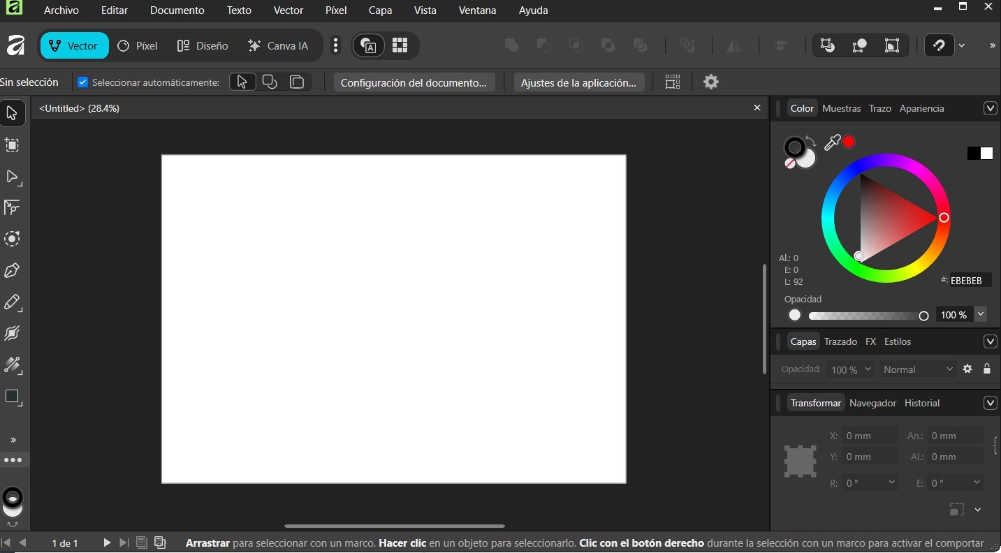
Just like in Inkscape, in the workspace there is a canvas in the central area, a color palette on the right-hand side, and a moderate number of tools.
Some useful tools
Selector tool: Select and transform objects.
Node tool: Edit paths by nodes.
Pen tool: Draw Bezier curves and straight lines.
Pencil tool: Draw freehand lines.
Vectorizing
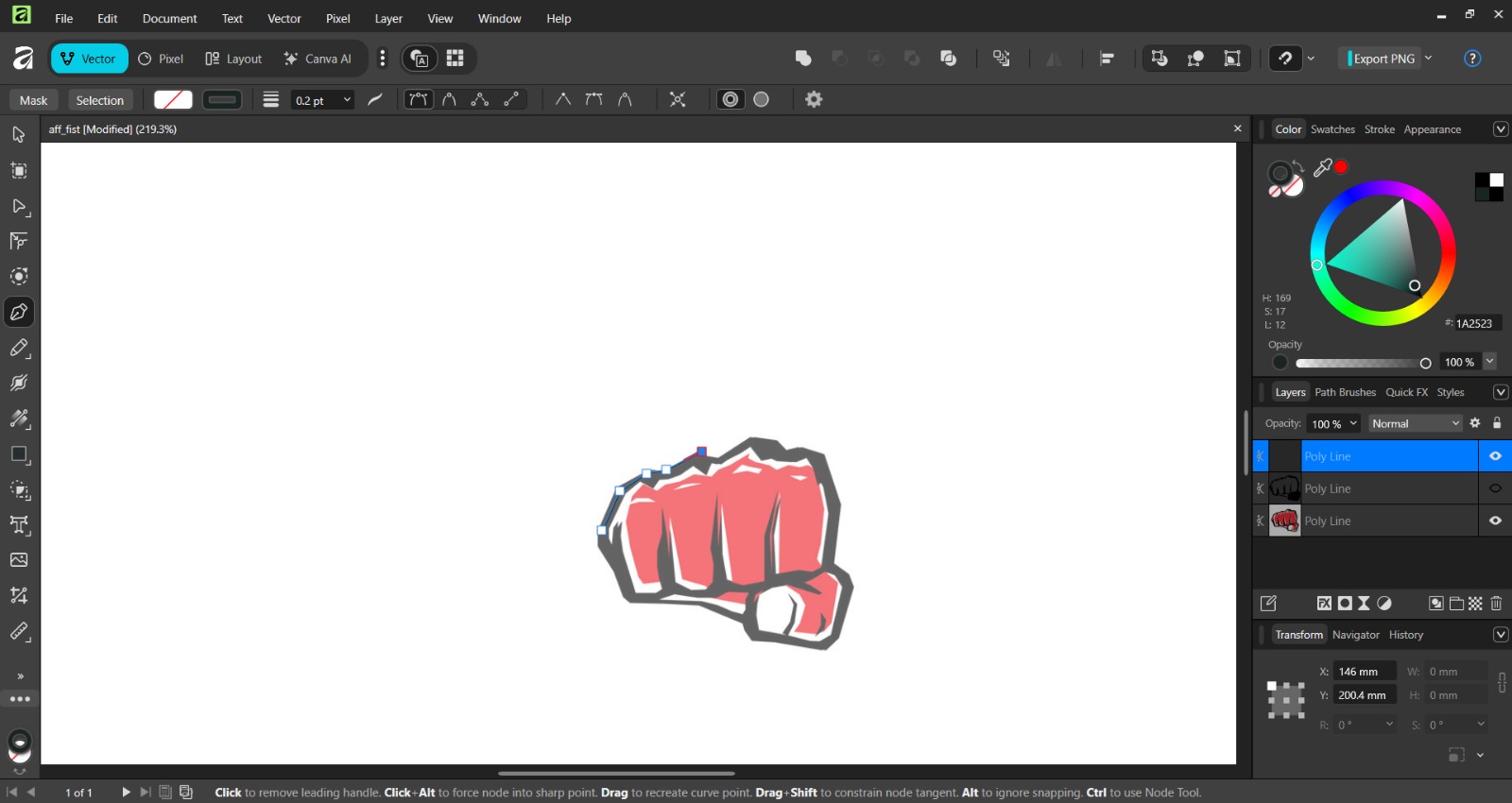
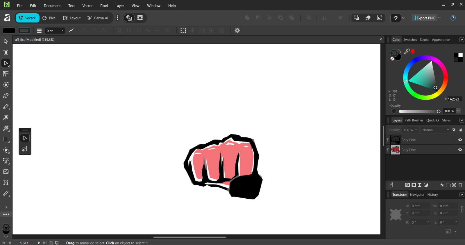
To vectorize an image in Affinity, I imported the same image I used in Inkscape, but this time I did the process manually. I lowered the opacity of the image to use it as a reference and began tracing using the Pen Tool in the left menu. To lower the opacitiy of an image, we have to go to the right side and click the layer of the image and low the opacity percentage.
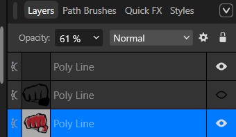
To close the trace we just have to click one of the previous nodes and the figure will be done.
Results

2D Conclusion
Inkscape and Affinity are very similar in terms of tools and functionality for vector design. However, in my opinion, Inkscape is better because the vectorization process is simpler and more immediate. Likewise, exporting an image is easier and more straightforward in Inkscape.
Compressing Images and videos
Images
For compressing images, I use Gimp. GIMP (GNU Image Manipulation Program) is a free, open-source raster graphics editor used primarily for image retouching, photo editing, and creating original artwork or graphic design.
Steps for compressing an image

1. First open Gimp in my desktop.
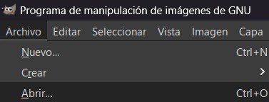
2. Then go to FILE in the left top corner and open the folder where the images we want to compress are. The next step is to select them all.
Steps for compressing an image
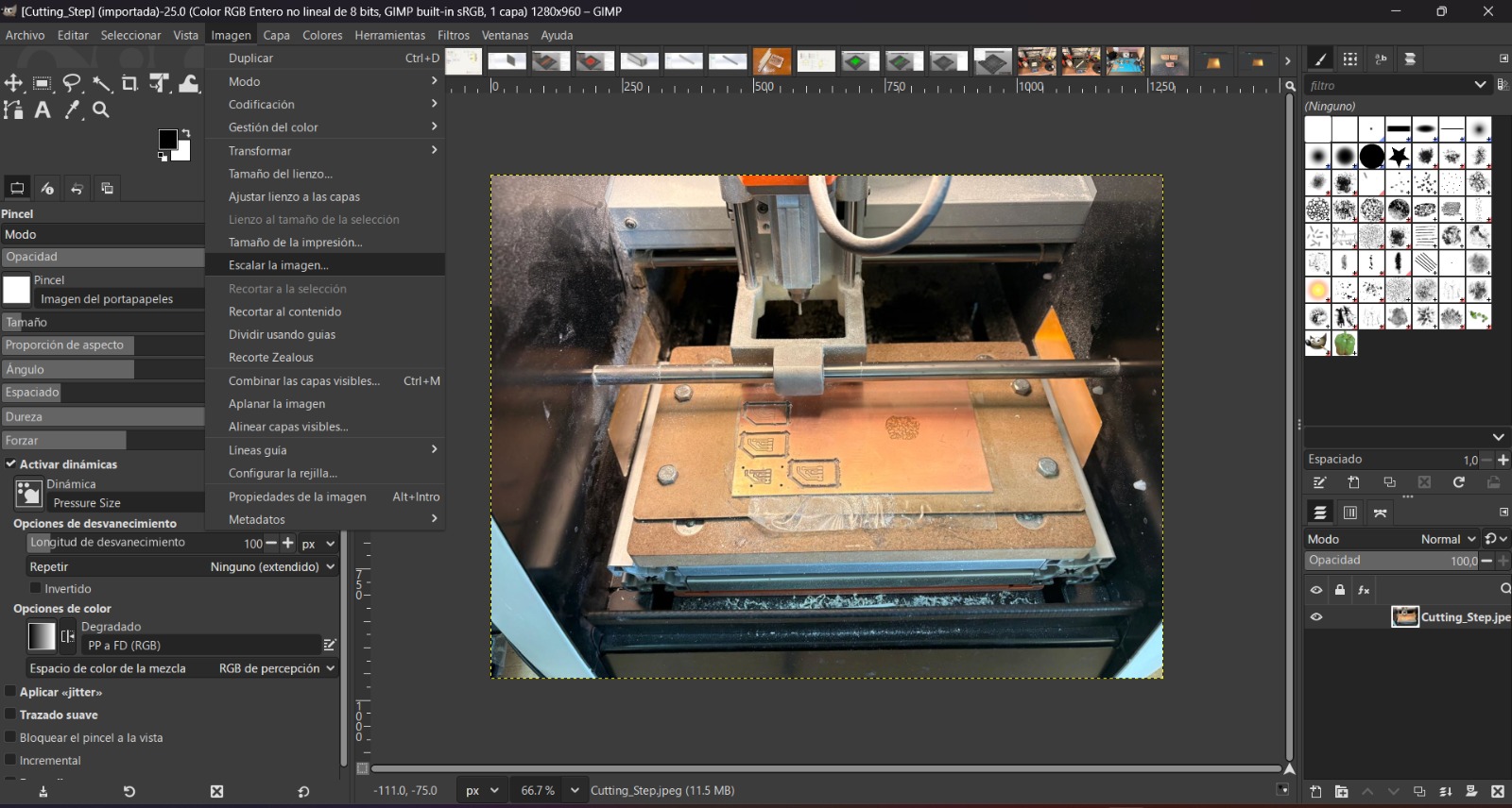
3. After opening the images, go to the top and click on image, then select Scale image.
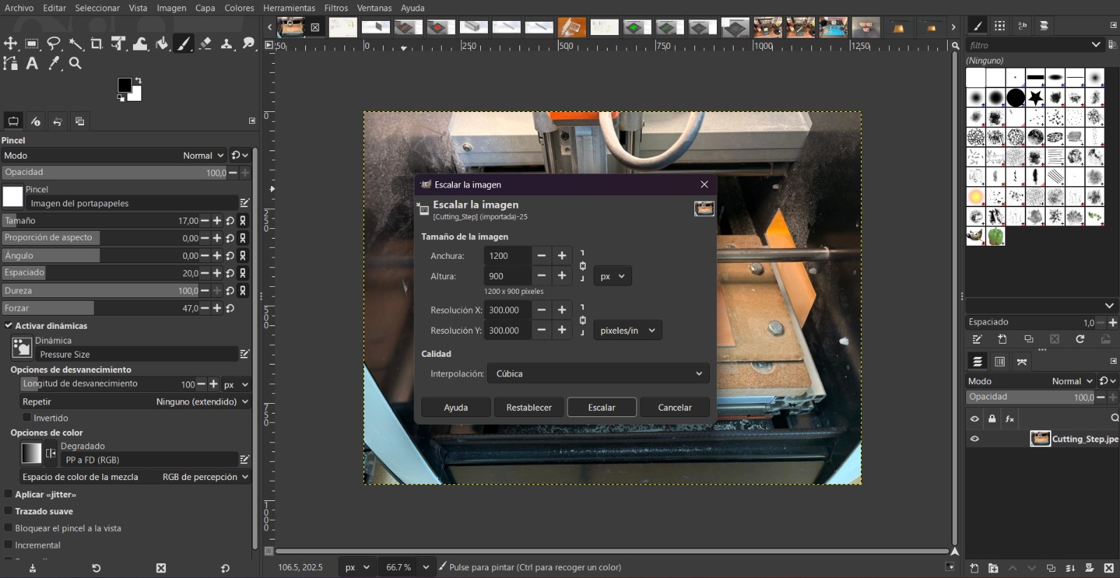
4.When resizing an image, you can adjust both the width and height. A good size range is around 1200 x 1200 pixels. I use the small arrow on the right side of both fields to set the width to 1200 and let the height adjust automatically.
Steps for compressing an image
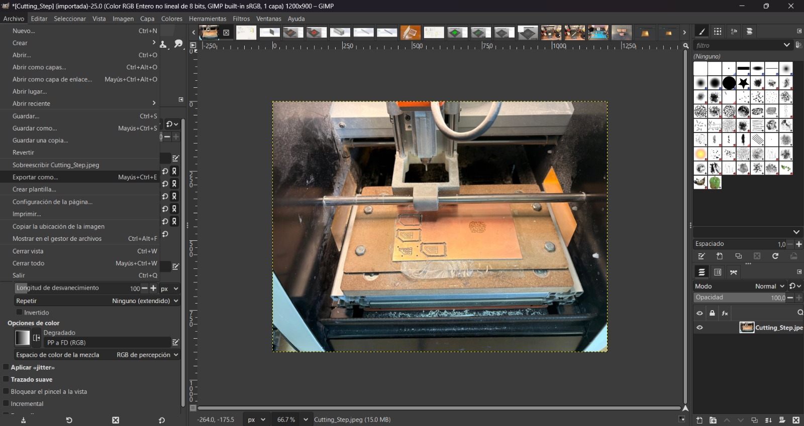
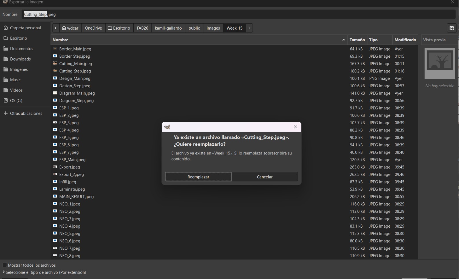
4. Then, we must go to File and select Export as. After that a window will open and there we can select where we want to save the image and change ints name. Usually, because I just want to compress my images, I just replaced the old image with this new one.
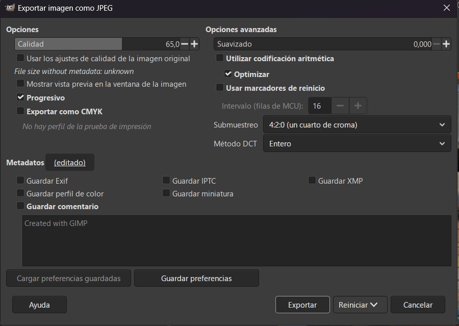
5. After replacing the image, another window will be shown and there, in the upper-left corner, there is a bar labeled “Quality,” so in that bar we need to set the image quality to between 65%–75%.
6. Finally, we have to click Export and our image will be compressed.
Videos
For compressing videos I used FFmpeg.
Steps for downloading FFmpeg
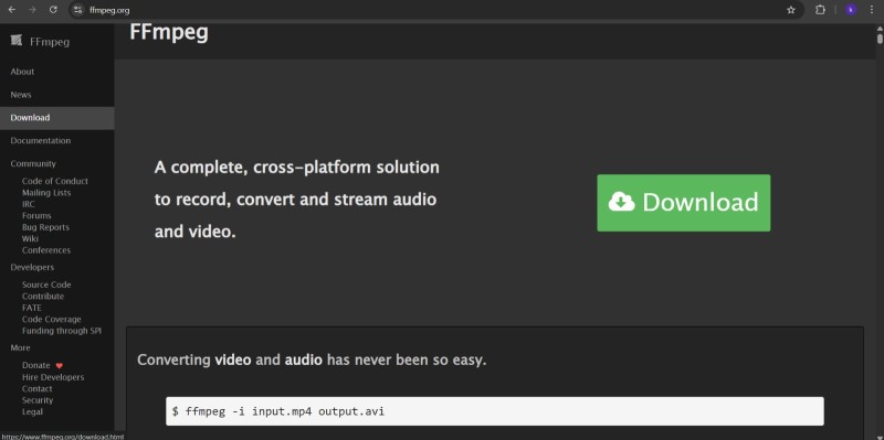
1. First open the link in my page or searching "FFmpeg" in the web.
2. Then open the download section.
Steps for downloading FFmpeg
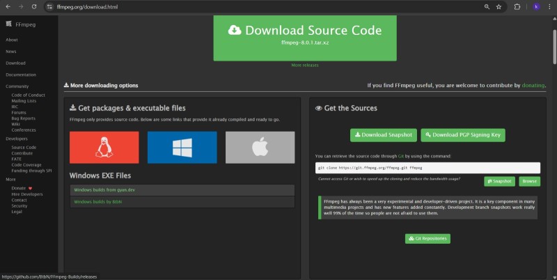
3. In the download section, we will find the different options for linux, Windows and mac. For Windows we need to open the BtbN version.
Steps for downloading FFmpeg
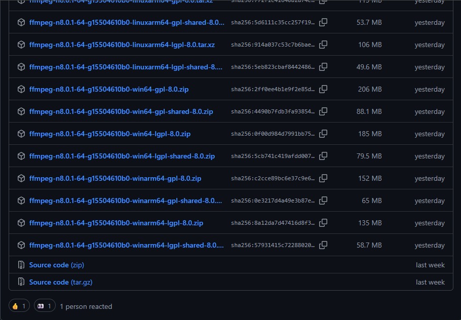
4. After opening BtbN, we'll now be in a repository, where we must look for ffmpeg-n8.0.1-64-g15504610b0-winarm64-lgpl-shared-8.0.zip and dowload it.
Steps for downloading FFmpeg
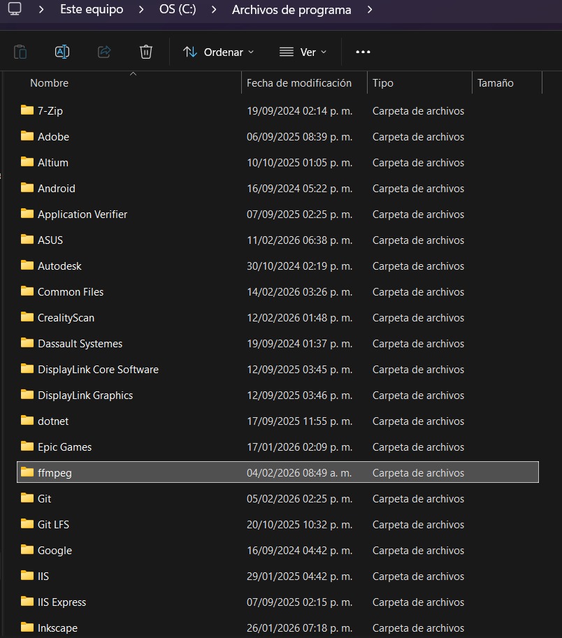
5. Then descompress the zip and save the file in Program Files.
To use FFmpeg, first you need to open cmd in your computer, then look for the folder in which you have your video, copy its dircetion and use the next command:
ffmpeg -i input.mp4 -vf "scale=-2:720" -c:v libx264 -preset slow -crf 30 -pix_fmt yuv420p -movflags +faststart -an output_new.mp4
ffmpeg -i input.mp4:Call the program and define the input file (videoname.mp4).
vf "scale=-2:720: Video resolution.
c:v libx264: Systems compatibility standard.
preset slow: Determine the compression speed; the slower the speed, the better the compression.
crf #: Constant Rate Factor (CRF) value for quality control. The range is from 0 to 51, where 0 is lossless and 51 is worst quality.
pix_fmt yuv420p: All browser compatibility.
movflags +faststart:Optimizes the video for streaming by placing metadata at the beginning of the file.
an:Removes audio from the output video.
output_new.mp4:Name of the output file.
Learning outcomes
This week, I learned a lot about part design and vectorization software. I already had experience with both SOLIDWORKS and Onshape, but this activity helped me better identify the advantages and limitations of each platform. SOLIDWORKS is significantly more powerful and includes a wider variety of advanced tools; however, it also comes with certain constraints related to computer performance, licensing, and software versions. In contrast, Onshape, as a cloud-based service, is continuously updated, places fewer demands on computer hardware, and offers a more intuitive interface.
Personally, I still prefer SOLIDWORKS because of its extensive capabilities and professional-level tools, although Onshape is a very practical option for less demanding projects or collaborative work environments.
I had never worked with Inkscape or Affinity before, and I found that both programs provide similar functionalities. Nevertheless, in my opinion, Inkscape is more intuitive and easier to learn due to its clearer workflow and specialized tools for vector editing.
Regarding video and image compression, I consider this to have been the most useful part of the week, since it allows me to manage storage more efficiently when handling large numbers of images and videos for documentation.
Finally, the piece I designed represents my first attempt at creating a housing to store and protect the LEDs that will indicate which pad to hit in my project. At the moment, the design is somewhat rudimentary, but I plan to refine and improve it in future iterations.