Week 7. Computer controlled machining
Summary
This week we focused on learning how to use the CNC machine to cut and engrave plywood and also vcarve to get our files to cut and engrave. Finally we made a furniture to demonstrate what has been learned.
Group assignment
Here is the group assignment to check more information about the topic computer controlled machining.
1. Basic concepts
1.1 What is a CNC machine?
A CNC (Computer Numerical Control) is a machine that is controlled by a computer to move a tool and cut, drill or engrave materials with great precision.
1.2 Programs used for scanning
This type of computer-aided design CAM software is primarily used for CNC machines. It allows you to import or create drawings vectors and convert them into toolpaths—that is, instructions that tell the machine how to move to cut or engrave a material. I used Vcarve so that is the one that I'm going to explain how to use.
1.3 Safety measures
To use this type of machine, we must use:
- Lab coat
- Boots
- Jeans
- Face mask
- Protective glasses
2. Design of the turntable table
2.1 Inspiration idea
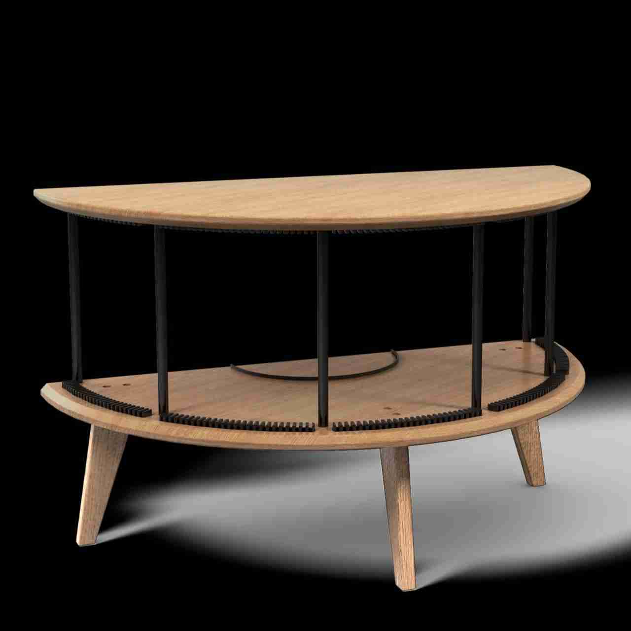
For this week I decided to make a table for my turntable. I started my vynil collection on autumn 2025 and I wanted that the vynils can be showed to everyone that enters in my house but all the furniture I saw on internet were always the same bored desing and the vynils were all hiden, that's why I decided to make my own table with the necessities that I had.
Inspired by a search at 2:00 am I found the Display LUNA by Kristian Juul design which had all that I wanted to exhibit my turntable and my vynil collection. So I tried to replicate that design. I also have to mention that I didn't buy this furniture because it is very expensive and out of my range (8,500 DKK that is pretty expensive).
2.2 Designing the table
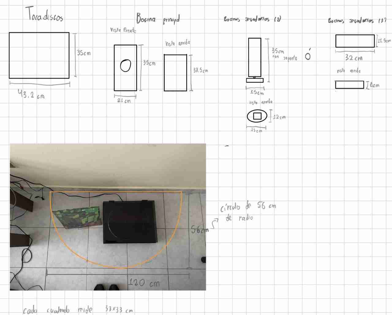
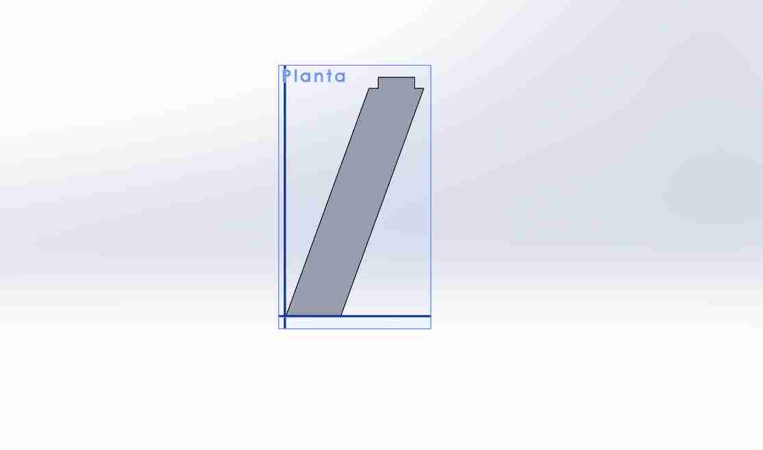
In my house I took measures of the space that I have and how it might look at the end.
I place my turntable and a vynil to see how it would look.
Finally I measure the space that the table will supposedly occupy to start designing.

Here are the measures that I took and drew.
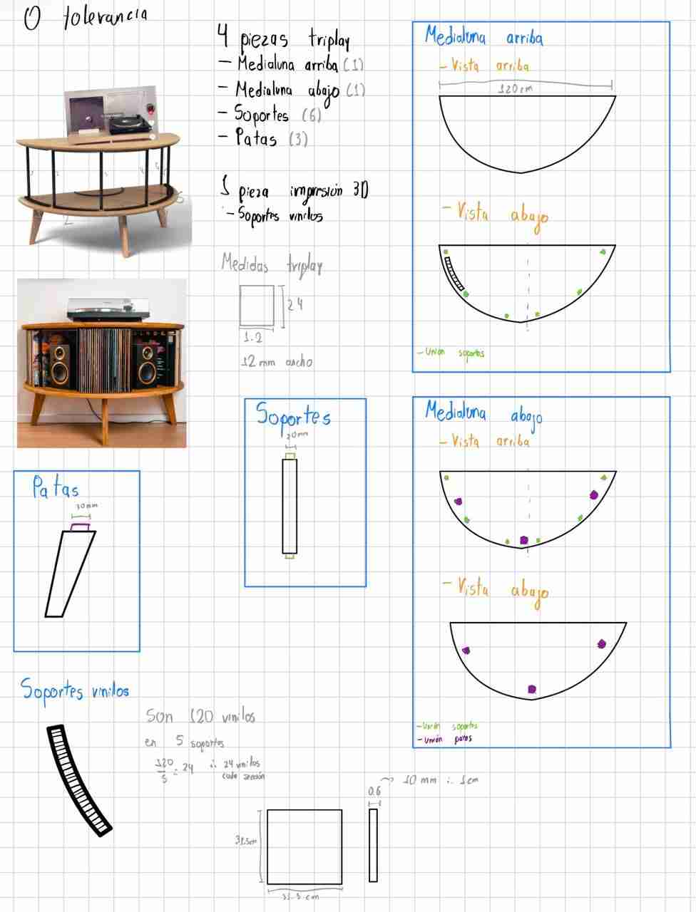
The CAM softwares accept dxf files to make the cut or engrave so I design and assemble the table in SolidWorks.
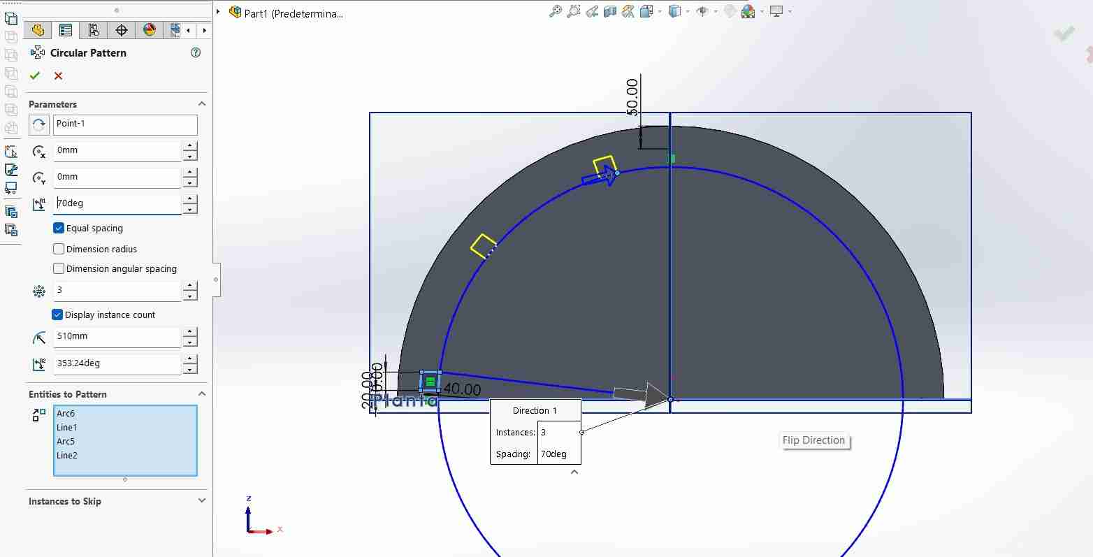
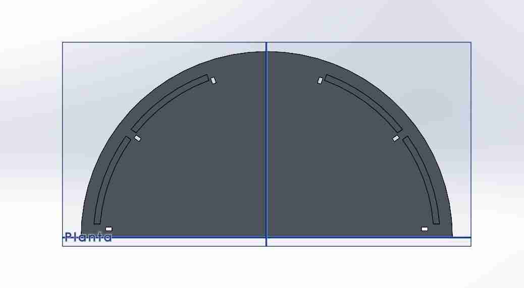
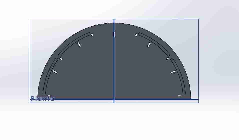
I first make the half circle and add it the joints with circular pattern for the supports between each half circle. And add it the engrave where the vinyl record holders will be.
For the supports bettwen I just make a square and add it the tabs for the joints.
For the bottom half circle copy and paste the already existing top half circle and just add the cuts of the tabs for the legs of the table.
For the legs I repeated the same process as the supports get the shape I wanted and add a tab for the joint.
For the vynil record holders I converted the entities of the engrave to extrude the piece, then I add it the cuts to place the vynils and make them as a circular pattern.
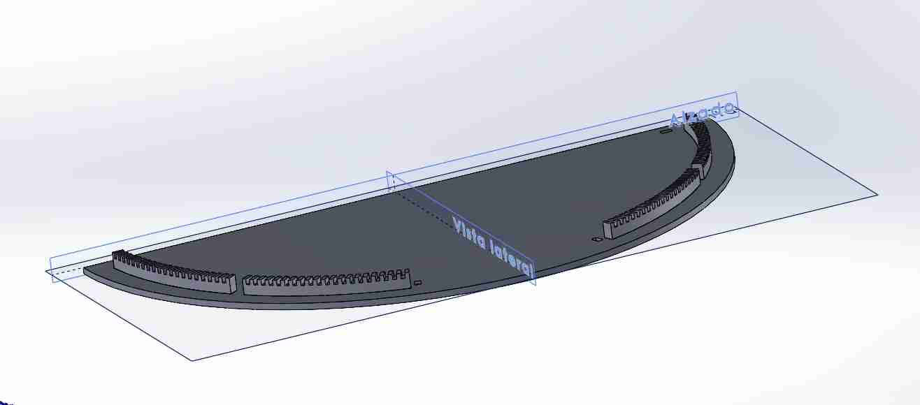
Last but not leas I added the half circle for the vynils to be on the same level height always.
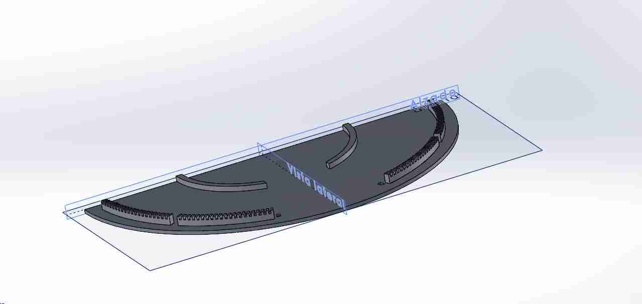
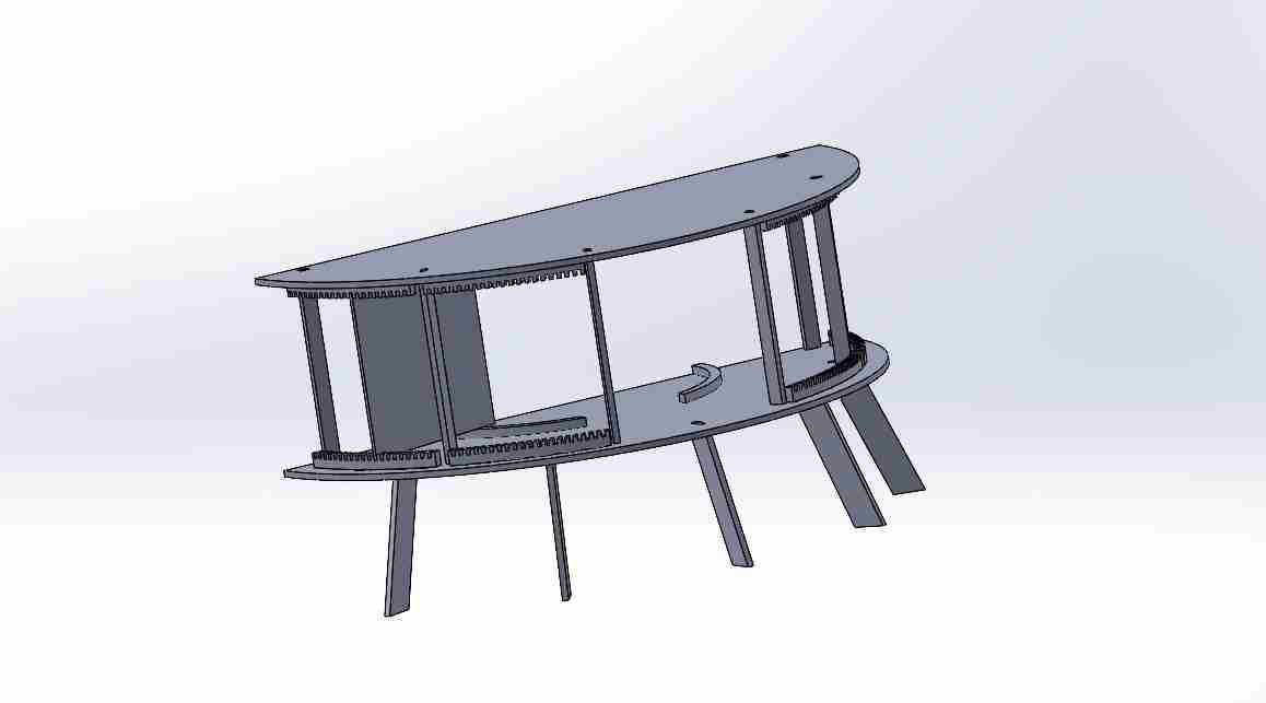
Here is how the table looks fully assembled.
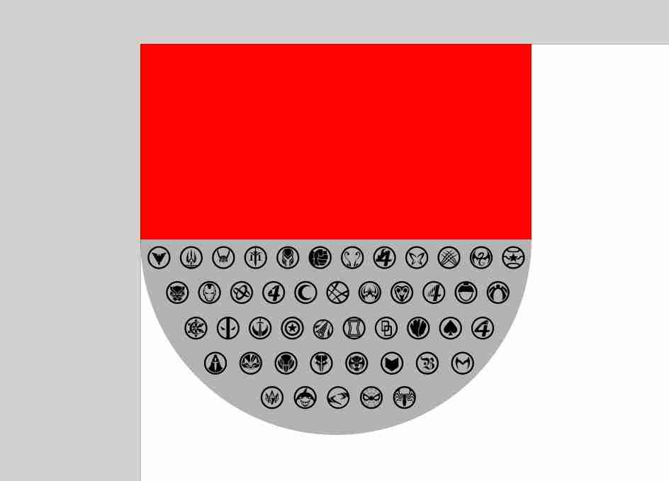
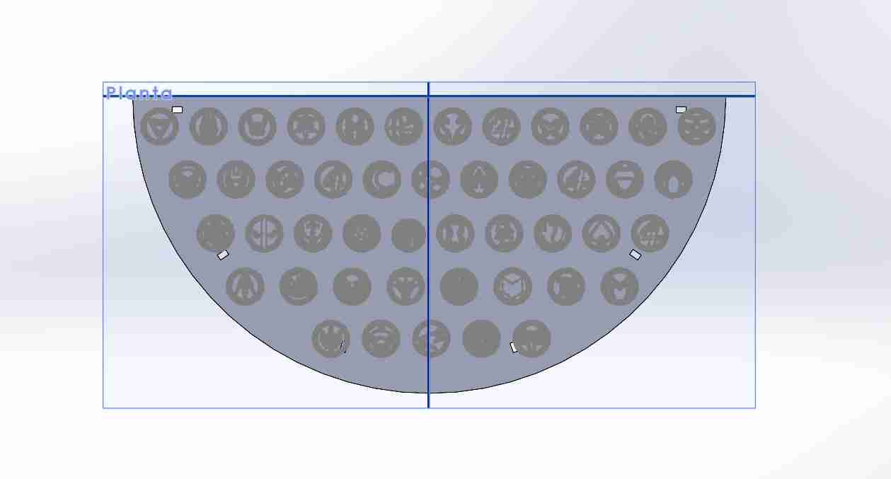
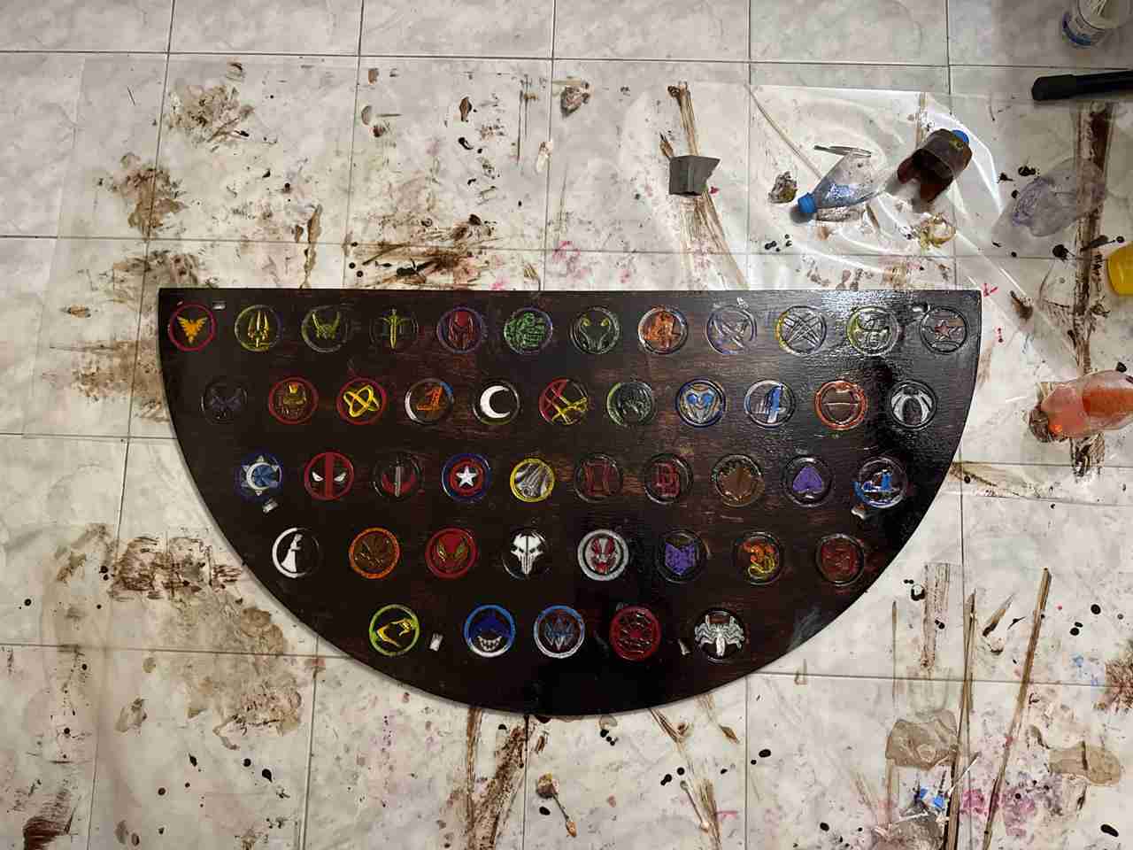
My personal touch was at the top, because I created a copy of the file above in case it went wrong or SolidWorks failed; there I added the logos of almost all the Marvel Rivals heroes.
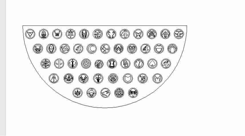
To avoid problems with SolidWorks, I created it in SolidWorks so that I only had to adjust the logo view in SolidWorks. In Inkscape, I added the furniture dimensions, vectorized the logos, and arranged them on the simulated table, resulting in the following.
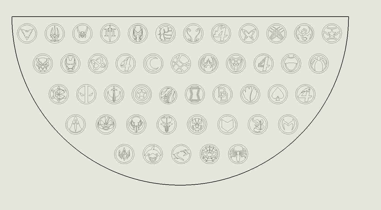
The I exported that dxf file to soliwdworks to add the engrave.
Here is the look in the dfx file.
3. How to use Vcarve
3.1 Open the programm
This is the logo of Vcarve we will click it and wait for the pc to open it.

What appears when we open our program.
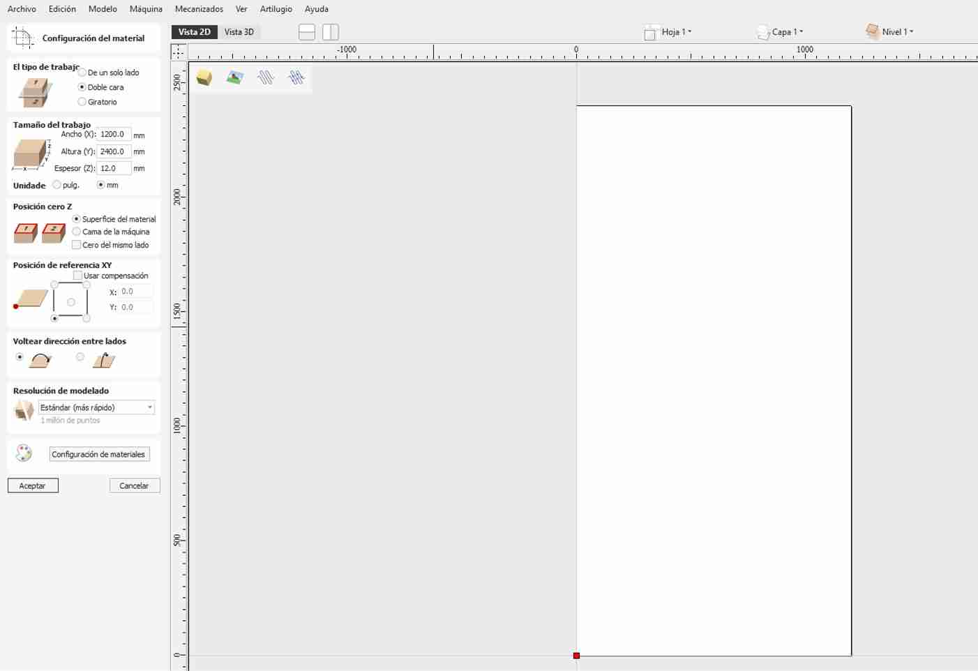
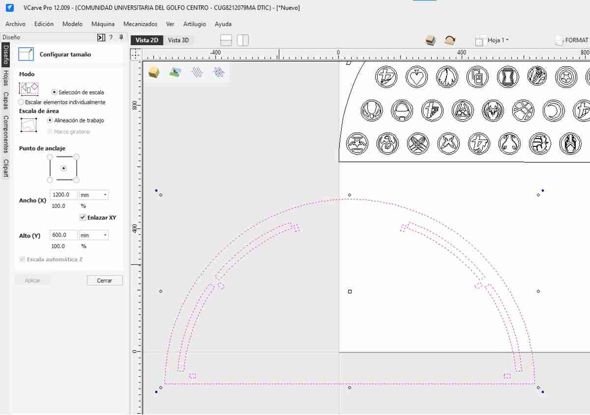
3.2 Configure the workspace
When you opne a new project Vcarve will automatically asl for the dimensions of your material, you just have write them and then click ok.
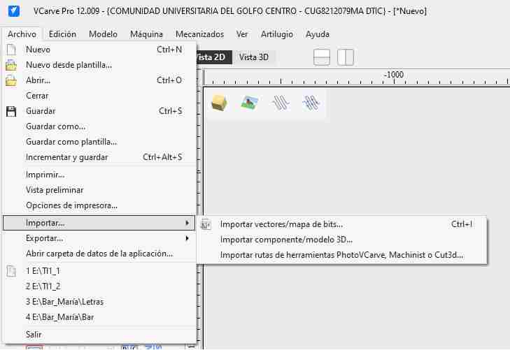
3.3 Import files
Let's import our file, import, import vectors/bitmap.
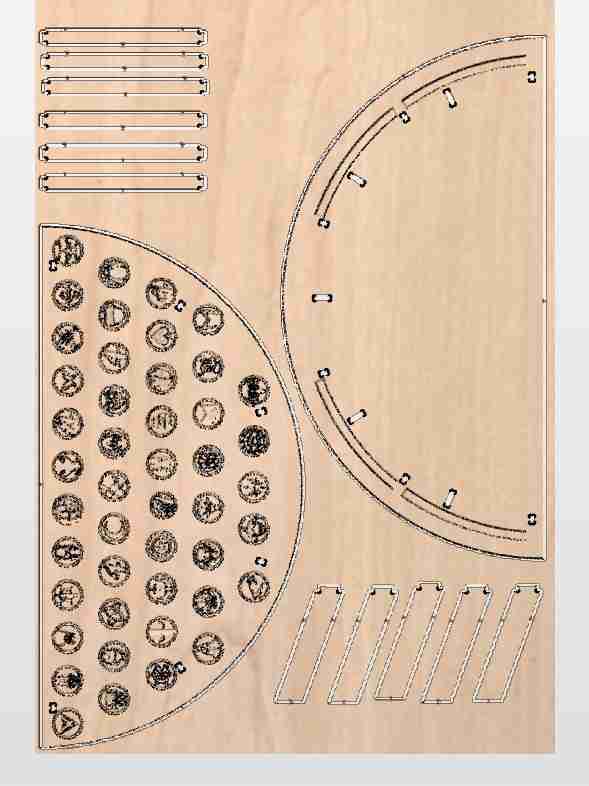
Here is how the file looks.
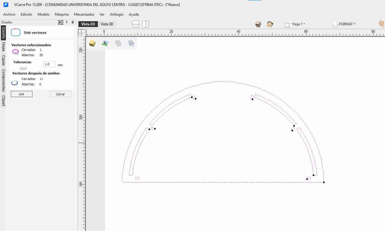
3.4 Join vectors
We will select all the vectar that we want to join, then click on the join icon (the square with rounded corners). We must joint them so is easire to work with them like moving them and adding "T-bones"
Tip: Allign your figure
If it's crooked, we use move and align it with respect to the axis
3.5 Set up cutting/engraving
We'll go to machine, then toolpath, and choose the type of cut or engraving we want to do. A tab at the right side will appear with the options.
3.5.1 Setting up the engraving for logos
For this engraving, I want it to be detailed, so it won't have much depth; that's why I'm choosing a depth of 1.8 mm.
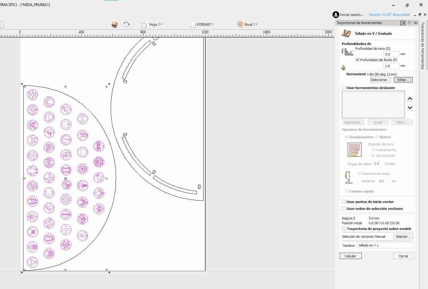
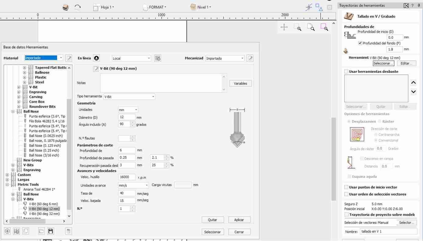
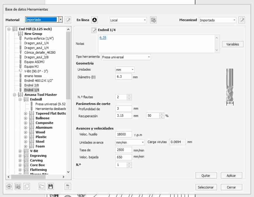
Going back to the details, I will use another type of drill bit that is 90 degrees and has a fine point. To modify this tool, we go to the edit button in the tool section and there we change the tool to V-bit and select 90 degrees with a diameter of 12 mm.
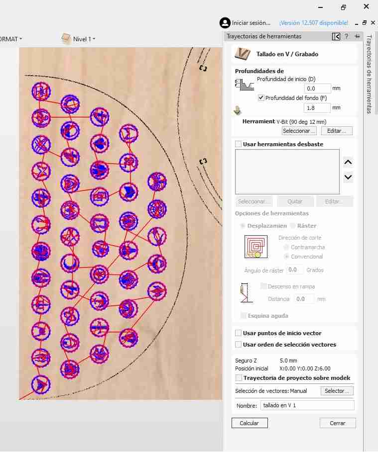
We click on simulate, we click accept and it will take us to another window that will show the entire route it will take.
3.5.2 Setting up the boxed with other tool
For making a boxed we select that option and for deep measure we input 2mm and select the boxed shapes. With this we have to change the tool like before, our tool is an Endmill 1/4 so we use that, we will also use this for the cutting.
3.5.3 Setting up the cutting
For this we will repeat the same proces as before but as we want to cut we will unport that we want to go 13mm down beacause our material is 12mm thick so in that way we ensure that it will be cutted. Then in the tabs button we click it and add 5 tabs so when it is almost cutted the machine leaves a small quantity of material so the material is not fully cutted in order to not get a piece crooked.
In total, I will have 4 types of cuts/engraving:
- Carving: We will engrave (in my case, the logos).
- Boxed: Makes holes.
- Inside: Makes the cuts for the joints.
- Outside: Makes the cuts on the outside to separate the parts of the furniture. In this option, it is important to add tabs because they prevent the cut from detaching completely from the material, ensuring it doesn't end up crooked.
3.6 Making the T-Bones
When you cut an internal square with a CNC, you have to make T-bones because the cutting tool (the milling cutter) is cylindrical and has a diameter, so it cannot create perfectly 90° internal corners.
T-bones are small circular extensions added to the inner corners of the design to accommodate the cutter radius, allowing square pieces to fit together correctly after cutting. In short, they are used to compensate for the geometric limitations of the CNC cutting tool.
For making them we will click on the create chamfers logo and then we click on the cornes, thay will automatically appear.
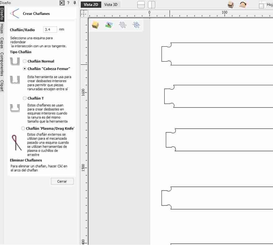
Here is the final result in 2D

Here is the final result on a 3D view or the material
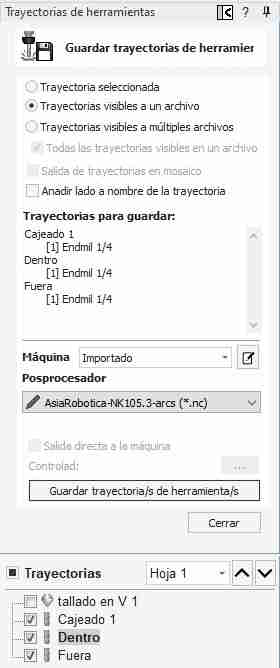
3.7 Save the route for the CNC
We will have 2 files for the instructions and remember to always start from in to out. We save both files the same way save a file in "AsiaRobotica 3-arcs", you have to select the option "visible paths of a file"
3. Using the router
3.1 Get your material
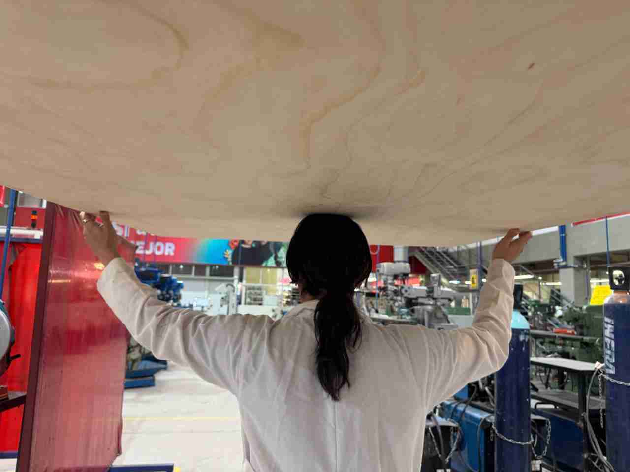
Move your material to the CNC
3.2 Turn on the machine
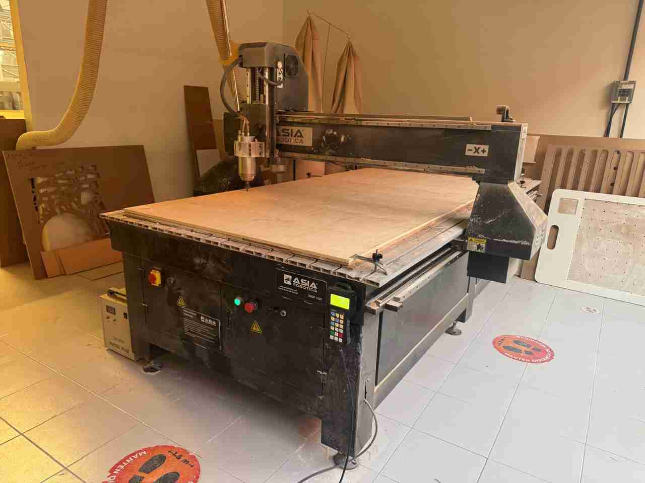
To turn on the machine, simply pull out the emergency stop button and press the power button to turn it on. I will use the ASIA Robotica machine
We can move our tool with the control buttons; using xy=0 will set our origin.
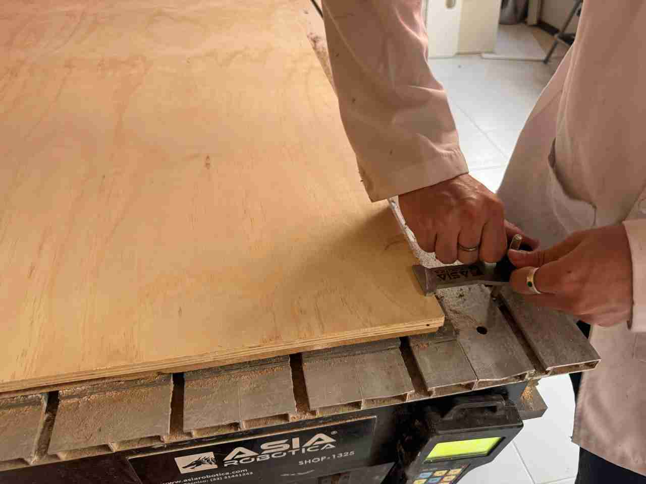
3.3 Place your material
We will place the material on top of the sacrificial bed.
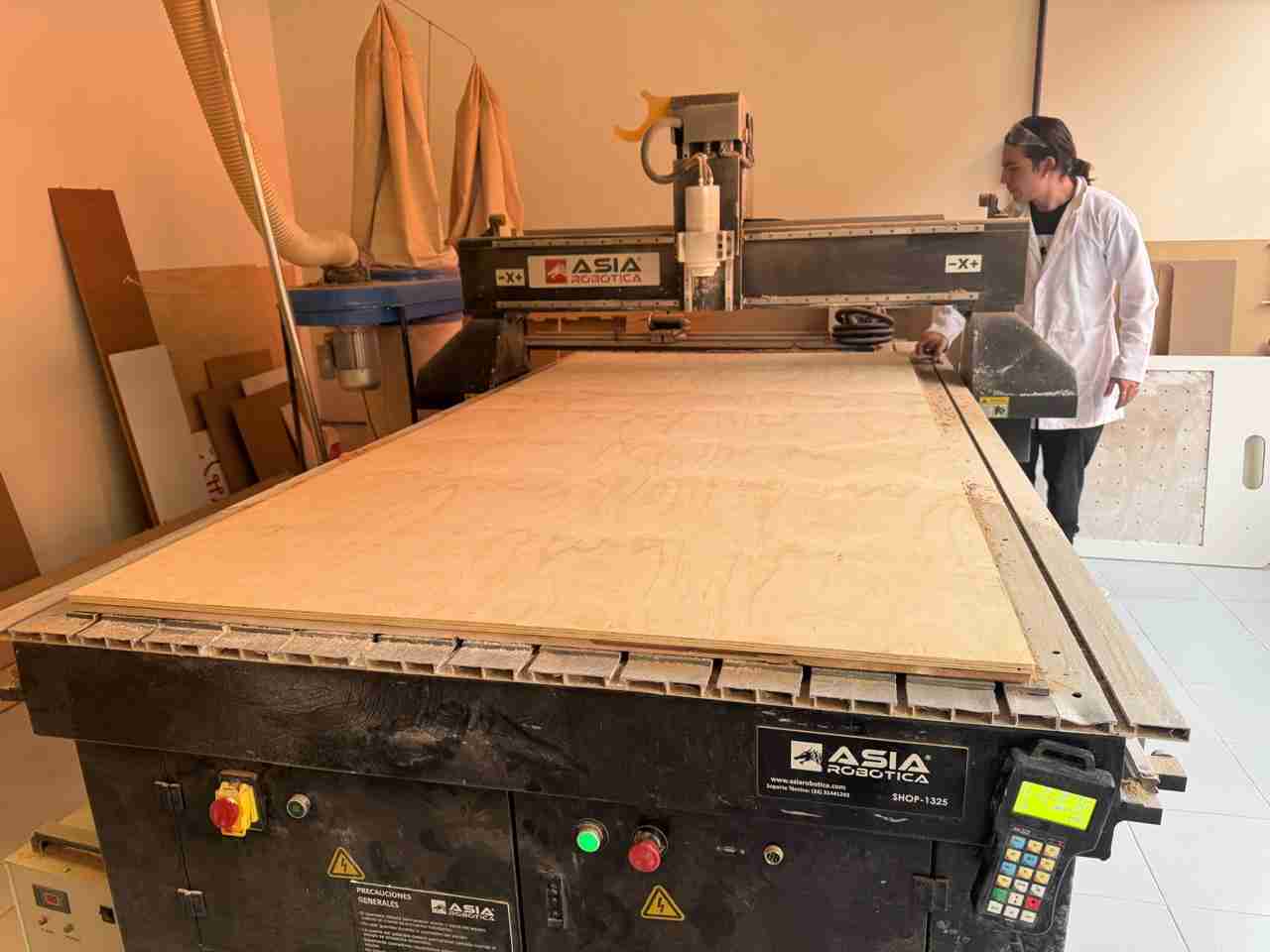
We put our locks or clamps on so that our plywood doesn't move.
3.4 Change the tool tip
We changed our tip so we could do the engraving first (because the order for the products to come out well is from the inside out)
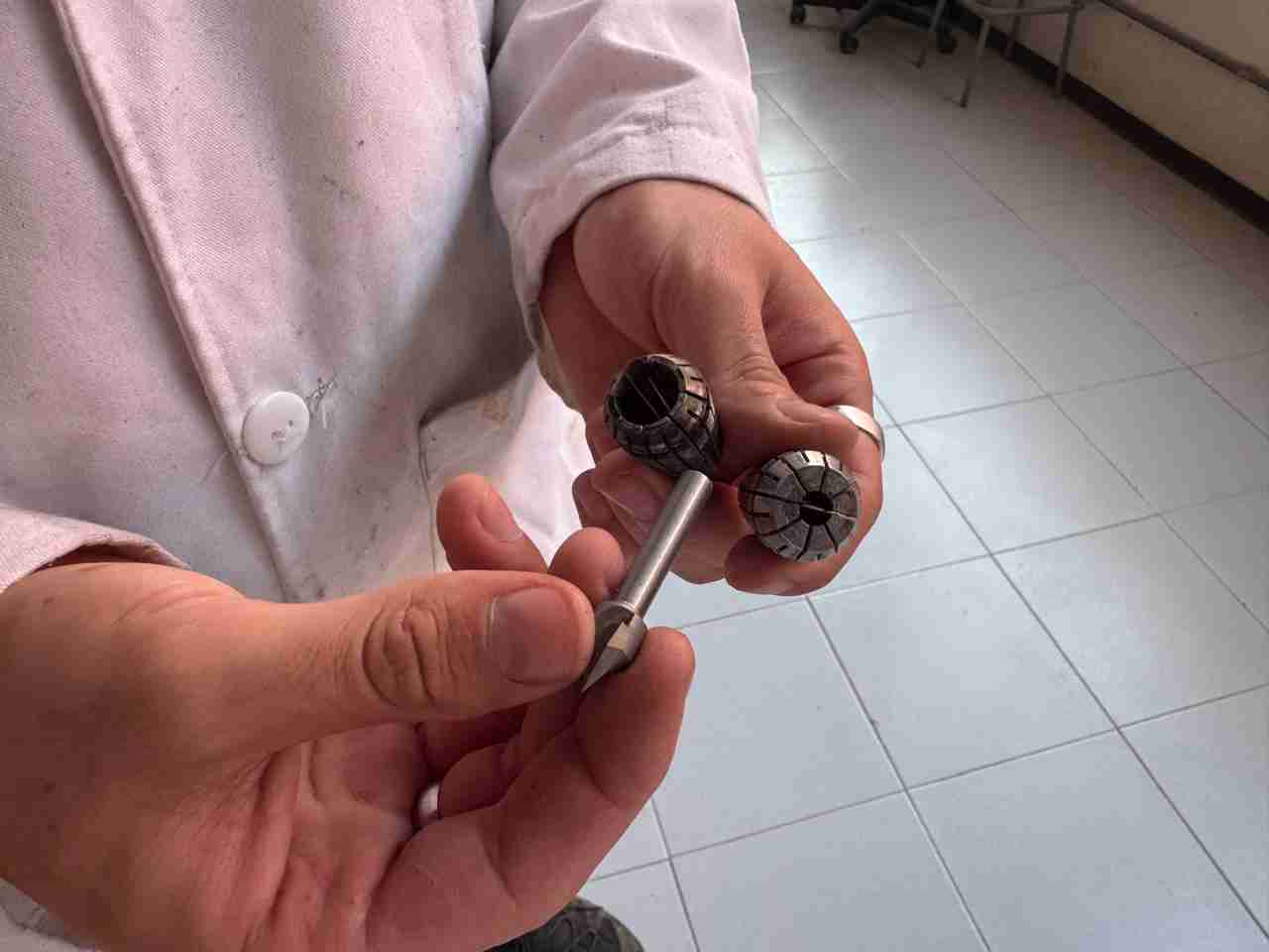
To change the tip, turn each nut in the opposite direction and the tip will come out.
3.5 Adjust the z axis
We manually adjusted our Z-axis tool because when we used it, the tool wasn't touching the plywood, so we had to adjust it. We simply loosened the screws holding the tool, and once it was at the required height, we readjusted them.
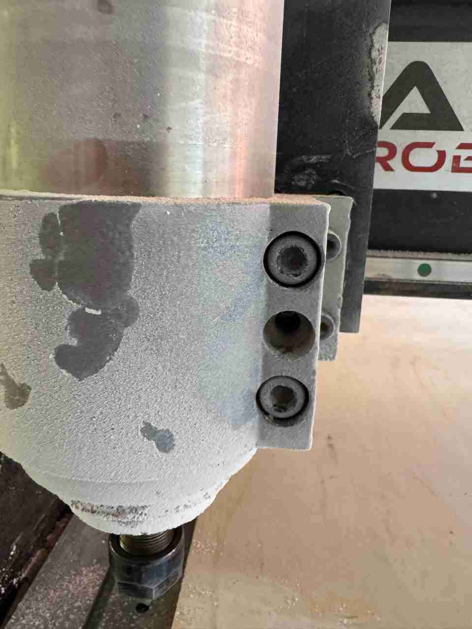
Now that is touching the plywood we can readjust the screws
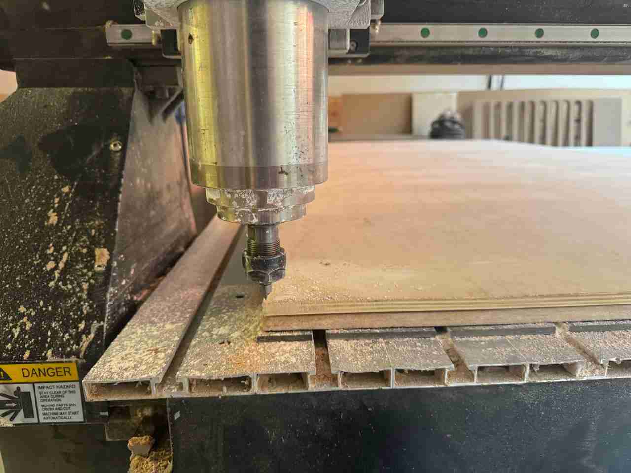
We'll do a short test to check that we're recording correctly. To do this, rotate the tool and slowly lower it to the desired depth. To set the origin to z, use shift+xy=0
3.6 Selecting our file
To use our file, insert your USB drive. The machine will detect and open it. Locate your file and select OK, then press 3 to copy it. Press Esc until you return to the first menu. Use the list button, select USB Files, find your file, select it, press 1 (load), and finally press play.
3.7 Start engraving and cutting
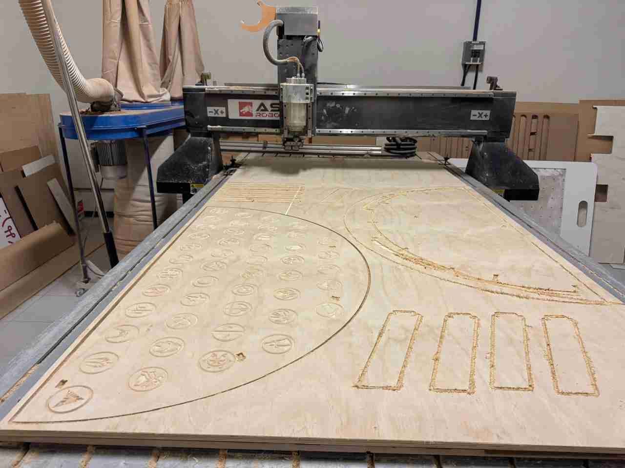
After it is calibrated we start engraving and the the cutting.
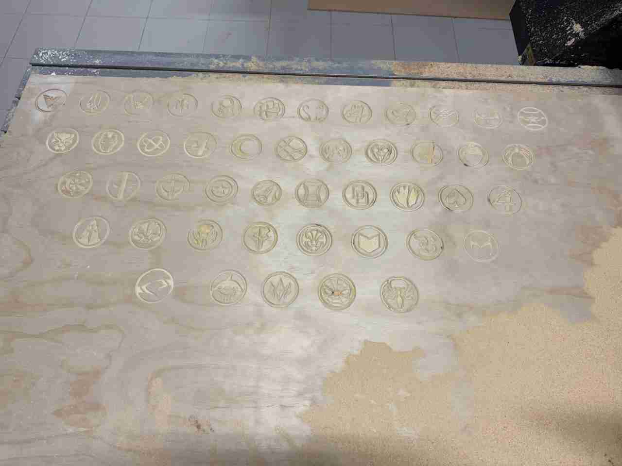
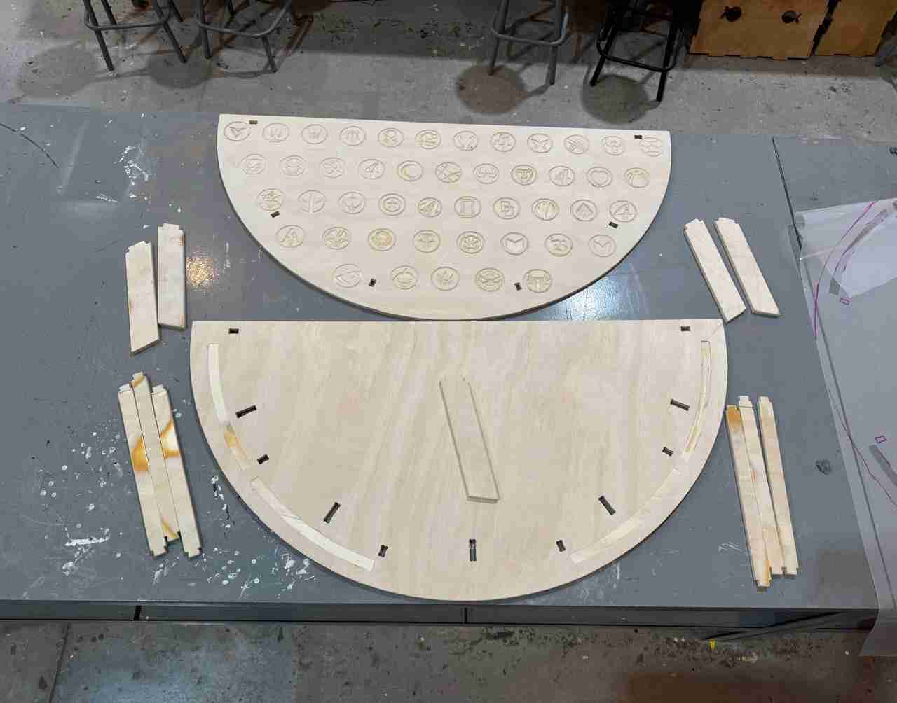
This is what the engraving of all the logos looks like.
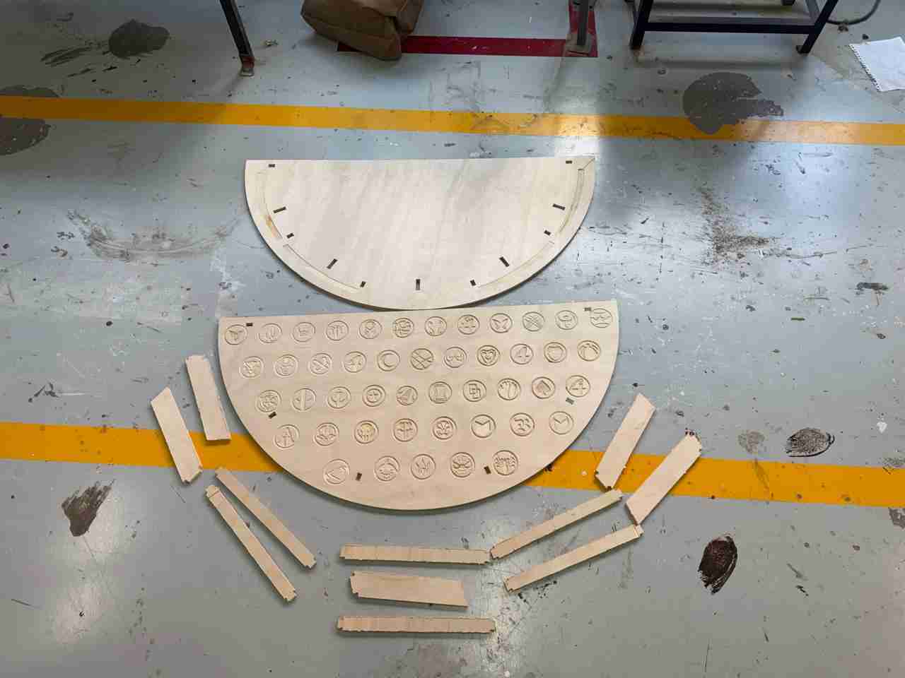
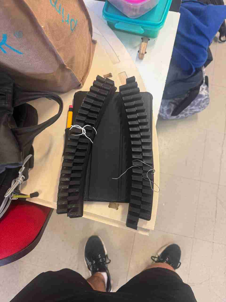
This is how the final pieces turned out.
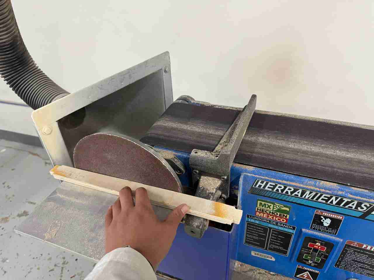
4. Post-processing
4.1 Sand your pieces
It is important to sand the pieces because it helps us to give a better finish when applying paint, stain, etc.
Remember to use all the safety equipment.
Here at Ibero we have a sanding machine with which I removed the wood burrs that had remained.
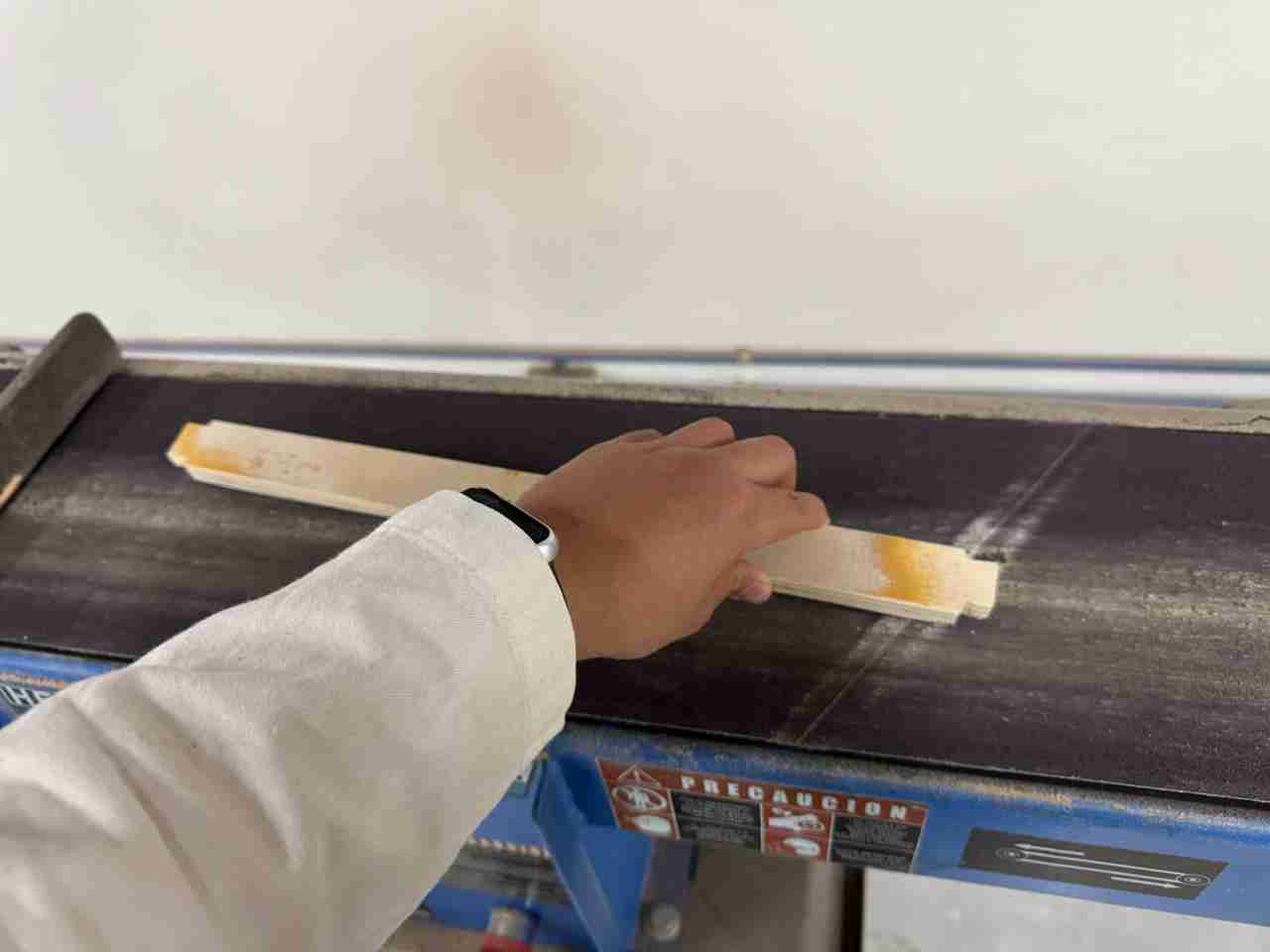
I have to do the sanding of the joints by hand.
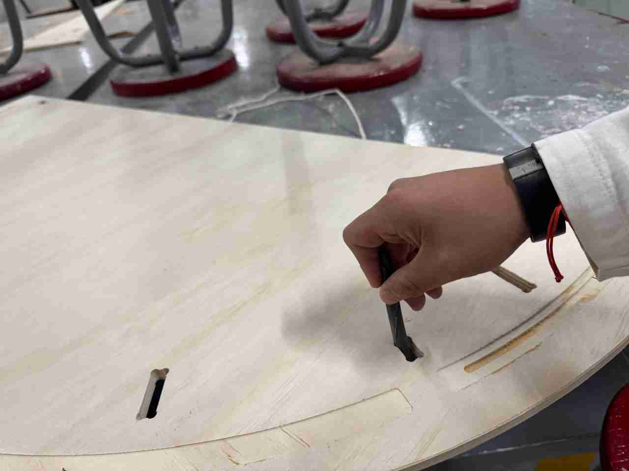
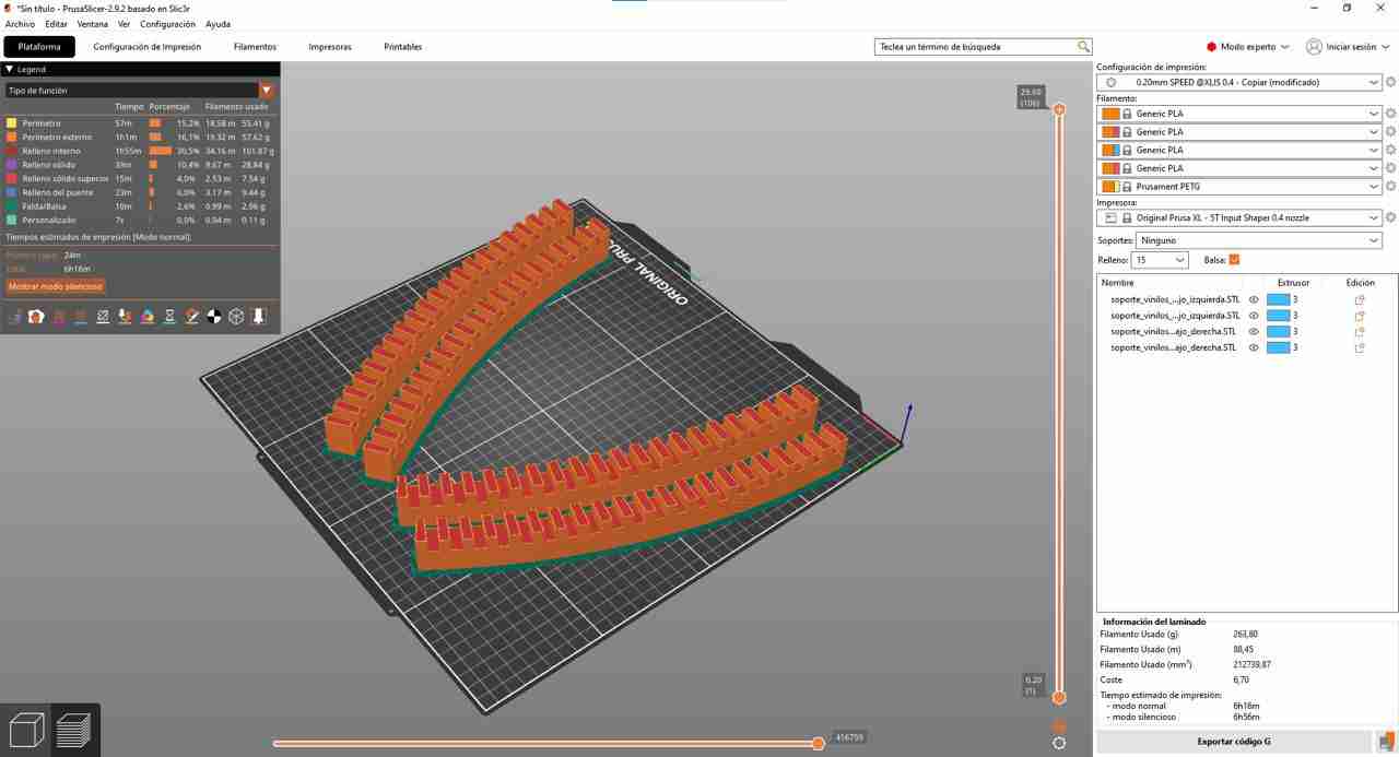
4.2 3D print the vynil supports
I 3D printed the vynil supports in a Prussa XL.
Finally, to close the pores, I used 400 grit sandpaper, and here is the result.
4.3 Paint the pieces
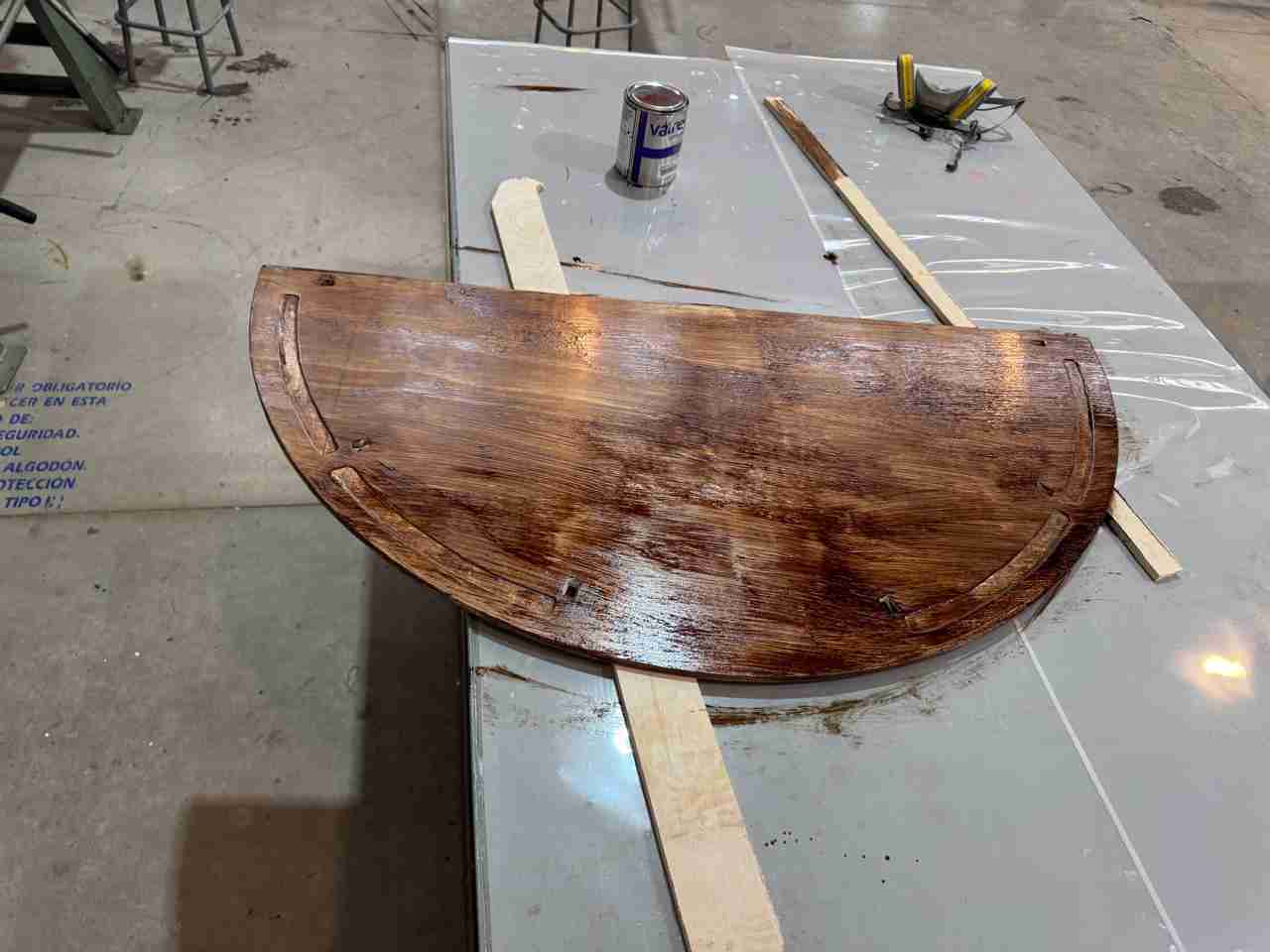
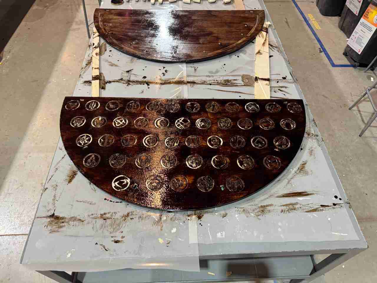
To paint, I used chocolate-colored oil paint, applying 3 coats.
1st coat
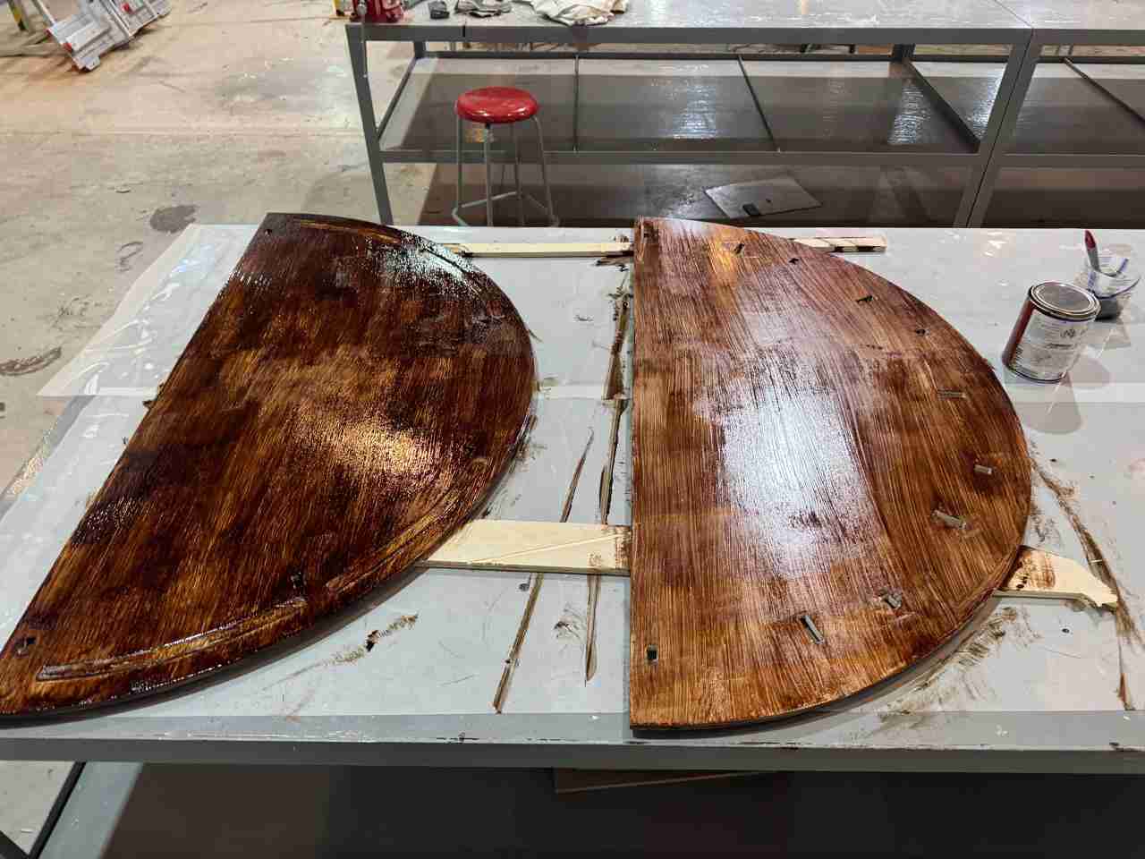
Comparisson with one layer and two layers.
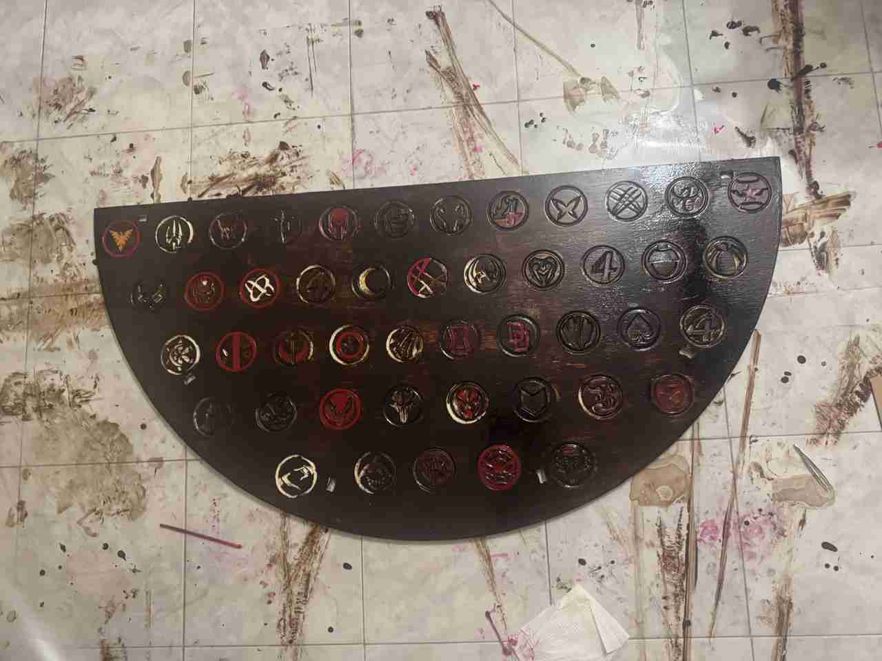
Here is how the top table look with 3 layers. For the top of the table, as suggested by a teacher, I will decorate it using colored crystal resin to paint each character's logo.
4.4 Apply the resin
For the top of the table, as suggested by a teacher, I will decorate it using colored crystal resin to paint each character's logo.
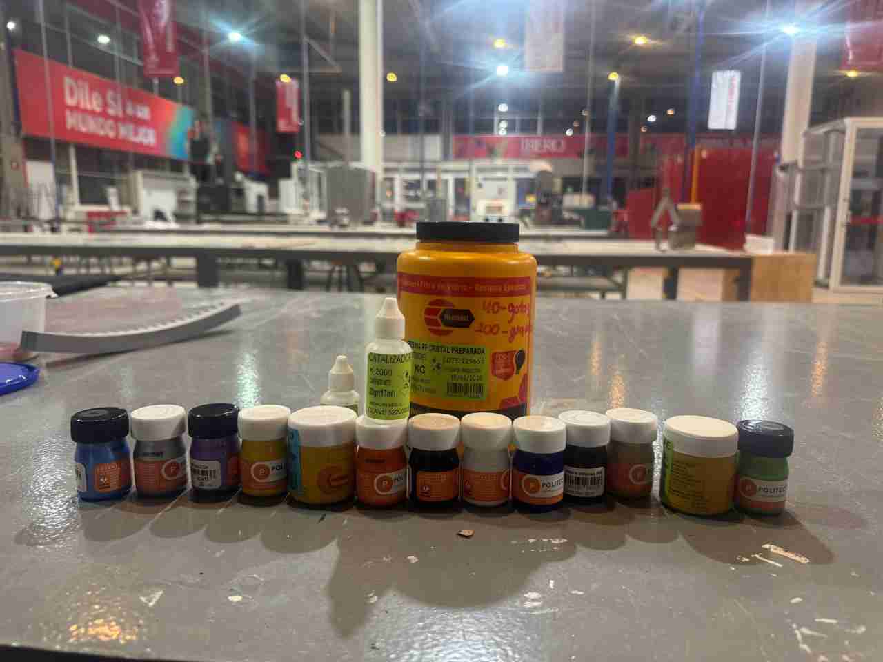
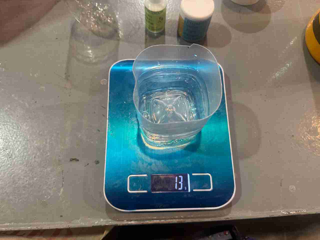
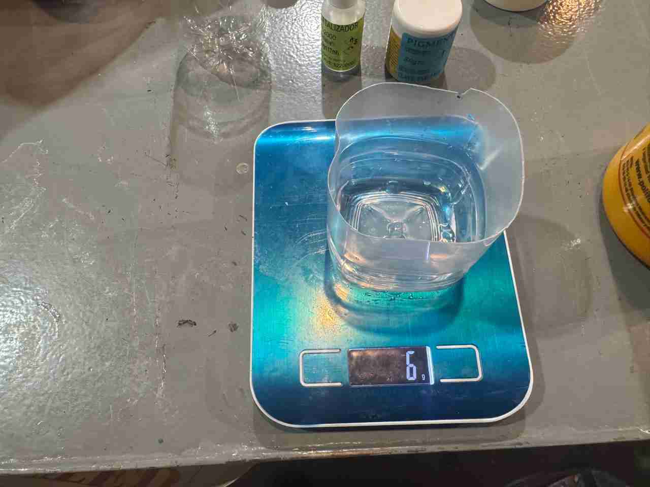
The manufacturer's instructions state that for every 100g of resin, 40 drops of catalyst are needed; therefore, since I prepared less of this mixture, I will use the corresponding number of drops.
Now I must emphasize that because I wanted to make a very small mixture, the catalyst couldn't act since the heat generated was absorbed by the container; that's why the photos show a very low weight.
Recomendatino for a small quantity of resin
So my recommendation is to make at least 30 grams; mix it from there, and it works perfectly, taking 30 minutes to dry if using pigment and 40 minutes to dry if using acrylic paint.
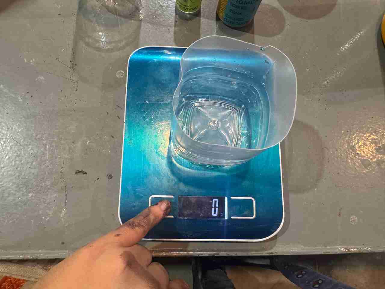
Add the amount of resin you need and calculate the corresponding proportions.
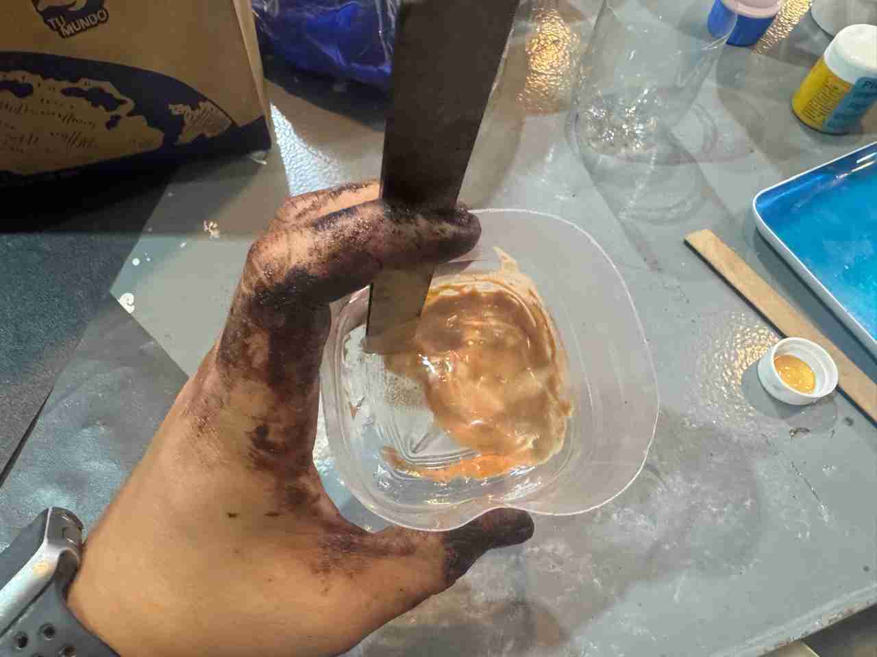
Once it's a homogeneous mix add the paint or pigment, add a small quantity if not the resin will not be cured and will never dry.
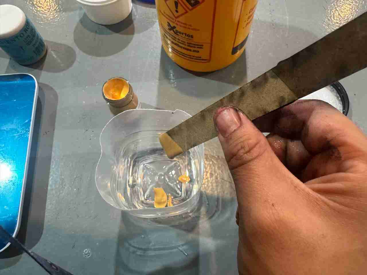
Then the resin is applied to each logo.
Here is a video of how the resin was applied.
This is the result of all the logos with resin
4.5 Assemble the table
Start with the legs for the bottom table, press them and fit them.
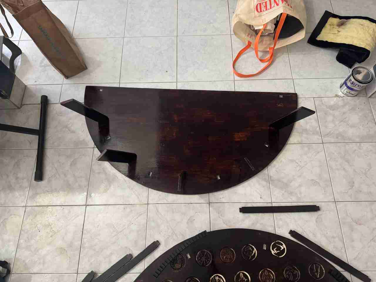
Then join the supports as same as the legs press them and fit them.
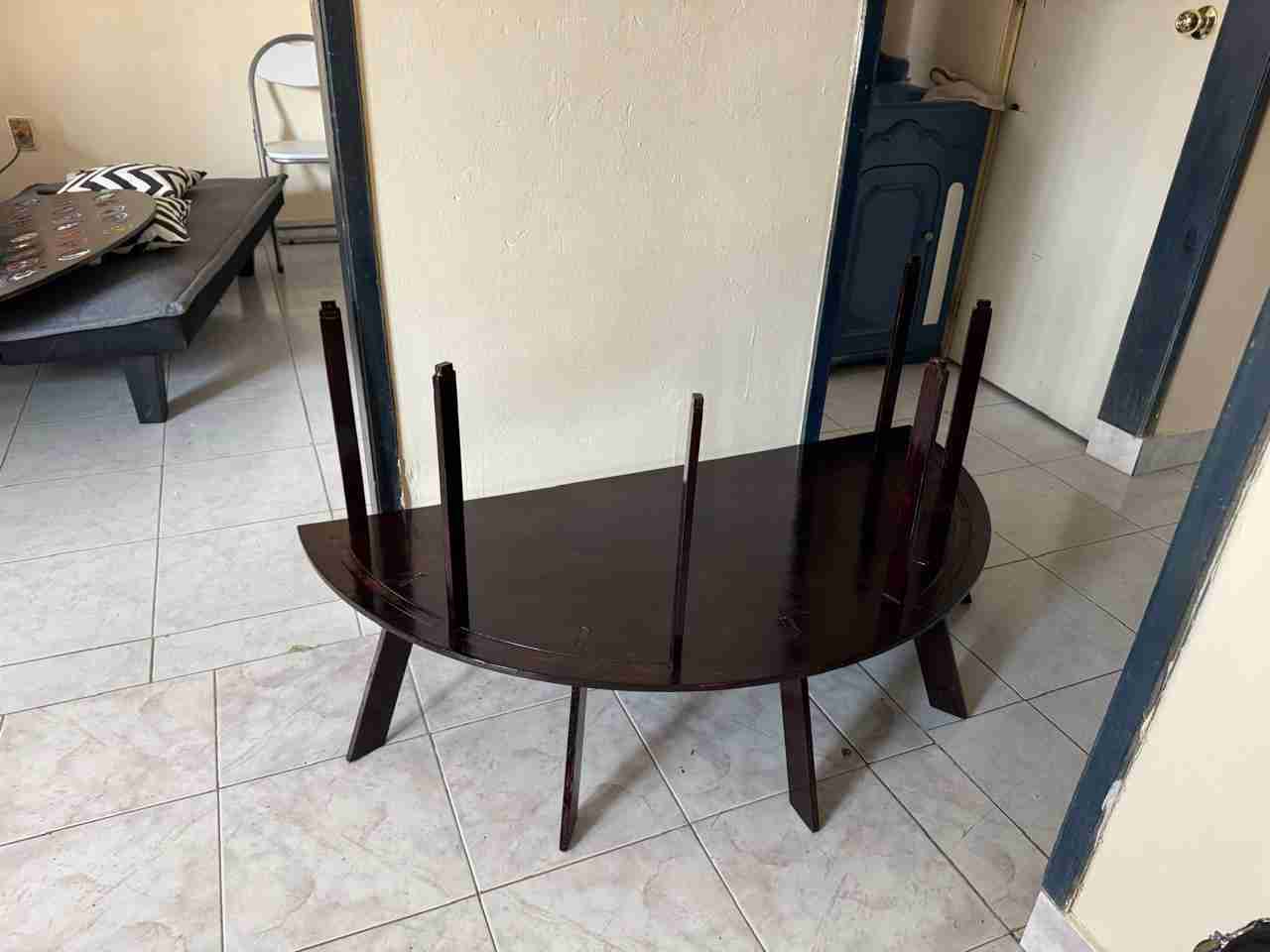
Then fit the turntable supports assembled onto the table.
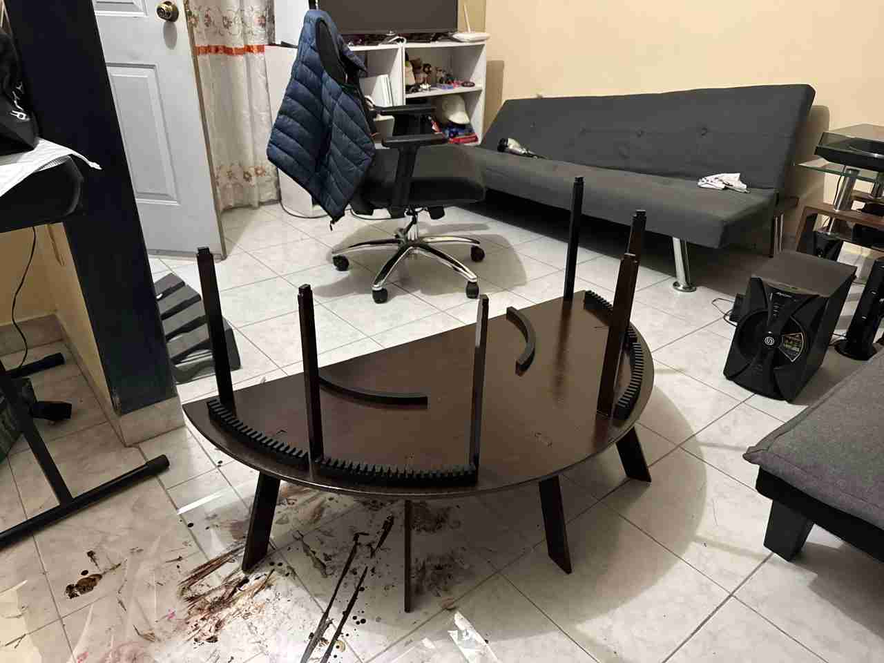
Assemble the top table with the other part of the table.
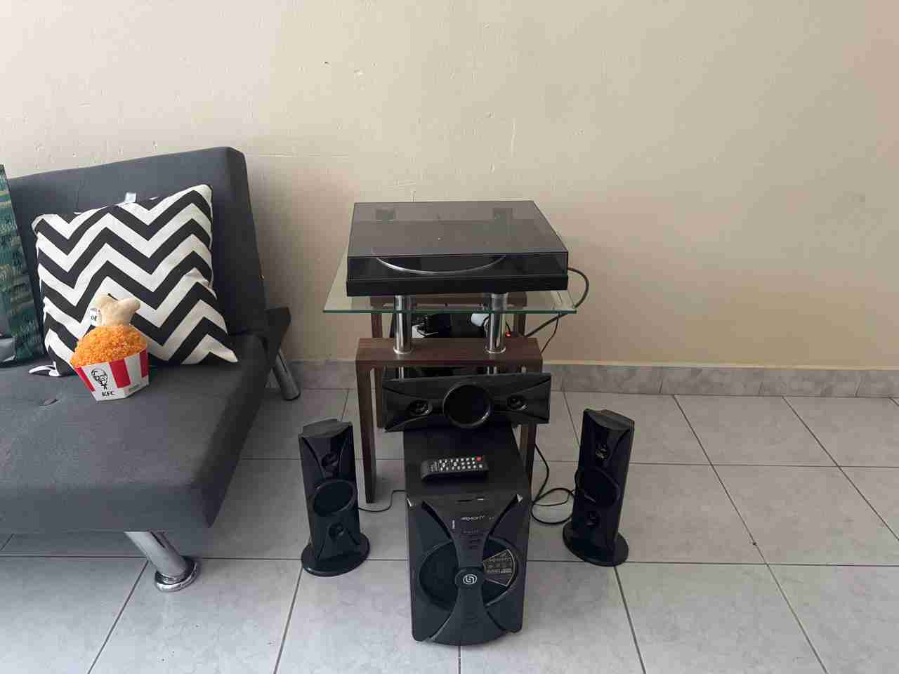
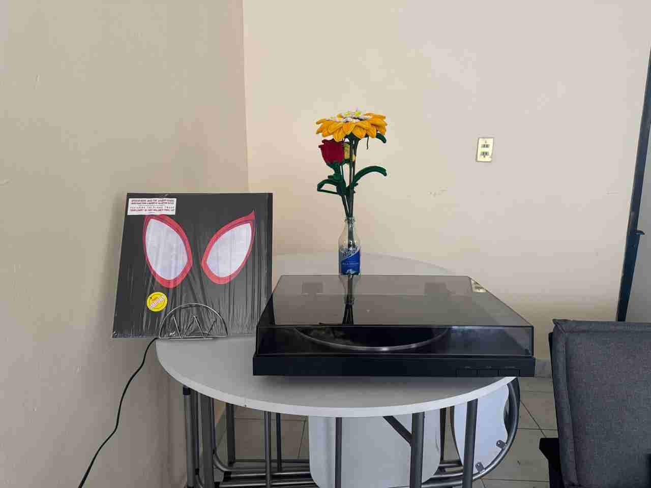
This is how my turntable table looks like with my vynils and my turntable.
5. Files created
Click on the "Download ZIP" to download all the files I made for this week assignment