NETWORKING AND COMMUNICATIONS
Individual assignments
- Design, build, and connect wired or wireless node(s) with network or bus addresses and local input &/or output device(s)
For this week, work was focused on communications and information exchange between devices. Knowing this, for this week it was decided to work with WiFi networks. Due to my major, I never had the opportunity to program or use microcontrollers that could be capable of using WiFi. Likewise, I decided to use this type of communication because I want to create a page where data collection and visualization can be observed. In the same way, I would love to integrate a system where I could control my robot remotely. Therefore, I consider that working with WiFi is my ideal option.
What is networking?
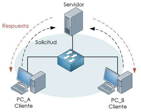
That is, networks. It is a connection process given through wiring systems or wireless technologies. The goal is the transfer of information from a point or node in the network. There are no intermediaries, because it is a direct path between connection points. A very simple example of its application is the use of a cellphone connected to WiFi to access the internet.
How Networking and Communications work
The connection between devices has different applications or functions, all depending on what is intended to be done. Among them, the following can be found:
- Location: it is known where a device is within the network.
- Parallelism: allows many devices to work at the same time.
- Modularity: allows separating data. For example, one sensor measures, another processes, and another sends data.
- Interference: allows avoiding signals from mixing or colliding.
For these to work, they need a device that generates the data, then this is converted into signals (electrical, radio, light), they travel through a medium, and another device receives and decodes the information. This is a general idea of how network communications work.
Types of communication
There are several types of communication (also that can be chosen for this week).
Wired
It refers to a type of communication with cables. The most typical is the serial type.
- Asynchronous (without clock): UART/USART type. There are no clock signals, instead they use an agreed speed. Usually, you can see this type of communication in Arduino when you set the speed of data collection in the Serial Monitor.
- Synchronous (with clock): There are several types. I2C type uses 2 cables (SDA referring to data and SCL with respect to the clock), this type of communication is a bit more complex and needs deeper study of the topic; On the other hand, there is SPI, which is much faster than I2C, it uses MOSI (data out), MISO (data in), SCK (clock), and CS (selection).
Wireless
That is, communications without cables. They are usually found in technologies such as: Wi-Fi (internet), Bluetooth, LoRa, etc.
This type of communication uses physical media to share information. It can be through wiring, using voltage or optical fiber. But it can also be wireless, such as radio frequency (in the case of Wi-Fi), light, sound.
What did I do in my week 11?
As I had already explained, during this week I worked with Wi-Fi HTTP. The way it works is by connecting the microcontroller being used to Wi-Fi and converting it into an HTTP web server. I relied on this page, which has very valuable information about networking.
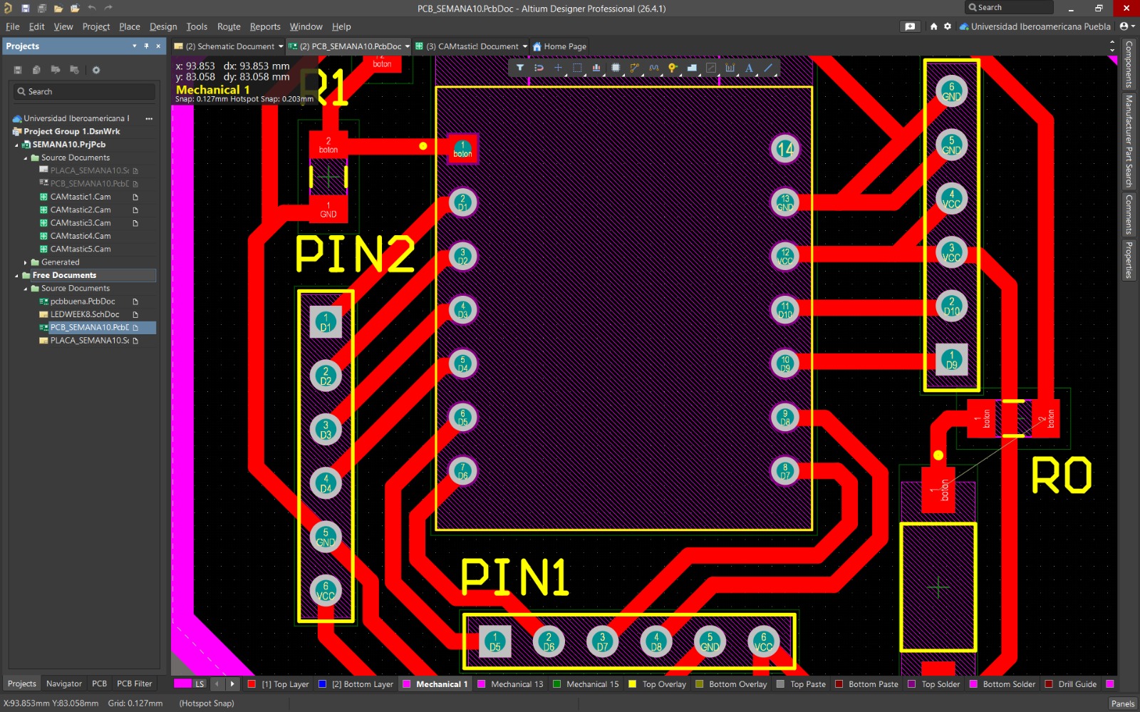
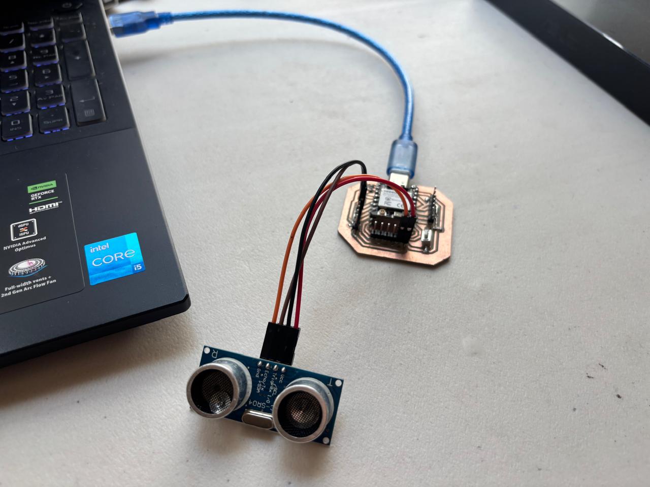
First, I designed a board in Altium using the XIAO ESP32C6 microcontroller. In this way, I relied on what was seen in week 6 and week 8. Afterwards, I did the following process.
1.Connection of the board to the computer
2. Open ARDUINO IDE
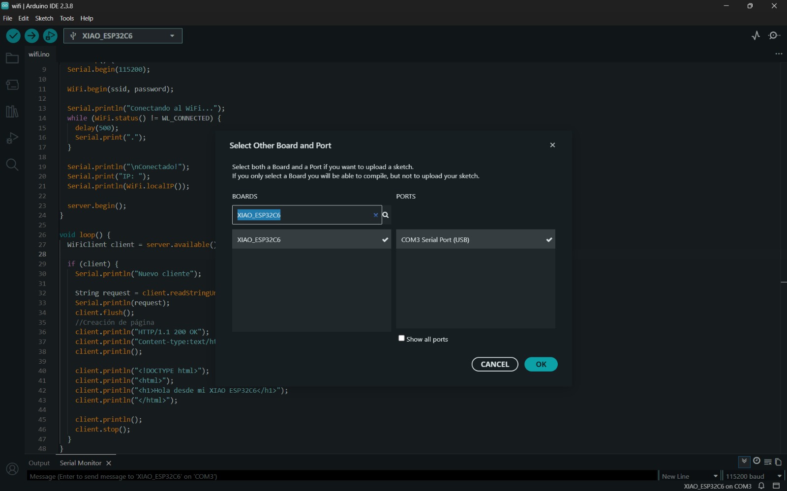
3.Modify, change, or select the type of board that is being used. In my case, a XIAO ESP32C6.
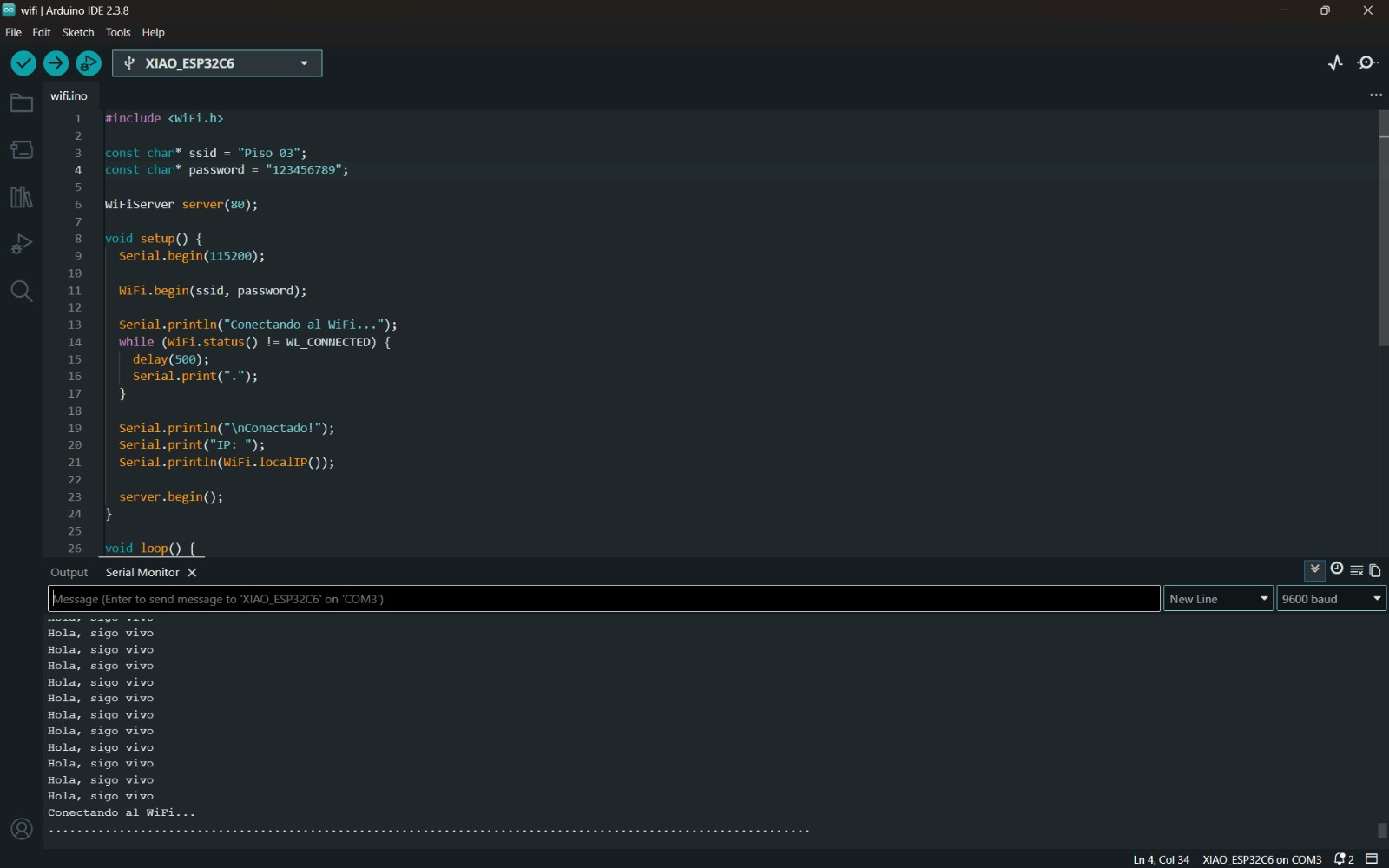
4. Test that the code can be uploaded to the board to confirm that everything is correctly connected.
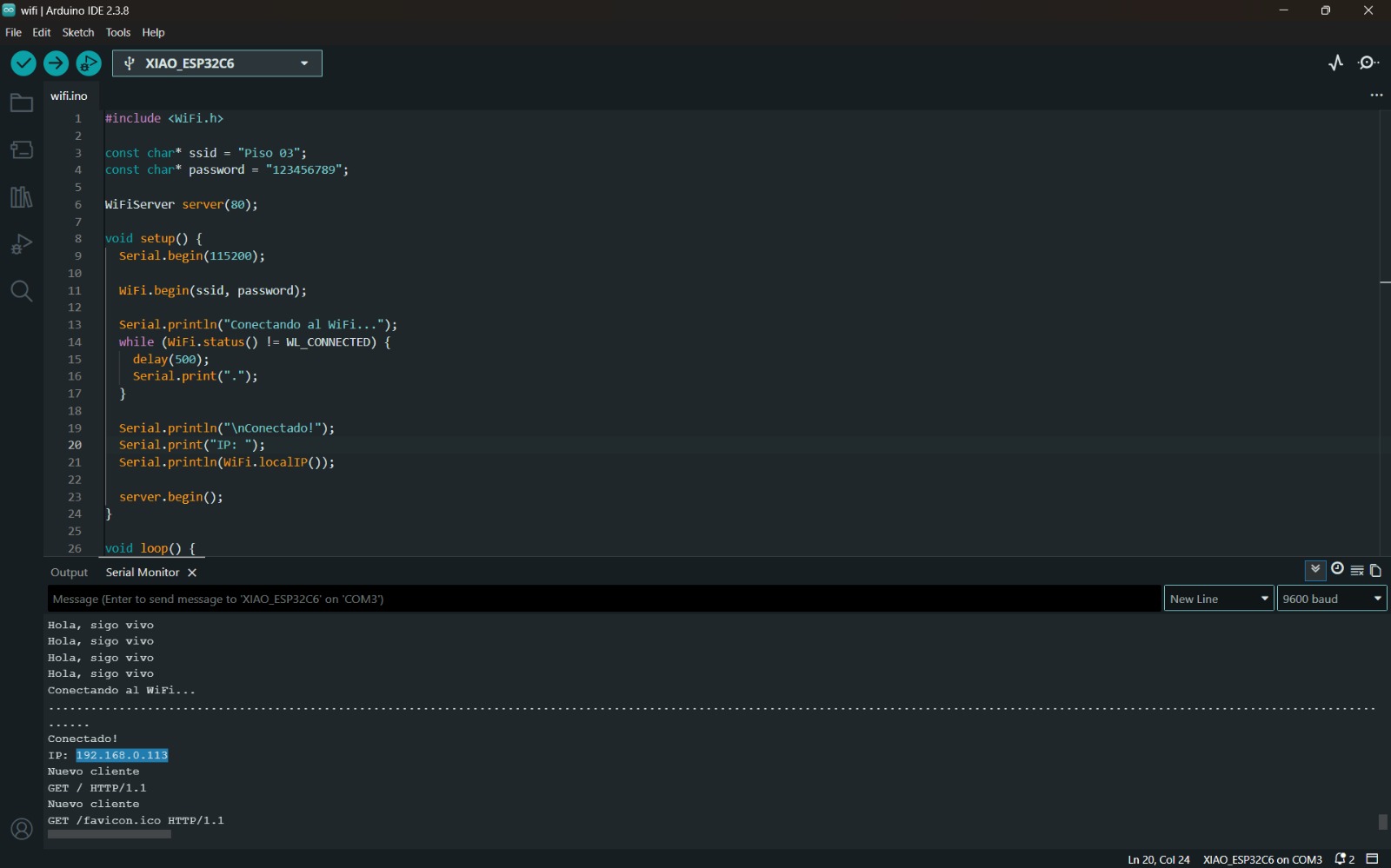
5. Perform programming code
#include <WiFi.h>

const char* ssid = "Piso 03";
const char* password = "123456789";

WiFiServer server(80);

void setup() {
  Serial.begin(115200);

  WiFi.begin(ssid, password);

  Serial.println("Conectando al WiFi...");
  while (WiFi.status() != WL_CONNECTED) {
    delay(500);
    Serial.print(".");
  }

  Serial.println("\nConectado!");
  Serial.print("IP: ");
  Serial.println(WiFi.localIP());

  server.begin();
}

void loop() {
  WiFiClient client = server.available();

  if (client) {
    Serial.println("Nuevo cliente");

    String request = client.readStringUntil('\r');
    Serial.println(request);
    client.flush();
    //Creación de página
    client.println("HTTP/1.1 200 OK");
    client.println("Content-type:text/html");
    client.println();

    client.println("<!DOCTYPE html>");
    client.println("<html>");
    client.println("<h1>Hola desde mi XIAO ESP32C6</h1>");
    client.println("</html>");

    client.println();
    client.stop();
  }
}
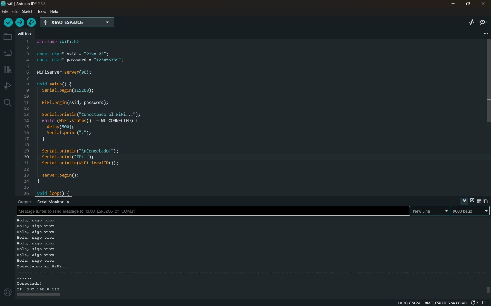
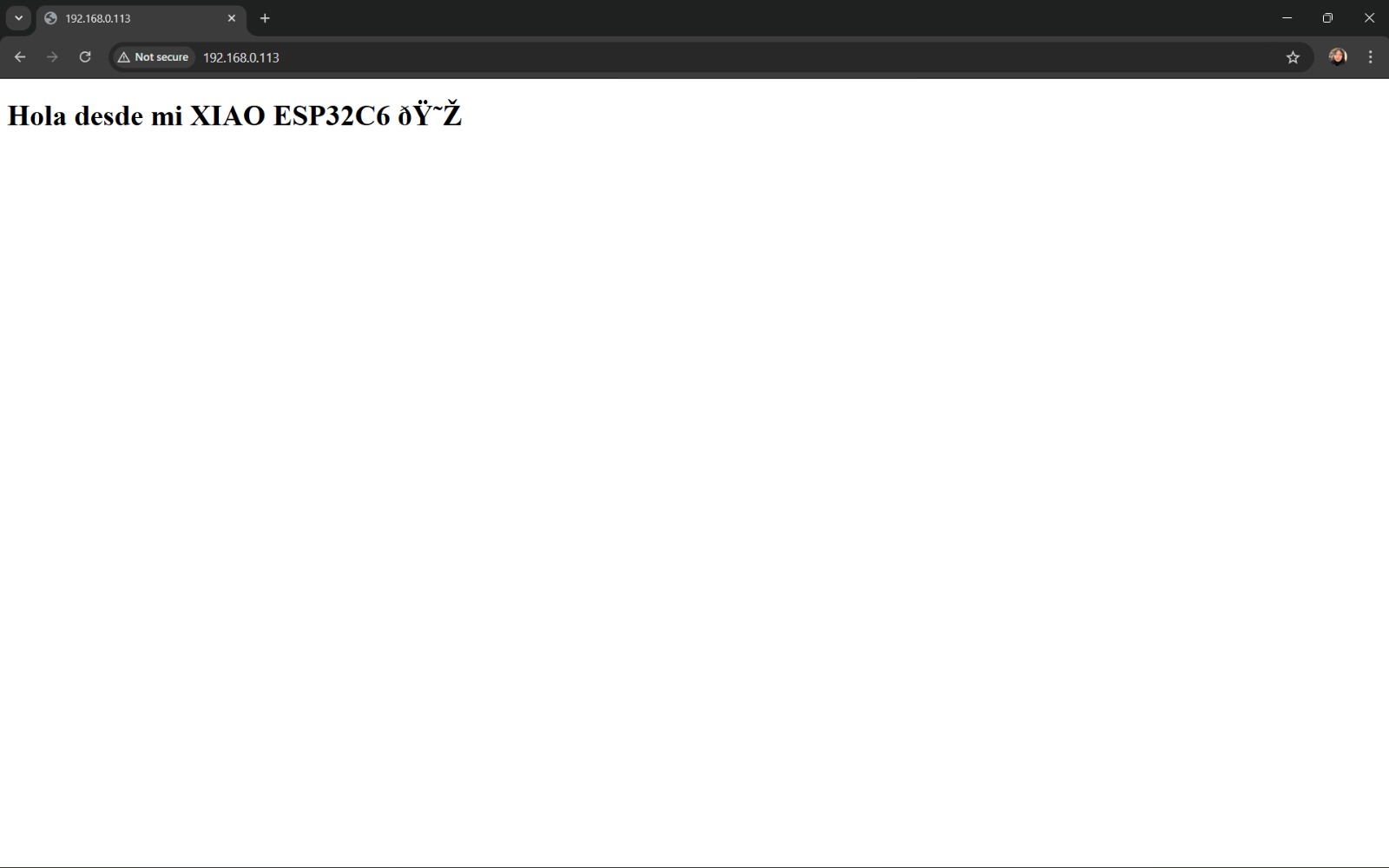
6. Once the program is uploaded to the microcontroller and it is tested that it works correctly, the IP given by the Serial Monitor was copied and pasted into a web browser. In this way, you can observe the created page.
7. Afterwards, you will be able to observe that there is a client or that this page has been visited.
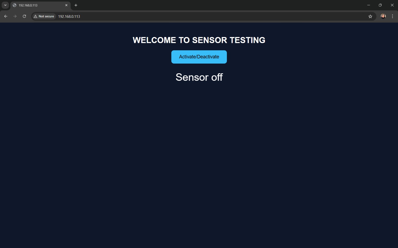
8. Finally, I modified some settings so that the page had a better presentation.
#include <WiFi.h> //Library that allows connecting my board to WiFi

//WiFi credentials are set here:
const char* ssid = "Piso 03"; //network name
const char* password = "123456789"; //network password

WiFiServer server(80); //Creates a web server on the standard port (HTTP), hence 80

//Sensor pin definitions
const int trigPin = D2; //sends pulse
const int echoPin = D1; //receives the bounce

bool sensorActive = false; //Allows knowing if the sensor is active or not

void setup() {
  Serial.begin(115200); //Allows viewing messages in the serial monitor

  //Configures the pins
  pinMode(trigPin, OUTPUT);
  pinMode(echoPin, INPUT);
  //WiFi connection - starts connection
  WiFi.begin(ssid, password);

  //Waits until connected and prints dots while waiting
  Serial.println("Connecting...");
  while (WiFi.status() != WL_CONNECTED) {
    delay(500);
    Serial.print(".");
  }
  //Prints or shows the IP in the Serial Monitor to access from browser
  Serial.println("\nConnected!");
  Serial.println(WiFi.localIP());
  //Starts web server
  server.begin();
}
//Function that allows measuring distance with the sensor
float measureDistance() {
  //Generates a pulse
  digitalWrite(trigPin, LOW);
  delayMicroseconds(2);

  digitalWrite(trigPin, HIGH);
  delayMicroseconds(10);
  digitalWrite(trigPin, LOW);
  //Measures the time it takes for the sound to return
  long duration = pulseIn(echoPin, HIGH);
  //Calculates the distance
  float distance = duration * 0.034 / 2;
  //Returns the distance in cm
  return distance;
}

void loop() {
  //Detect if someone connects to the browser
  WiFiClient client = server.available();
  //If there is a connection, read what the browser requested
  if (client) {
    String request = client.readStringUntil('\r');
    //Clears extra data
    client.flush();

    // If the button is pressed
    if (request.indexOf("/toggle") != -1) {
      //Change from OFF to ON or vice versa
      sensorActive = !sensorActive;

      client.println("HTTP/1.1 200 OK");
      client.println("Content-type:text/plain");
      client.println();
      client.println(sensorActive ? "ON" : "OFF");
      client.stop();
      return;
    }

    // Browser requests sensor data
    if (request.indexOf("/data") != -1) {
      client.println("HTTP/1.1 200 OK");
      client.println("Content-type:text/plain");
      client.println();
      //If active, measure distance or send
      if (sensorActive) {
        float distance = measureDistance();
        client.println(distance);
      } else {
        client.println("OFF");
      }

      client.stop();
      return;
    }

    // Web page
    client.println("HTTP/1.1 200 OK");
    client.println("Content-type:text/html");
    client.println();

    //Write HTML within the code without errors
    client.println(R"rawliteral(
<!DOCTYPE html>
<html>
<head>
<meta name="viewport" content="width=device-width, initial-scale=1">
<style>
body {
  font-family: Arial;
  text-align: center;
  background: #0f172a;
  color: white;
}
h1 {
  margin-top: 50px;
}
button {
  padding: 15px 30px;
  font-size: 18px;
  border: none;
  border-radius: 10px;
  background-color: #38bdf8;
  color: black;
  cursor: pointer;
}
button:hover {
  background-color: #0ea5e9;
}
#distance {
  font-size: 40px;
  margin-top: 30px;
}
</style>
</head>

<body>

<h1>WELCOME TO SENSOR TESTING</h1>

<button onclick="toggleSensor()">Activate/Deactivate</button>

<div id="distance">Sensor off</div>

<script>
function toggleSensor() {
  fetch('/toggle')
  .then(r => r.text())
  .then(d => {
    console.log("Status:", d);
  });
}

function update() {
  fetch('/data')
  .then(r => r.text())
  .then(d => {
    if(d === "OFF"){
      document.getElementById('distance').innerHTML = "Sensor off";
    } else {
      document.getElementById('distance').innerHTML = d + " cm";
    }
  });
}

setInterval(update, 1000);
</script>

</body>
</html>
)rawliteral");

    client.stop();
  }
}
9. This ended up being my final result.
Results
This code allows me to display in real time the data collected by my sensor. In this way, you can visualize the measured distances, as well as have control over turning the sensor on and off.
How does the programming work?
Based on the first code that was made, the logic it follows is:
- Board turns on.
- Connects to Wi-Fi.
- Outputs IP.
- The IP is copied and pasted into the browser.
- Send HTML.
- The page is displayed.
Regarding the libraries, the following are used:
Allows connection to the internet.
#include <WiFi.h>
Defines the network name and password.
          const char* ssid = "Piso 03";
          const char* password = "123456789";
Allows creating a web server. 80 is used because it is an HTTP port and it is the one used by browsers.
WiFiServer server(80);
Attempts to communicate or connect to Wi-Fi
WiFi.begin(ssid, password);
Waits for connection
while (WiFi.status() != WL_CONNECTED)
Prints the IP
Serial.println(WiFi.localIP());
Allows knowing if there are clients or not.
WiFiClient client = server.available();
Clears leftover data
client.flush();
This code establishes that it is a web page.
client.println("Content-type:text/html");
Finally, this code writes the normal web page.
          client.println("<!DOCTYPE html>");
          client.println("<html>");
          client.println("<h1>Hola desde mi XIAO ESP32C6</h1>");
          client.println("</html>");
This allows ending the communication.
client.stop();
UART Communication Type
Likewise, due to my project, it was important for me to implement another type of communication. This is UART, that is, Universal Asynchronous Receiver-Transmitter. It is a type of communication protocol that allows the exchange of information between two devices using two signal lines, TX and RX.
How does it work internally?
Unlike SPI or I2C communication, it does not use a shared clock between devices. Instead, both devices agree on a communication speed and use their own internal clocks to synchronize. It is the transmission of bytes between devices.
This type of communication can be programmed in:
- Arduino IDE: Serial, Serial1, Serial2, etc.
- MicroPython: using machine.UART()
- RaspberryPi Pico SDK: in C/C++
- PlatformIO
Among many others. This type of communication is one of the oldest; however, it still has many applications. It is very simple to use, since it only requires two data wires and one GND. It can be used with any microcontroller and does not require a master device.
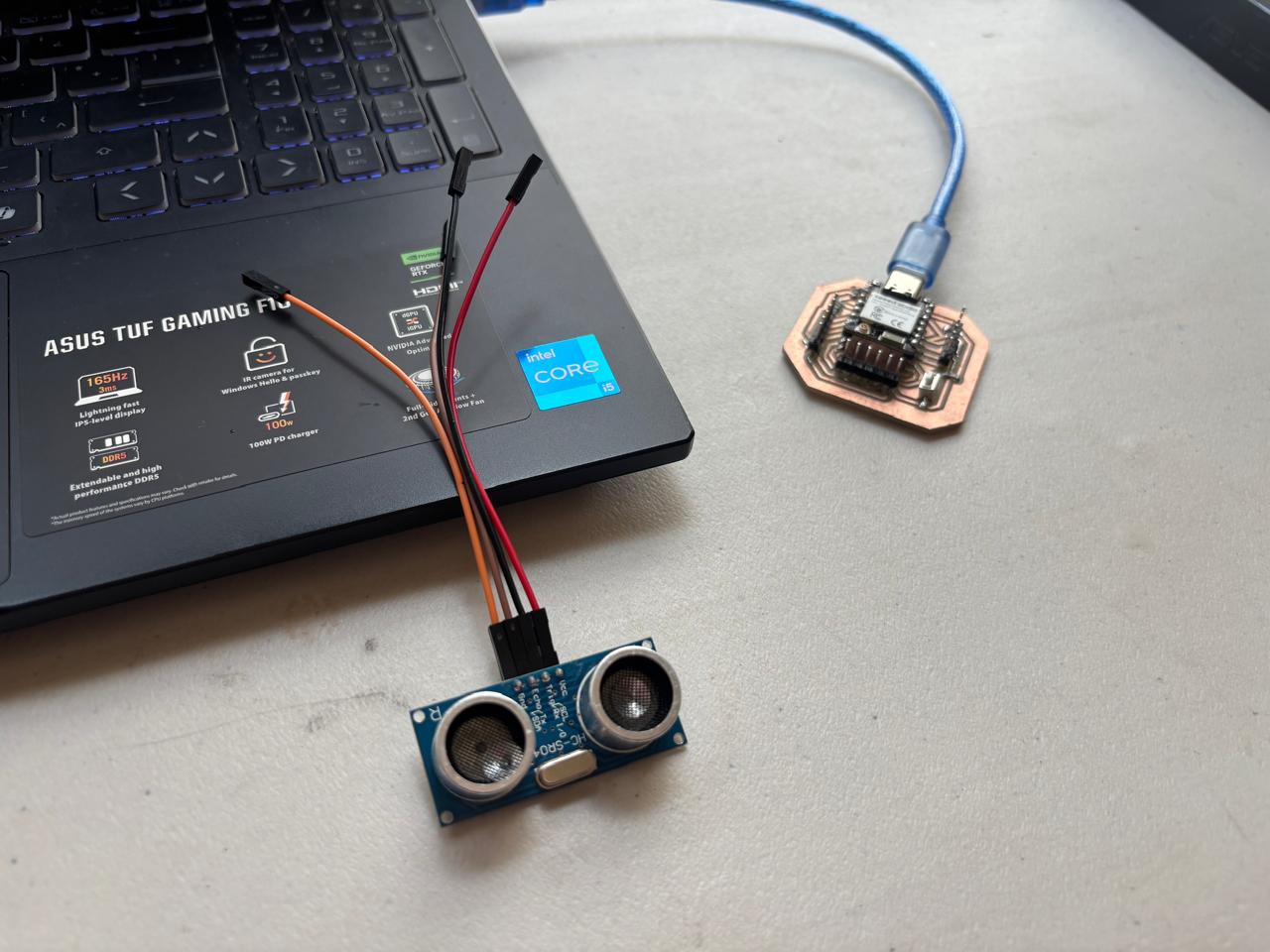
For my project, this type of communication will be widely used, since I will use two microcontrollers: one to receive data from the sensors I use and the other to move the motors according to that data. Based on this, I carried out a practice that demonstrates the use of this type of connection.
Practice
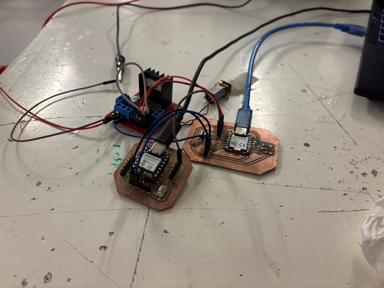
It consists of connecting two PCBs with XIAO ESP32C6 and XIAO RP2350 microcontrollers, each on its respective board. The connection was made using female-to-female wires, and code was developed in which, when my ESP32C6 received the button pulse, the motor connected to the RP2350 would move forward. To achieve this, two separate codes were used, corresponding to each board. These codes were uploaded to both boards, and specifically the XIAO ESP32C6 displayed real-time data about what was being performed.
In this way, I managed to obtain the following result:
This type of practice is very important, since it allowed me to learn about another type of communication that I will definitely use in my final project.This are the codes used:
Code for ESP32C6
#include

HardwareSerial SerialUART(1);

#define BOTON  D0

void setup() {
  Serial.begin(115200);
  SerialUART.begin(9600, SERIAL_8N1, D7, D6);
  pinMode(BOTON, INPUT_PULLUP);
  Serial.println("ESP32C6 listo");
}

void loop() {
  if (digitalRead(BOTON) == HIGH) {
    SerialUART.println("motor:ON");
    Serial.println("motor:ON");
  } else {
    SerialUART.println("motor:OFF");
    Serial.println("motor:OFF");
  }
  delay(50);
}
Code for RP2350
#define IN3  A2
#define IN4  A1

void setup() {
  Serial.begin(115200);
  Serial1.begin(9600);
  pinMode(IN3, OUTPUT);
  pinMode(IN4, OUTPUT);
  digitalWrite(IN3, LOW);
  digitalWrite(IN4, LOW);
  Serial.println("RP2350 listo");
}

void loop() {
  if (Serial1.available()) {
    String cmd = Serial1.readStringUntil('\n');
    cmd.trim();

    Serial.print("Comando recibido: ");
    Serial.println(cmd);

    if (cmd == "motor:ON") {
      digitalWrite(IN3, HIGH);
      digitalWrite(IN4, LOW);
      Serial.println("Motor girando...");
    } else if (cmd == "motor:OFF") {
      digitalWrite(IN3, LOW);
      digitalWrite(IN4, LOW);
      Serial.println("Motor detenido.");
    }
  }
}
Finally, these are some questions I had while working with this type of communication:
- Why are TX and RX crossed? This is because the TX pin is used to transmit information and RX to receive it. Therefore, if they are connected to the same type of pin, both devices would either be transmitting or receiving.
- Does anything happen if I use a different logic voltage? If two devices use different voltages, one higher than the other, it is likely that one of the lines could be damaged.
- Why is the same GND used? Due to the nature of UART communication, it is measured in voltages, so if there is no shared GND, there is a possibility of obtaining incorrect or inconsistent data.
I2C Communication
This type of communication is called Inter-Integrated Circuit. It is a type of communication that allows two devices to communicate with each other using the smallest number of wires possible. In general, it can be observed that:
Where all connected devices share the same two wires, which are called a bus.
What is an I2C address?
The devices sharing the same bus need a way to identify themselves. Each device has a 7-bit address, giving 128 possible addresses ranging from 0x00 to 0x7F. The addresses are written in hexadecimal.
Therefore, for this type of communication, there are two roles: Master (starts the communication) and Slave (waits to be addressed). It is necessary to consider that, for this type of communication to work, pull-up resistors must be used, since I2C devices use a logic called open-drain. This type of communication is ideal for multiple sensors and few pins.
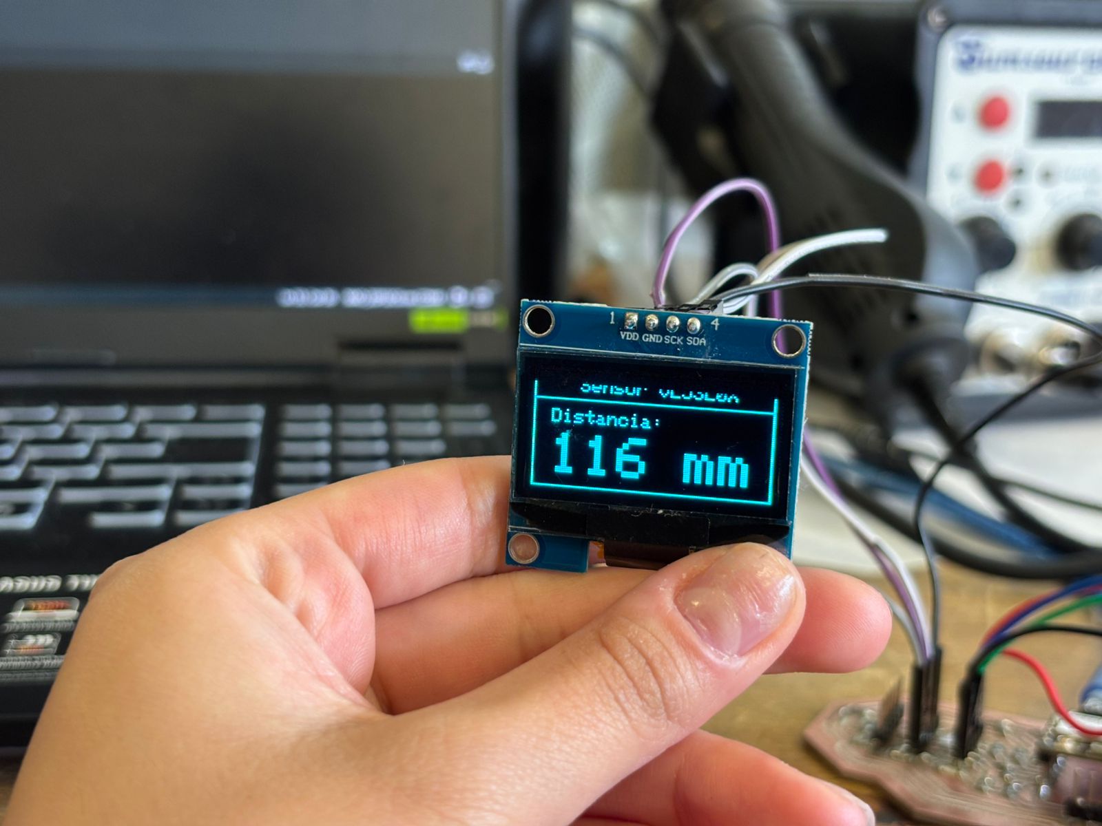
For this practice, a XIAO ESP32C6 (using the board designed for the final project) will be connected with an OLED SH1106 display and a VL53L0X distance sensor to measure distances. Finally, the code used is the following:
#include
#include
#include
#include
#include

#define i2c_Address 0x3C
#define SCREEN_WIDTH 128
#define SCREEN_HEIGHT 64
#define OLED_RESET -1
#define XSHUT_PIN D0

Adafruit_SH1106G display = Adafruit_SH1106G(SCREEN_WIDTH, SCREEN_HEIGHT, &Wire, OLED_RESET);
Adafruit_VL53L0X sensor = Adafruit_VL53L0X();

void setup() {
  Serial.begin(115200);
  delay(200);

  // Turn on sensor
  pinMode(XSHUT_PIN, OUTPUT);
  digitalWrite(XSHUT_PIN, HIGH);
  delay(10);

  Wire.begin(D4, D5);

  // Start display
  if (!display.begin(i2c_Address, true)) {
    Serial.println("OLED not found");
    for(;;);
  }

  // Start sensor
  if (!sensor.begin()) {
    Serial.println("VL53L0X not found");  // In case something does not work
    display.clearDisplay();
    display.setTextSize(1);
    display.setTextColor(SH110X_WHITE);
    display.setCursor(0, 25);
    display.println("Error: I2C sensor");
    display.display();
    for(;;);
  }

  // Startup screen
  display.clearDisplay();
  display.drawRect(0, 0, SCREEN_WIDTH, SCREEN_HEIGHT, SH110X_WHITE);
  display.setTextSize(1);
  display.setTextColor(SH110X_WHITE);
  display.setCursor(20, 10);
  display.println("XIAO ESP32C6");
  display.setCursor(20, 22);
  display.println("I2C bus ready");
  display.setCursor(10, 34);
  display.println("OLED  |  VL53L0X");
  display.setCursor(10, 46);
  display.println("Welcome");
  display.display();
  delay(2000);
}

void loop() {
  VL53L0X_RangingMeasurementData_t medicion;
  sensor.rangingTest(&medicion, false);

  display.clearDisplay();
  display.drawRect(0, 0, SCREEN_WIDTH, SCREEN_HEIGHT, SH110X_WHITE);

  display.setTextSize(1);
  display.setTextColor(SH110X_WHITE);
  display.setCursor(25, 5);
  display.println("VL53L0X Sensor");
  display.drawLine(0, 16, 127, 16, SH110X_WHITE);

  if (medicion.RangeStatus != 4) {
    int distancia = medicion.RangeMilliMeter;

    Serial.print("Distance: ");
    Serial.print(distancia);
    Serial.println(" mm");

    display.setCursor(10, 22);
    display.setTextSize(1);
    display.println("Distance:");
    display.setTextSize(3);
    display.setCursor(10, 35);
    display.print(distancia);
    display.print(" mm");

  } else {
    Serial.println("Out of range");
    display.setTextSize(1);
    display.setCursor(15, 30);
    display.println("Out of range");
  }

  display.display();
  delay(200);
}
This code uses the libraries to manage I2C communication, the basic graphics, the display controller, and the sensor (defined with #include). Likewise, the I2C addresses of the display, the screen width and height, the pin responsible for turning the sensor on or off, and the setting that the display does not have a reset pin are defined (using #define). From there, the objects used for communication are created and the programs are executed.
From this, it is possible for two different devices that share the same wires to communicate without confusion because each one has its own address. The final result is the following:
ESP-NOW
Now, in order to connect two ESP32C6 boards, I used ESP-NOW. This protocol works as a direct messaging system between boards, where the transmitter needs to know the destination device to which the data will be sent. This identifier is known as the MAC address. To obtain it, the following code is first uploaded:
#include
#include

void setup() {
  Serial.begin(115200);
  WiFi.mode(WIFI_STA);
  Serial.print("MAC del receptor: ");
  Serial.println(WiFi.macAddress());
}

void loop() {}
Once this is done, the board outputs its MAC address through the serial monitor. This address is then copied into the transmitter board. These values correspond to the MAC address bytes.
The transmitter code defines the data structure that will be sent. It is important that the receiver uses the exact same data structure to correctly interpret the incoming information. Additionally, the transmitter initializes the VL53L0X sensor, starts ESP-NOW communication, and repeatedly sends the collected data. The code is shown below:
#include
#include
#include
#include
#include "VL53L0X.h"


#define XSHUT_PIN  D2
#define SDA_PIN    D4
#define SCL_PIN    D5


uint8_t MAC_Receptor[] = {0xFF, 0xFF, 0xFF, 0xFF, 0xFF, 0xFF}; // REEMPLAZA_CON_TU_MAC


typedef struct Mensaje {
  uint16_t distancia_mm;
} Mensaje;

Mensaje datos;

TwoWire I2C_sensor = TwoWire(0);
VL53L0X sensor;

void onDataSent(const wifi_tx_info_t* info, esp_now_send_status_t status) {

}

void setup() {
  Serial.begin(115200);

  // Inicializar VL53L0X
  pinMode(XSHUT_PIN, OUTPUT);
  digitalWrite(XSHUT_PIN, LOW);
  delay(10);
  digitalWrite(XSHUT_PIN, HIGH);
  delay(10);

  I2C_sensor.begin(SDA_PIN, SCL_PIN);
  sensor.setBus(&I2C_sensor);
  if (!sensor.init()) {
    Serial.println("ERROR: VL53L0X no encontrado");
    while (1);
  }
  sensor.setTimeout(500);
  sensor.startContinuous();
  Serial.println("VL53L0X listo");

  // Inicializar ESP-NOW
  WiFi.mode(WIFI_STA);
  if (esp_now_init() != ESP_OK) {
    Serial.println("ERROR: ESP-NOW no inició");
    while (1);
  }
  esp_now_register_send_cb(onDataSent);

  esp_now_peer_info_t peer = {};
  memcpy(peer.peer_addr, MAC_Receptor, 6);
  peer.channel = 0;
  peer.encrypt = false;
  if (esp_now_add_peer(&peer) != ESP_OK) {
    Serial.println("ERROR: No se pudo agregar el receptor");
    while (1);
  }

  Serial.println("Transmisor listo");
}

void loop() {
  uint16_t lectura = sensor.readRangeContinuousMillimeters();
  if (!sensor.timeoutOccurred()) {
    datos.distancia_mm = lectura;
    esp_now_send(MAC_Receptor, (uint8_t *)&datos, sizeof(datos));
    Serial.print("Enviado: ");
    Serial.print(datos.distancia_mm);
    Serial.println(" mm");
  }
  delay(50);
}
While the receiver code listens for and accepts messages from any address. The system is designed so that a callback function is automatically executed whenever new data is received. The received information is then extracted and converted into the previously defined data structure. The corresponding code is shown below:
#include
#include
#include


typedef struct Mensaje {
  uint16_t distancia_mm;
} Mensaje;

Mensaje datos;

void onDataReceived(const esp_now_recv_info_t* info, const uint8_t* data, int len) {
  memcpy(&datos, data, sizeof(datos));
  Serial.print("Distancia recibida: ");
  Serial.print(datos.distancia_mm);
  Serial.println(" mm");
}

void setup() {
  Serial.begin(115200);
  WiFi.mode(WIFI_STA);

  Serial.print("MAC de este receptor: ");
  Serial.println(WiFi.macAddress());

  if (esp_now_init() != ESP_OK) {
    Serial.println("ERROR: ESP-NOW no inició");
    while (1);
  }
  esp_now_register_recv_cb(onDataReceived);

  Serial.println("Receptor listo");
}

void loop() {
  delay(10);
}
Finally, the obtained results are:
Conclusions
It is important to understand connections and how they work so that communication between devices can be established to control systems remotely, view data in real time, exchange information, and automation. During this week, it was achieved that the XIAO ESP32C6 board acted as a server capable of interacting with a user through a web page.
If you want to access to my work from this week, please click here to download!
Finally, for the group assignment for this week, you can find the information here