OUTPUT DEVICES
Individual assignments
- Add an output device to a microcontroller board you've designed, and program it to do something
This week is about output devices. During this week, I reused the PCB board made in week 8.
What are output devices?
They are hardware components that take electrical signals, decisions, or data from a microcontroller and convert them into something physical or observable in the real world. These can be seen as movement generated by electrical signals, light and indicators, displays, sound, etc.
The way I understood the meaning of an output device is to see it as the processor bringing decisions into the real world. There are different types of output devices, such as:
- Lights (LEDs, incandescent bulbs)
- Displays (LCD, OLED)
- Speakers
- Actuators (motors, solenoids)
Based on my final project, I wanted to carry out a movement practice. From this, I decided to use Pololu motors. These are high-precision and high-quality DC gear motors. They are commonly used in robotics and are small.
Idea for the week’s practice
For this week, I wanted to use two Pololu motors. I consider this choice a good practice, since it allows me to become familiar with DC motors (which I will use). To do this, I first learned the operating logic of this type of motor, as well as essential components I needed to use.
First, I considered the voltage at which my microcontroller operates (3.3V) and that of the Pololu motor (6V). Since I cannot connect them directly to my XIAO, I used an L298N driver, which allowed separation.
L298N Driver
This is a motor driver module that allows controlling the speed and direction of two DC motors. These are designed to support voltages from 5V to 35V. This type of driver is characterized by integrating H-bridges. Particularly, this driver has a dual H-bridge, which allows reversing the direction of motor rotation and controlling speed.
What is an H-bridge?
It is an electronic circuit that allows DC motors to rotate in both directions. These are fundamental in robotics for controlling DC motors, power inverters, or automation.
At the same time, the L298N driver is universal and usually can work with any type of microcontroller. The control pins (IN1, IN2, IN3, IN4) can recognize any signal greater than 2.3V as a High state.
Regarding the design of the L298N module, it can be seen as two separate electrical paths inside:
- Power path: where the voltage or power supply enters and goes directly to the motors. Path 1: Controls Motor 1
- Control path: where the IN1, IN2, IN3, and IN4 pins are located. These are responsible for receiving voltage from the microcontroller to turn on or off.
One of my main concerns was that nothing would burn (my microcontroller), so the driver was perfect to drive the motors without anything burning, since its design does not pass voltage to the microcontroller.
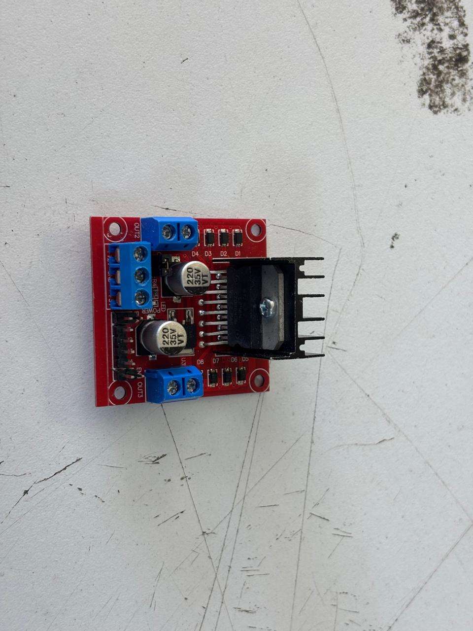
How to know how to use the L298N driver?
The driver is composed of these essential parts where the cables are connected to the microcontroller. On the left side of the image, two blue blocks called OUT1 and OUT2 can be seen. These are where the motor wires are connected, you simply loosen the screw to place the wire inside the block and tighten it once placed. On the right side, the same blocks can be seen, used to connect the second motor. Meanwhile, the three blue blocks indicate from left to right: input voltage (where the motors are powered), GND (shared ground with the PCB and the negative side of the power supply), and 5V output (nothing was connected here).
Finally, there are the input pins, where the XIAO is connected. On the sides of these are pins that activate the motors; the left side is for activating the left motor. An easier way that helps me organize and know how to connect it is through tables:
| On L298N driver | How to connect? |
|---|---|
| Left and right blocks. | Motor wires. Do not worry too much about how to connect them; each wire goes into its respective block. If you connect them backwards, you will notice through programming. |
| Lower left blue block. | Connects directly to the positive power supply. |
| Lower middle blue block. | Two wires are connected: GND to PCB ground and the other wire to the negative power supply. It is important to create a common ground so that voltages are set to 0V. |
| Lower right blue block. | I did not connect it to anything. |
| Pins IN1, IN2, IN3, and IN4. | Connected directly to pins D0 to D4 of the XIAO. |
| Pins ENA and ENB | These pins were bridged. I used a female-to-female cable and connected the ENA pins together. The same for ENB. |
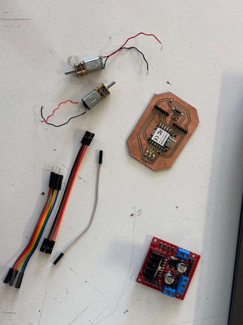
Materials used
- PCB board fabricated in week 10
- L298N driver
- 2 male-to-male wires
- 1 male-to-female wire
- 6 female-to-female wires
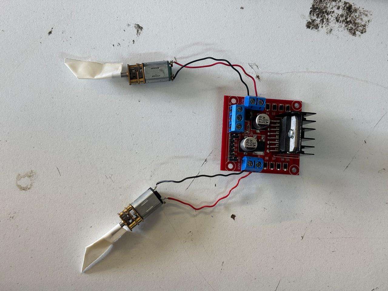
How to connect the motors
In this video, my process of connecting the motors to the driver can be shown. For this, I only loosened the screws so I could place the motor wires under them and in their respective block. Once placed, I tightened them again so they would be secure. This is how the connection is made.
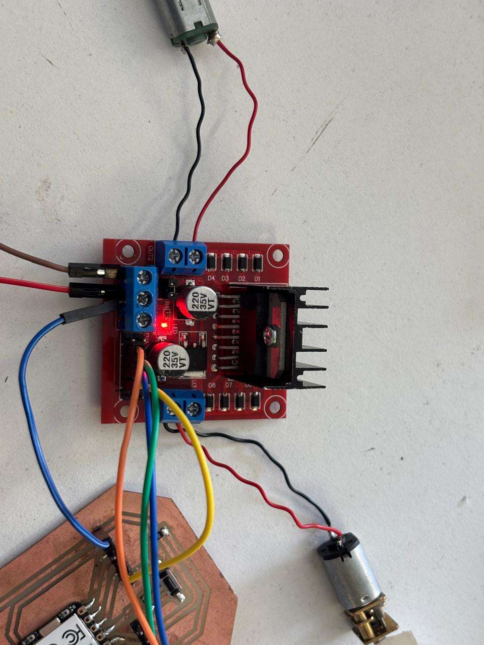
How to connect Driver to PCB
In the following video, it can be observed how I connected the driver pins to the PCB. This was done with female-to-female wires. Likewise, I connected the ENB and ENA pins. Finally, I connected the driver GND to the PCB with a male-to-female cable.
How I used a power supply
Since it was my first time using a power supply, the one available at the university is the following:
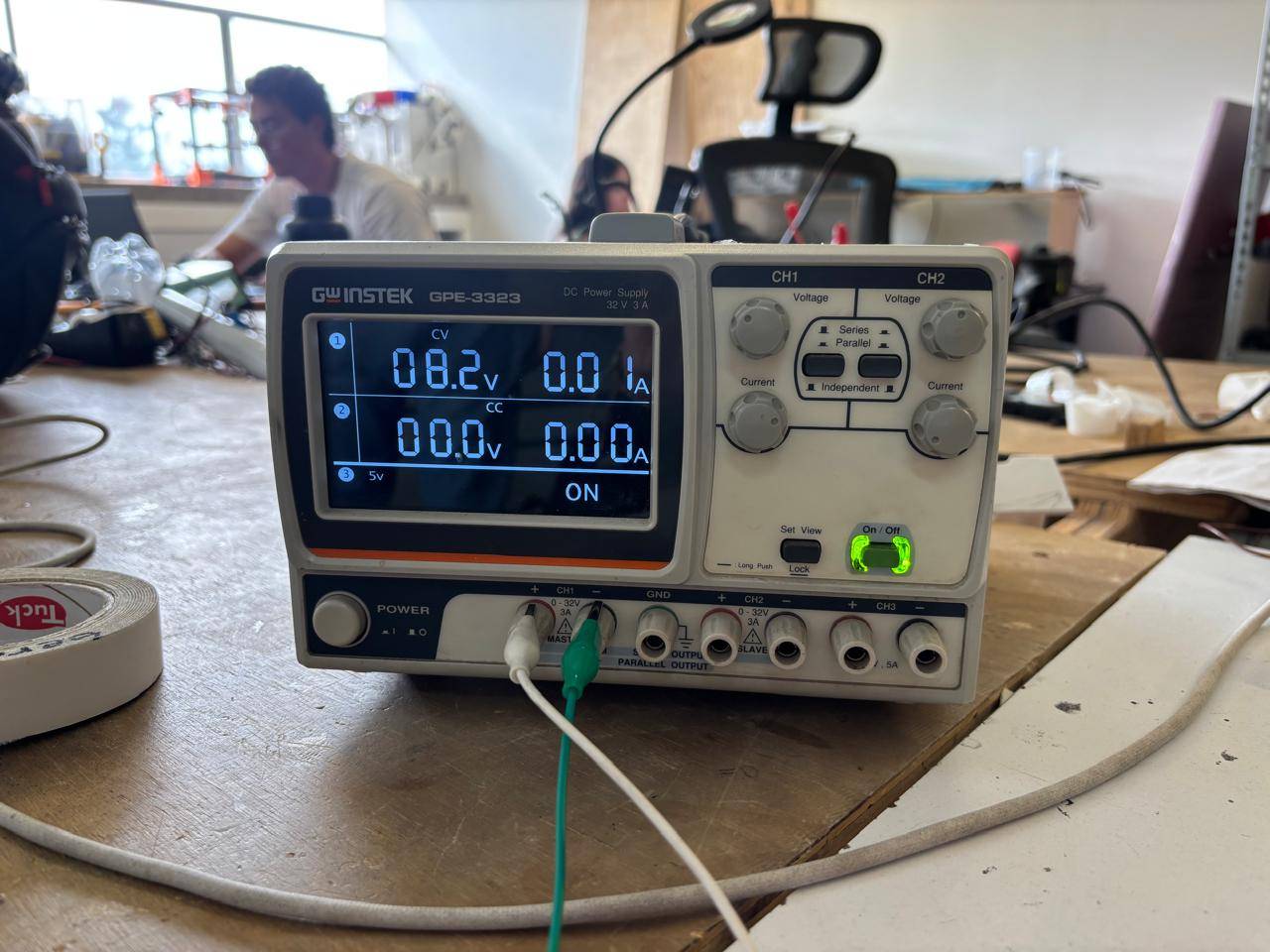
First, it is turned on by pressing the button labeled Power. Then, to change the voltage, I turned the knob. In my case, I adjusted the CH1 knob until I could observe the desired voltage level. Finally, I pressed the On/Off button so that current flows through the cables connected at the bottom in CH1.
Power calculation
Electrical power is the total amount of energy that the circuit is consuming at a given moment to be able to move. It is measured in Watts (W). To calculate it, Watt’s law is used, where the force with which electricity is pushed (voltage) is multiplied by the amount of electricity that is flowing (current), that is: P = V × I.
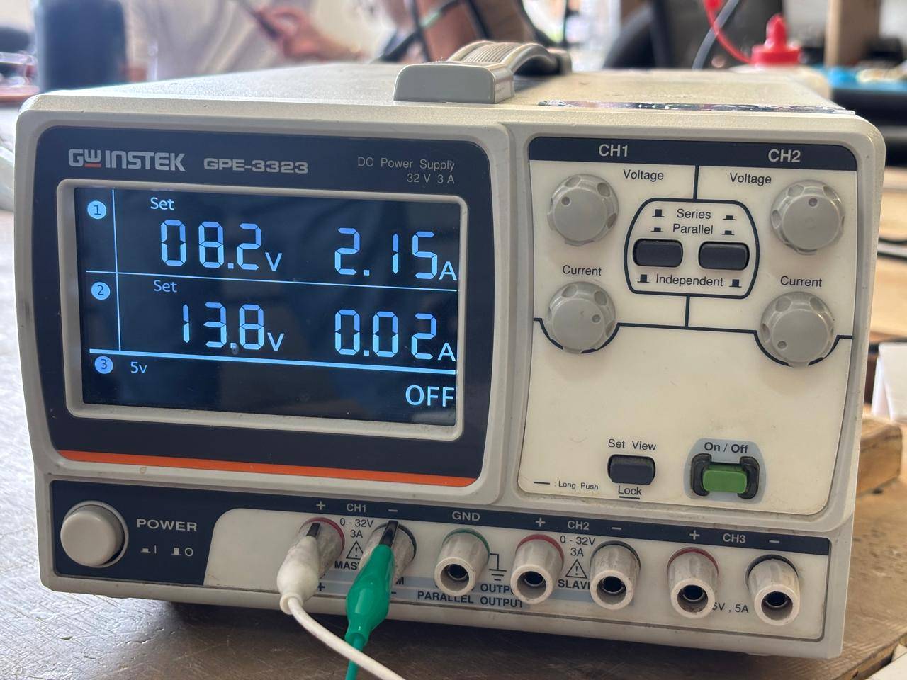
Since I needed 8V to power my circuit, the supply indicates the current. In my case, I used 8.2V and had a current of 0.04, so my power is 0.328W.
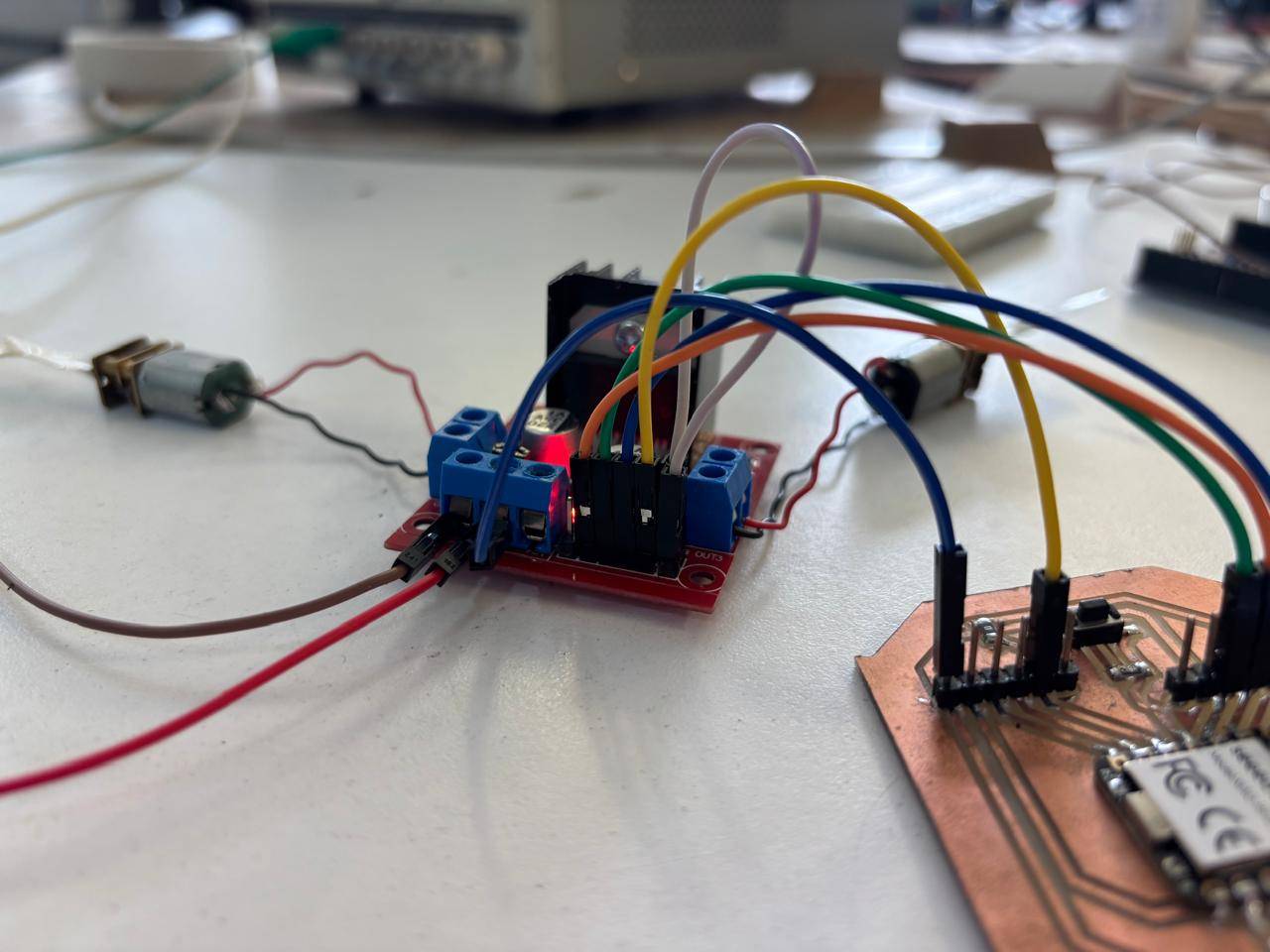
How everything was connected at the end
In this way, I was able to obtain this circuit:
Programming in ARDUINO IDE
To program the motors, I used ARDUINO IDE. It was not necessary to download any extra library to control the motors. The code I developed consists of:
Defining the XIAO pins connected to the driver. Then, I configure the pins as voltage outputs. The motor is stopped for safety, and I give a short pause before starting to move them. The program is designed so that the motors move forward, stop, move backward, and then stop again. This is the code I used:
// 1. Definimos los pines del XIAO conectados al L298N
const int IN1 = D1; // Control Motor Izquierdo (A)
const int IN2 = D2; // Control Motor Izquierdo (A)
const int IN3 = D0; // Control Motor Derecho (B)
const int IN4 = D4; // Control Motor Derecho (B)

void setup() {
  // 2. Configuración de todos los pines como SALIDAS de voltaje
  pinMode(IN1, OUTPUT);
  pinMode(IN2, OUTPUT);
  pinMode(IN3, OUTPUT);
  pinMode(IN4, OUTPUT);

  //motores inician apagados
  detener();

  // Pequeña pausa de 2s
  delay(2000);
}

void loop() {
  // 3. Pruebas: Adelante, Alto, Atrás, Alto.

  adelante();         // Llama a la función para avanzar
  delay(2000);        // Mantiene esa acción por 2 segundos

  detener();          // Llama a la función para frenar
  delay(1000);        // Se queda quieto 1 segundo

  atras();            // Llama a la función para retroceder
  delay(2000);        // Mantiene esa acción por 2 segundos

  detener();          // Frena
  delay(3000);        // Espera 3 segundos antes de repetir todo el ciclo
}

// ==========================================
// FUNCIONES DE MOVIMIENTO
// ==========================================

void adelante() {
  // Motor Izquierdo hacia adelante
  digitalWrite(IN1, HIGH);
  digitalWrite(IN2, LOW);

  // Motor Derecho hacia adelante
  digitalWrite(IN3, HIGH);
  digitalWrite(IN4, LOW);
}

void atras() {
  // Motor Izquierdo hacia atrás (invertir los HIGH y LOW)
  digitalWrite(IN1, LOW);
  digitalWrite(IN2, HIGH);

  // Motor Derecho hacia atrás
  digitalWrite(IN3, LOW);
  digitalWrite(IN4, HIGH);
}

void detener() {
  // Se apagan todas las señales para que los motores se detengan
  digitalWrite(IN1, LOW);
  digitalWrite(IN2, LOW);
  digitalWrite(IN3, LOW);
  digitalWrite(IN4, LOW);
}
Result
After connecting everything correctly and supplying the necessary voltage, I obtained the following results.
Conclusions
This week was very enriching. One of my constant fears is burning something; however, I think that if you learn things well from a theoretical basis, it is difficult for something to go wrong in practice, unless you make a mistake. I was able to learn how H-bridges work, how drivers function, and how to connect motors in such a way that they can be controlled with the previously fabricated PCB. It is important to consider the voltage used by the motors, the microcontroller, and to know how to connect everything correctly.
If you want to access to my work from this week, please click here to download!
Finally, for the group assignment for this week, you can find the information here