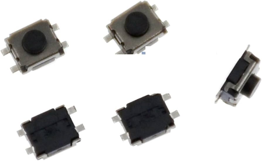
Mechanical devices
Such as buttons, switches, toggles, etc. These detect physical contact and their signal type is digital.
During this week, we will look at input devices, that is to say, the devices or components that send information to the microcontroller. It can be understood more simply if we think of it as a system that tells what is happening on the outside. For me, one of the fundamental things that must always be considered is understanding the theory and then applying it. Both are activities that allow complementing information for future work.
They are physical devices that generate information for the system. These are mediums or tools.
This week it is also expected to understand the data input mechanism to the microcontroller.
For this, the following are needed: Input Ports, where the sensor is connected and is the physical input. Subsequently, a Comparator, where it is decided if a signal exceeds a threshold, meaning, it converts simple analog to digital. Then, A/D allows converting the analog signal into a digital number, as it allows reading analog sensors. Finally, I2C brings that digital data from the sensor, meaning, it communicates.
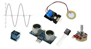
There are different types of input devices, as it is any element that detects something and converts it into a signal, whether analog or digital.
Analog signals are signals that can take any value within a range, they are continuous, change smoothly, and represent the real world. Example: temperature, sound, etc. While digital signals only have discrete values, normally 0 or 1. These do not have intermediate values and are easier to process. Example: buttons, motion sensors.
Input devices are the data source while the microcontroller is the one that processes the data. Some input devices are:
Such as buttons, switches, toggles, etc. These detect physical contact and their signal type is digital.
They are temperature sensors like the LM35, light sensors, potentiometers, etc. These measure continuous physical magnitudes and their signals are analog.
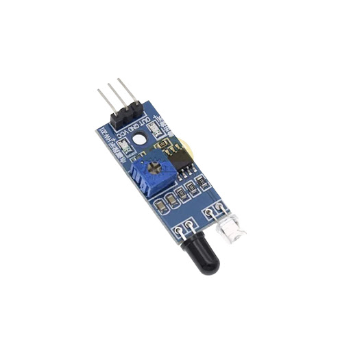
Such as ultrasonic sensors, motion sensors, infrared sensors. They allow detecting events or generating pulses and are digital signals.
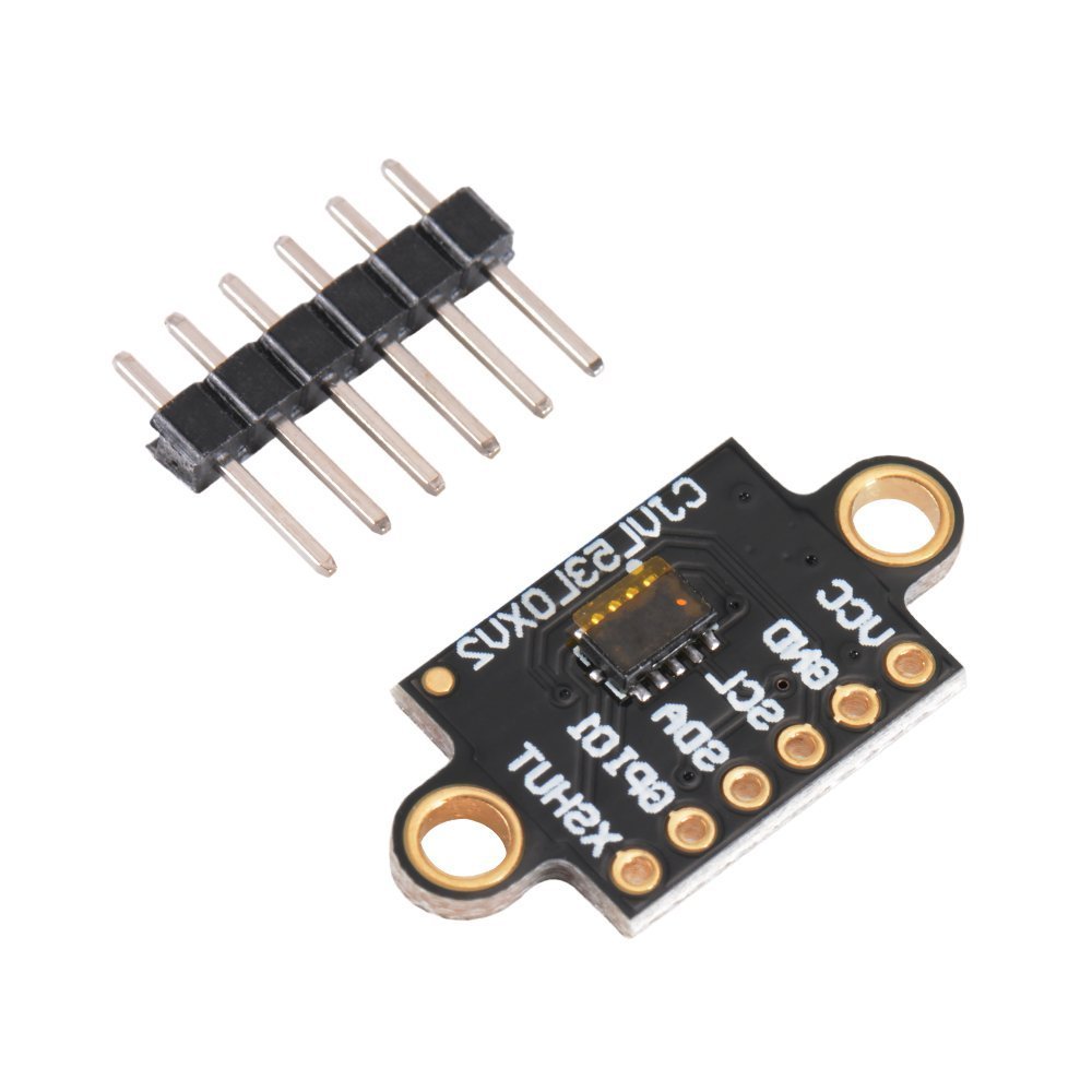
Sensors like VL53L0X, MPU6050, etc. They measure complex variables. And their signal types are digital I2C, SPI.
Regarding microcontroller modules, which are those that process or interpret signals, we have:
Regarding interfaces or communication methods, that is, those that transport data, we have:
Based on the above, for this week our main task will be to use a sensor on the manufactured board and obtain values or measurements generated by this sensor. To do this, it is important to consider various aspects so that the process turns out as efficiently and accurately as possible. For this, I focused on the following aspects.
For this, I was given a list of different types of inputs that I could use. It is important to know them and know how they work to subsequently select the type of sensor that will be worked with.
First of all, I considered the board I manufactured, you can find my process at this link. It has a XIAO RP2350 microcontroller, which works with 3.3V. Likewise, based on the PCB schematic I made in the Altium design program, I guided myself to know which pins I should connect the sensor to. To do this, recalling the pins that my PCB contains:
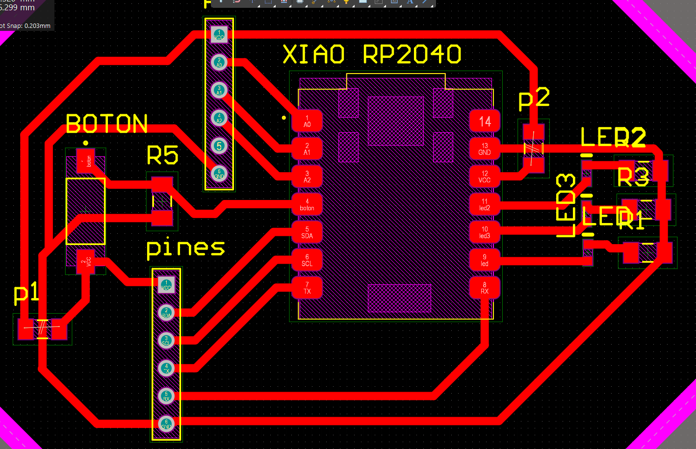
From this guide, it was easier for me to know how to take advantage of the pins I have on my PCB.
| Pinout | Pin type |
|---|---|
| A0-GPIO26-D0 | Digital/Analog/GPIO |
| A1-GPIO27-D1 | Digital/Analog/GPIO |
| A2-GPIO28-D2 | Digital/Analog/GPIO |
| SPI0_CSn-GPIO5-D3 | Digital/SPI/GPIO |
| SDA1-GPIO6-D4 | IIC/GPIO/Digital |
| SCL1-GPIO7-D5 | IIC/GPIO/Digital |
| TX0-GPIO0-D6 | UART/GPIO/Digital |
| 5V | Power |
| GND | GND |
| 3V3 | Power |
| D10-GPIO3-SPI0_MOSI | Digital/SPI/GPIO |
| D9-GPIO4-SPI0_MISO | Digital/SPI/GPIO |
| D8-GPIO2-SPI0_SCK | Digital/SPI/GPIO |
| D7-GPIO1-RX0 | Digital/GPIO/UART |
For me, it was extremely important to consider the type of pins that exist. It is necessary to highlight that the same pin can have several functions, but they are chosen based on the code, some have already been described, but others are:
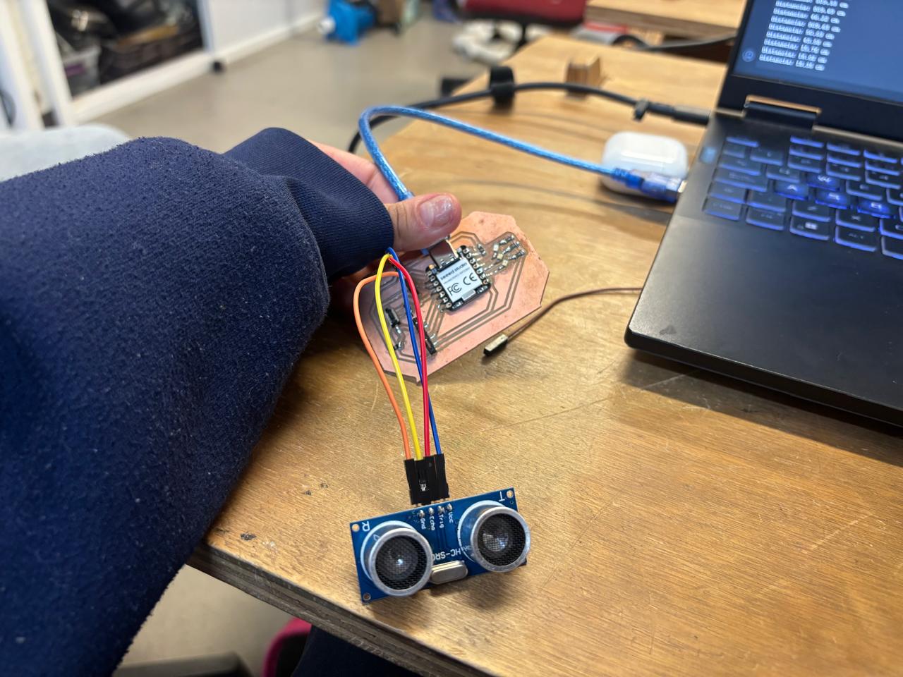
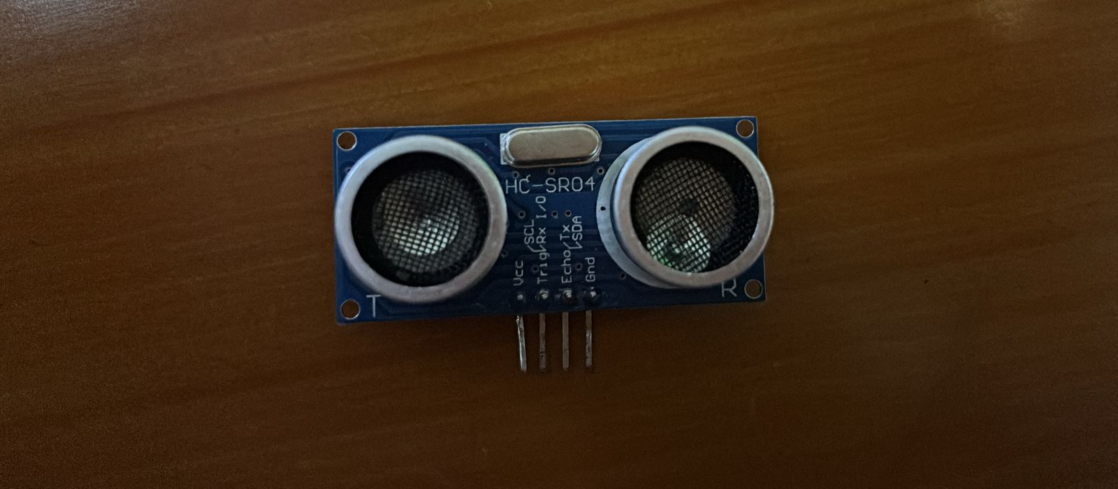
To choose the sensor I based it on what I want to do for my project. Based on that, I chose the HC-SR04 Ultrasonic Sensor. I think using this sensor will be very useful for my project, since I need to detect objects at certain distances so that my robot can evade them.
I considered that my XIAO RP2350 microcontroller works at 3.3V, however, the ultrasonic sensor works at 5V. This must be considered, since there could be a risk of burning the microcontroller if a higher voltage than the one it can operate with is used. In my case, I used a more current sensor that works with 3.3V.
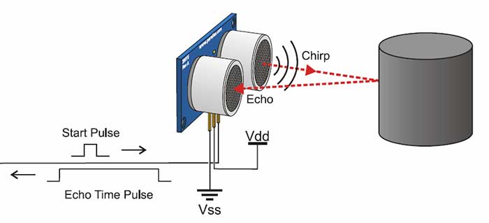
It is a sensor that measures distances using high-frequency sound waves. This basically works when the microcontroller sends a pulse (TRIG), the sensor emits ultrasound, the wave bounces off an object and returns to the sensor. From then on, the ECHO pin goes HIGH for a certain time, and through the time, the distance is obtained.
This type of sensor has two metallic cylinders, one is the transmitter (T) that works like a speaker, and a signal is sent through the Trig pin. While the other cylinder is the receiver, which works like a microphone. When the sound hits an object and bounces back, this cylinder hears it and sends a signal through the Echo pin.
The microcontroller counts the time that passed from when the sound went out until it returned. Based on this, in its programming, the constant speed at which sound travels through the air (343 meters per second) is considered.
The 3.3V version has a different chip, this one is designed to work with low voltages. This allows it to connect directly to my microcontroller without the need to build any circuit with resistors to lower the voltage. Finally, it can measure objects from 2 cm to 400 cm.
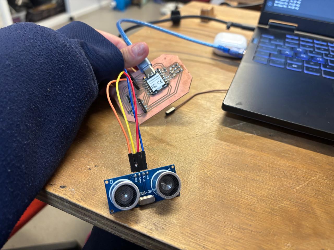
The pins I used on my board were the following: GND, 3.3V, D2 for Trig, and D1 for Echo. I specifically used D1 and D2, since these pins work as digital pins. I used female-female DuPont cables to connect the sensor and my PCB.
To program I used ARDUINO IDE, I installed it directly (you can download it here). It is not necessary to download any library, since it can be programmed manually. Based on how the sensor works and what was learned in week 4, I followed the following logic:
Definition of the XIAO pins, start of communication with the computer, configuration of the pin behavior (sound emission and input of the same), then a cycle to receive information. In that cycle, the Trig pin was cleared, then the ultrasonic pulse is triggered, then the time it took the Echo pin to receive the bounce is calculated, the distance is calculated, and the results are printed. Finally, I give a wait time before taking the next measurement.
The code for the ultrasonic sensor is as follows:
// Definimos los pines de la XIAO RP2350
// Usamos los pines etiquetados como A2 y A3 en tu placa
const int trigPin = D2; // Conectado al pin Trig del sensor
const int echoPin = D1; // Conectado al pin Echo del sensor

void setup() {
  // Iniciamos la comunicación con la computadora a 115200 baudios
  Serial.begin(115200);

  // Damos un par de segundos para que te dé tiempo de abrir el Monitor Serie
  delay(2000);
  Serial.println("Iniciando prueba del sensor ultrasónico HC-SR04...");

  // Configuramos el comportamiento de los pines
  pinMode(trigPin, OUTPUT); // El Trig emite el sonido (salida)
  pinMode(echoPin, INPUT);  // El Echo escucha el rebote (entrada)
}

void loop() {
  long duracion;
  float distancia;

  // 1. Limpiamos el pin Trig por seguridad poniéndolo en 0V
  digitalWrite(trigPin, LOW);
  delayMicroseconds(2);

  // 2. Disparamos un pulso ultrasónico rápido (10 microsegundos a 3.3V)
  digitalWrite(trigPin, HIGH);
  delayMicroseconds(10);
  digitalWrite(trigPin, LOW);

  // 3. Leemos cuánto tiempo tardó el pin Echo en recibir el rebote (en microsegundos)
  duracion = pulseIn(echoPin, HIGH);

  // 4. Calculamos la distancia en centímetros
  // (La velocidad del sonido es 0.0343 cm por microsegundo. Dividimos entre 2 porque el sonido va y regresa)
  distancia = (duracion * 0.0343) / 2.0;

  // 5. Imprimimos el resultado en el Monitor Serie
  Serial.print("Distancia: ");
  Serial.print(distancia);
  Serial.println(" cm");

  // Esperamos medio segundo antes de tomar la siguiente medida
  delay(500);
}
Finally, here a video can be shown where the measurements calculated by the program and the functioning of the sensor are observed.
Without a doubt, this week was very enriching. Essential electronics concepts were learned and recalled, such as types of pins, signals, and their applications. Similarly, for me, it was essential to understand how to use the pins and how they receive or send information. On the other hand, knowledge acquired in previous weeks, such as programming, electronics design, etc., was integrated.
If you want to access to my work from this week, please click here to download!
Finally, for the group assignment for this week, you can find the information here