14. Interface and Application Programming
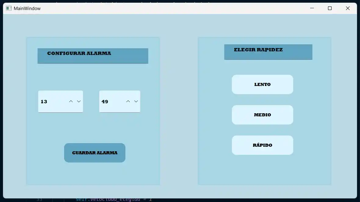
This week's assignment was to develop an interface to communicate with an input or output device. I decided to create an interface where the user could set the alarm time. To learn more about different ways to create an interface, you can check the GROUP PAGE.
For now, I am using an LED to simulate the alarm (which will be a speaker in my final project) and the user can select between 3 different modes.
The board I am using is the one I manufactured during WEEK8. To develop this interface, the first step was creating a virtual environment on my computer.
A virtual environment in Python serves to create isolated and secure spaces for each project, allowing the management of specific libraries and dependency versions without conflicts.
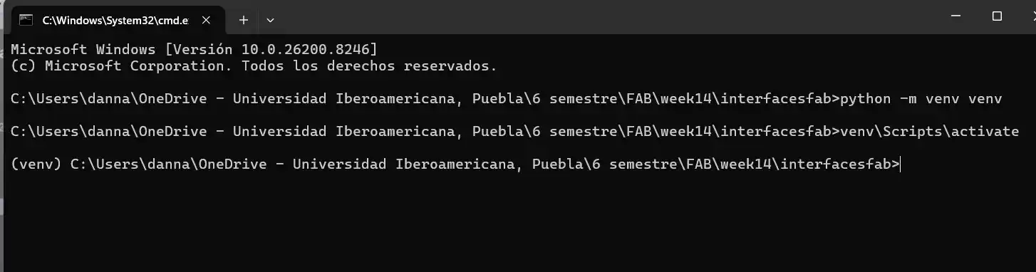
Creating a Virtual Environment
1.- Select the folder where the code will be located.
2.- Inside this folder, type cmd in the search bar to open the terminal directly in that path.
3.- Once in the terminal, use the following command to create the environment: python -m venv venv
4.- To activate it, use: venv\Scripts\activate
5.- Install the PyQt5 and pyserial libraries so Python can communicate with the serial port.
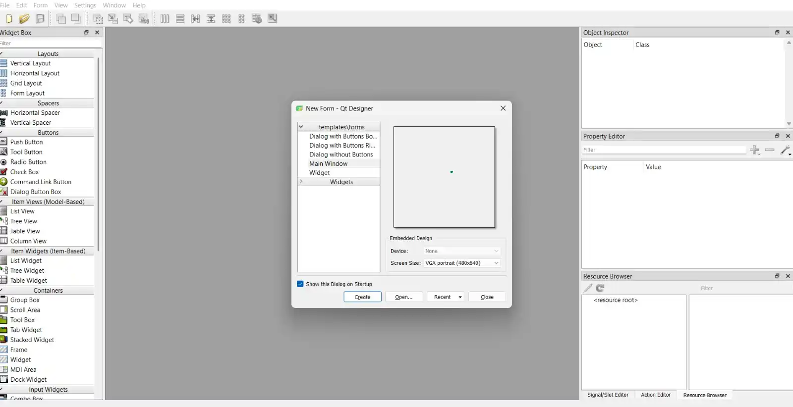
QT DESIGNER
For the visual development of the interface, I used QT Designer.
1.- Upon opening the software, a window appears to select a template. I chose "Main Window" with a screen view of (480x640).
2.- The main screen is divided into three sections:
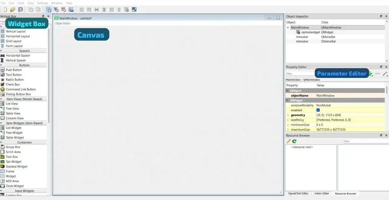
1. Widget Box: Where you select buttons, text boxes, etc.
2. Canvas: The area to edit the visual interface.
3. Parameter Editor: Used to change text styles, colors, and specific parameters.
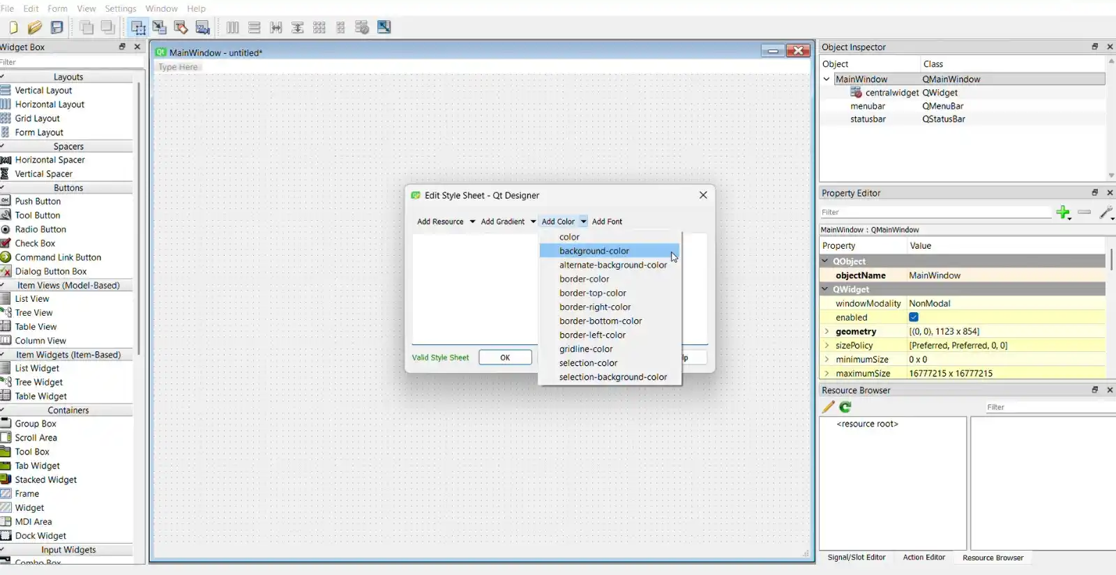
3.- I started by changing the background color: Right Click > Add Color > Background Color.
4.- After adding text boxes and buttons, I customized the format using CSS properties:
background-color: Expressed in RGB or Hexadecimal.
color: Changes font color.
border-radius: Expressed in px.
QPushButton:hover: Changes the style when the mouse hovers over it.
QPushButton:pressed: Changes the style when the button is clicked.
The final result of the interface design was:
PYTHON
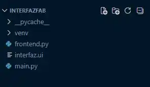
1.- I saved the .ui file from QT Designer in the project folder.
2.- In the terminal, I converted the .ui file to a .py file using: pyuic6 -x filename.ui -o output.py
Note: Avoid writing code directly in the generated file, as it will be overwritten if you change the UI. Use an independent file instead.
3.- I used this base structure to start the programming:
from frontend import *

class MainWindow(QtWidgets.QMainWindow, Ui_MainWindow):
    def __init__(self, *args, **kwargs):
        QtWidgets.QMainWindow.__init__(self, *args, **kwargs)
        self.setupUi(self)

if __name__ == "__main__":
    app = QtWidgets.QApplication([])
    window = MainWindow()
    window.show()
    app.exec()
4.- To read the serial port, I implemented the following block with the specific COM port and baud rate:
      try:
          self.arduino = serial.Serial('COM15', 115200, timeout=1)
          print("Successfully connected to the board!")
      except:
          print("Warning: Board not found. Check the cable and COM port.")
          self.arduino = None
5.- To run the code, I used: python name_file.py

PYTHON CODE
from PyQt6 import QtWidgets
from frontend import Ui_MainWindow
import serial
import sys

class MainWindow(QtWidgets.QMainWindow, Ui_MainWindow):
    def __init__(self, *args, **kwargs):
        super().__init__(*args, **kwargs)
        self.setupUi(self)

        # variable to save the blinking speed
        self.velocidad_elegida = 1

        # SERIAL CONNECTION
        try:
            self.arduino = serial.Serial('COM15', 115200, timeout=1)
            print("Successfully connected to the board!")
        except:
            print("Warning: Board not found. Check the cable and COM port.")
            self.arduino = None

        # Action to take depending on the button pressed
        self.sonido1.clicked.connect(self.elegir_lento)
        self.sonido2.clicked.connect(self.elegir_medio)
        self.sonido3.clicked.connect(self.elegir_rapido)
        self.guardaralarma.clicked.connect(self.enviar_alarma)

    # button functions
    def elegir_lento(self):
        self.velocidad_elegida = 1
        print("Selected option: SLOW")

    def elegir_medio(self):
        self.velocidad_elegida = 2
        print("Selected option: MEDIUM")

    def elegir_rapido(self):
        self.velocidad_elegida = 3
        print("Selected option: FAST")

    def enviar_alarma(self):
        # Read the numbers from the interface
        hora_seleccionada = self.horas.value()
        minuto_seleccionado = self.minutos.value()

        # save the data to be sent
        datos_a_enviar = f"{hora_seleccionada},{minuto_seleccionado},{self.velocidad_elegida}\n"

        # the data is sent
        if self.arduino and self.arduino.is_open:
            self.arduino.write(datos_a_enviar.encode('utf-8'))
            print(f"Alarm saved! Sent : {datos_a_enviar.strip()}")
        else:
            print("Error: Could not send the alarm because the board is not connected.")

if __name__ == "__main__":
    app = QtWidgets.QApplication(sys.argv)
    window = MainWindow()
    window.show()
    sys.exit(app.exec())
Explanation
Libraries and Imports
from PyQt6 import...: Imports the base modules of the Qt framework to create and manage the graphical interface.
import serial: Includes the pyserial library, which is essential for establishing physical communication via the USB/COM port with the board.
Class Initialization & Serial Setup
self.setupUi(self): Draws and initializes all the widgets (buttons, input boxes) that were visually created in QT Designer.
serial.Serial('COM15', 115200, timeout=1): Attempts to open the specific port (COM15) at the required communication speed (115200 baud rate).
try / except: Handles the connection safely. If the board isn't plugged in, the app catches the error, sets self.arduino = None, and keeps running normally instead of crashing the whole interface.
UI Connections & State Management
.clicked.connect(...): Links the user's physical clicks on the interface buttons to their corresponding background functions (like updating the speed or saving).
self.velocidad_elegida: Updates the internal speed variable to 1, 2, or 3 based on the button the user clicked, holding this state until the save button is pressed.
Output Control (Sending the Alarm)
.value(): Extracts the current integer values directly from the interface's time inputs (hours and minutes spinboxes).
f"{hora},{minuto},{velocidad}\n": Packages the three variables into a single text string separated by commas. The \n (line break) is injected at the end so the microcontroller knows exactly where the instruction packet ends.
self.arduino.write(datos.encode('utf-8')): First, it transforms the formatted text string into pure bytes and then physically pushes it through the serial port to the board.
ARDUINO CODE
#include <Wire.h>
#include "RTClib.h"

RTC_DS3231 rtc;

// Pins
const int botonPin = D9;
const int ledPin = D10;

// --- ALARM CONFIGURATION ---
const int MAX_ALARMAS = 10;

struct Alarma {
  int hora;
  int minuto;
  int velocidad; // mode: 1.- slow, 2.- medium, 3.- fast
  bool activa;
};

Alarma listaAlarmas[MAX_ALARMAS];
int totalAlarmasGuardadas = 0;

// States
bool alarmTriggered = false;
bool ultimoEstadoBoton = LOW;
int velocidadActual = 1;

// Function to save the alarm
void agregarAlarma(int h, int m, int v) {
  for (int i = 0; i < totalAlarmasGuardadas; i++) {
    if (listaAlarmas[i].hora == h && listaAlarmas[i].minuto == m && listaAlarmas[i].activa) {
      listaAlarmas[i].velocidad = v;
      Serial.println("Alarm updated with new speed.");
      return;
    }
  }

  if (totalAlarmasGuardadas < MAX_ALARMAS) {
    listaAlarmas[totalAlarmasGuardadas].hora = h;
    listaAlarmas[totalAlarmasGuardadas].minuto = m;
    listaAlarmas[totalAlarmasGuardadas].velocidad = v;
    listaAlarmas[totalAlarmasGuardadas].activa = true;
    totalAlarmasGuardadas++;
    Serial.printf("Alarm saved: %02d:%02d | Speed: %d\n", h, m, v);
  }
}

void setup() {
  Serial.begin(115200);
  pinMode(botonPin, INPUT_PULLDOWN);
  pinMode(ledPin, OUTPUT);
  digitalWrite(ledPin, LOW);

  Wire.begin();
  if (!rtc.begin()) {
    Serial.println("Error: RTC module not detected.");
    while (1);
  }

  if (rtc.lostPower()) {
    rtc.adjust(DateTime(F(__DATE__), F(__TIME__)));
  }
}

void loop() {
  // 1. READ SERIAL DATA
  if (Serial.available() > 0) {
    String datos = Serial.readStringUntil('\n');
    int primeraComa = datos.indexOf(',');
    int segundaComa = datos.lastIndexOf(',');

    if (primeraComa != -1 && segundaComa != -1) {
      int h = datos.substring(0, primeraComa).toInt();
      int m = datos.substring(primeraComa + 1, segundaComa).toInt();
      int v = datos.substring(segundaComa + 1).toInt();
      agregarAlarma(h, m, v);
    }
  }

  // 2. CHECK TIME
  DateTime now = rtc.now();

  if (!alarmTriggered && now.second() == 0) {
    for (int i = 0; i < totalAlarmasGuardadas; i++) {
      if (listaAlarmas[i].activa && now.hour() == listaAlarmas[i].hora && now.minute() == listaAlarmas[i].minuto) {
        alarmTriggered = true;
        velocidadActual = listaAlarmas[i].velocidad;
        listaAlarmas[i].activa = false;
        Serial.println("Alarm triggered!");
        break;
      }
    }
    delay(1000);
  }

  // 3. EXECUTE ALARM
  if (alarmTriggered) {
    int tiempoParpadeo = 1000;
    if (velocidadActual == 2) tiempoParpadeo = 400;
    else if (velocidadActual == 3) tiempoParpadeo = 100;

    digitalWrite(ledPin, HIGH);
    delay(tiempoParpadeo);
    digitalWrite(ledPin, LOW);
    delay(tiempoParpadeo);
  }

  // 4. DEACTIVATE ALARM (BUTTON)
  bool lecturaBoton = digitalRead(botonPin);
  if (lecturaBoton == HIGH && ultimoEstadoBoton == LOW) {
    delay(50); // Debounce
    if (alarmTriggered) {
      alarmTriggered = false;
      digitalWrite(ledPin, LOW);
      Serial.println("Button pressed! Alarm deactivated.");
    }
  }
  ultimoEstadoBoton = lecturaBoton;
}
Explanation
Libraries and Data Structures
#include <Wire.h> and "RTClib.h": These libraries are essential for communicating with the DS3231 RTC module via the I2C protocol.
struct Alarma: I created a custom structure to group all the details of a single alarm: the hour, minute, blinking speed, and an active state flag. This makes it easy to store multiple alarms in the listaAlarmas array (up to 10).
Parsing Serial Data
Serial.readStringUntil('\n'): The board waits for the exact data string sent by the Python interface and stops reading when it finds the line break.
.indexOf(',') and .substring(): Since the data arrives as a single text string (e.g., "14,30,2"), these functions find the commas and cut the text into three separate pieces. .toInt() then converts those text pieces back into integers so the microcontroller can use them to set the time and speed.
RTC Time Checking
DateTime now = rtc.now(): Constantly gets the current time from the physical module.
if (!alarmTriggered && now.second() == 0): To prevent the alarm from triggering multiple times within the same minute, it only checks the array when the seconds are exactly zero. If the current hour and minute match a saved alarm, it sets alarmTriggered = true and grabs that specific alarm's speed.
Hardware Outputs & Inputs
tiempoParpadeo: When the alarm triggers, a series of if/else statements check the selected speed (1, 2, or 3) and adjust the delay() time (1000ms, 400ms, or 100ms) to make the LED blink slower or faster.
digitalRead(botonPin): Continuously checks the physical button. The delay(50) acts as a debounce to prevent false double-clicks. If pressed while the alarm is ringing, it switches alarmTriggered to false and forces the LED off.