Prior Knowledge
What I knew before this week:
- I already knew how to design and fabricate custom electronic boards from scratch using KiCad, the MonoFab SRM-20 milling machine, and the soldering process — all of which I practiced extensively during Weeks 9 and 10.
- I knew how to use microcontrollers to process a basic input or output: reading a sensor, turning on an LED, or driving a motor. But each board always worked on its own — isolated, with no communication to the outside world.
- I had no previous knowledge of networking protocols, wireless communication between boards, MQTT, brokers, or how one microcontroller can send a command to another over a network.
Group Assignment
Group Page
- Send a message between two projects.
- Document your work on the group work page and reflect on your individual page what you learned.
What I learned from the group assignment:
- I learned that there are many different ways to communicate between devices, and that the right choice depends entirely on the project's needs: distance, number of devices, speed, and whether a network infrastructure is already available.
- I understood the fundamental difference between protocols like UART (point-to-point, wired, no network needed) and MQTT (wireless, broker-based, scalable to many devices).
- I learned that MQTT is especially well-suited for IoT scenarios because it is lightweight, works over standard WiFi, and does not require a direct connection between the two communicating devices — they only need to agree on a topic name and a broker address.
- Comparing protocols side by side helped me understand that "communication" in embedded systems is not just about sending bytes, but about choosing an architecture that matches the scale and constraints of the project.
Boards Used This Week
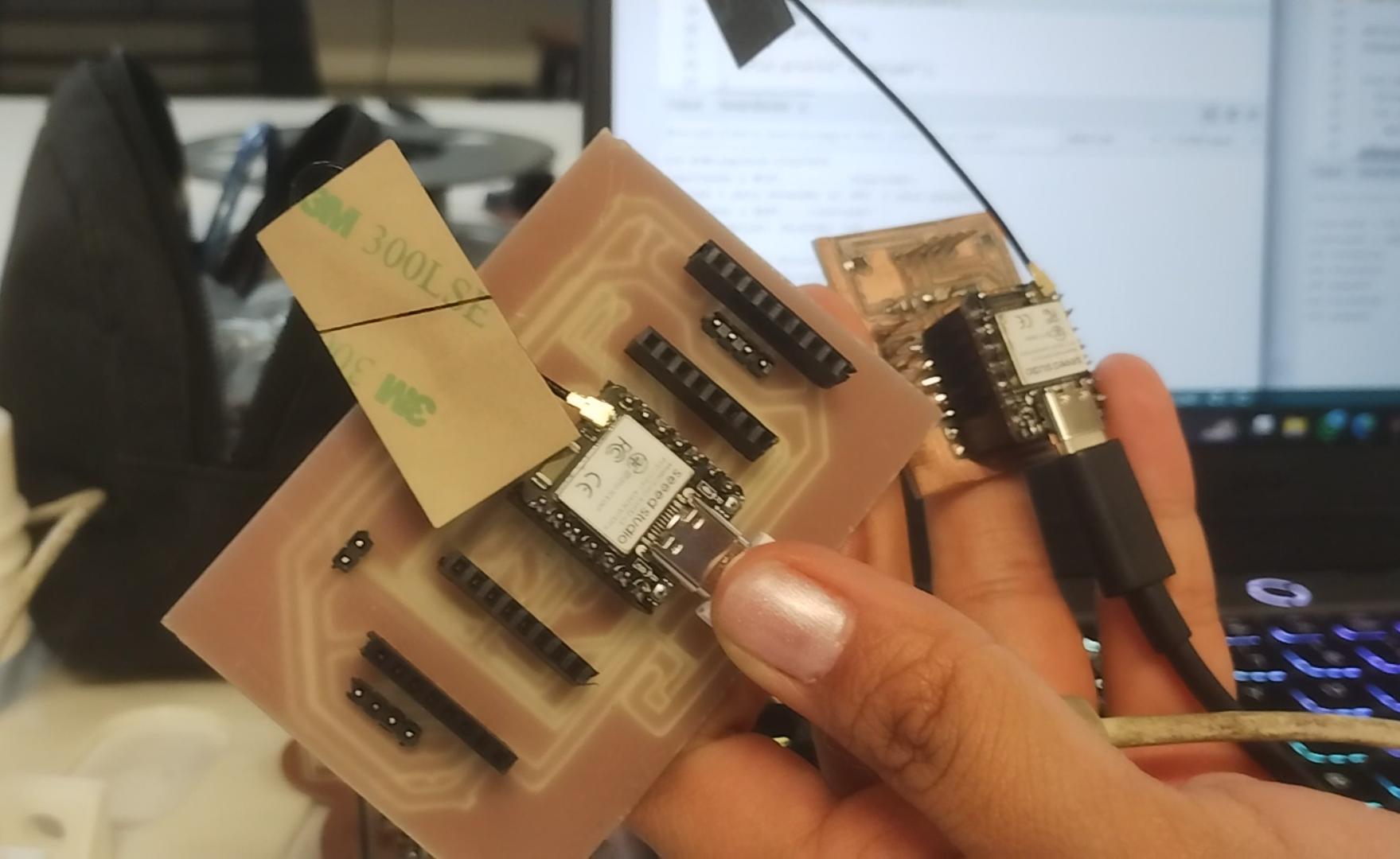
For this week's individual assignment I used two boards that I had designed and fabricated in previous weeks. Both are based on the Seeed Studio XIAO family of microcontrollers, which share the same compact form factor and operate at 3.3V logic — making them directly compatible with each other over WiFi without any level-shifting hardware.
Board 1 — "Helper Board" (Sender / Publisher)
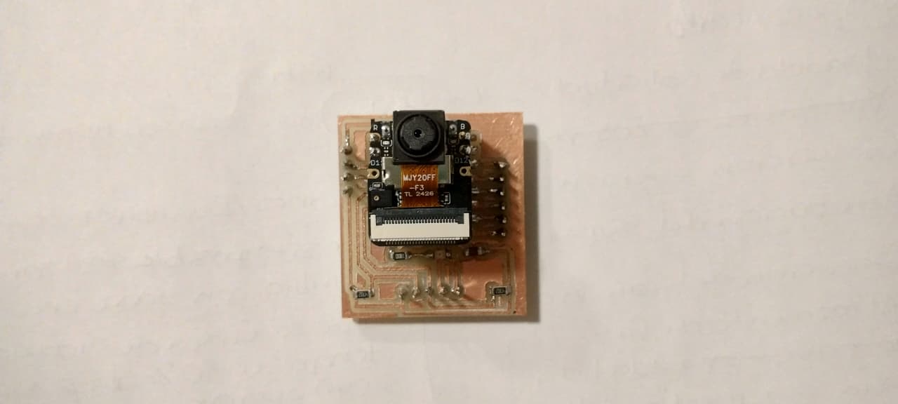
This board was designed and fabricated during Week 09 — Input Devices. Its original purpose was to read a camera using AI-based person detection (SenseCraft), but for this week it was repurposed as the sender in the MQTT communication: it reads input from the Serial Monitor and publishes commands to the broker.
Microcontroller: XIAO ESP32-S3
- Processor: Dual-core Xtensa LX7 @ 240 MHz
- WiFi: 802.11 b/g/n (2.4 GHz only)
- Logic voltage: 3.3V
- Flash: 8 MB
- Camera support: Yes (OV2640 via CSI connector)
- Role this week: Publisher — reads Serial Monitor input and publishes MQTT commands
Helper board (XIAO ESP32-S3) designed in Week 09 — used as the publisher this week.
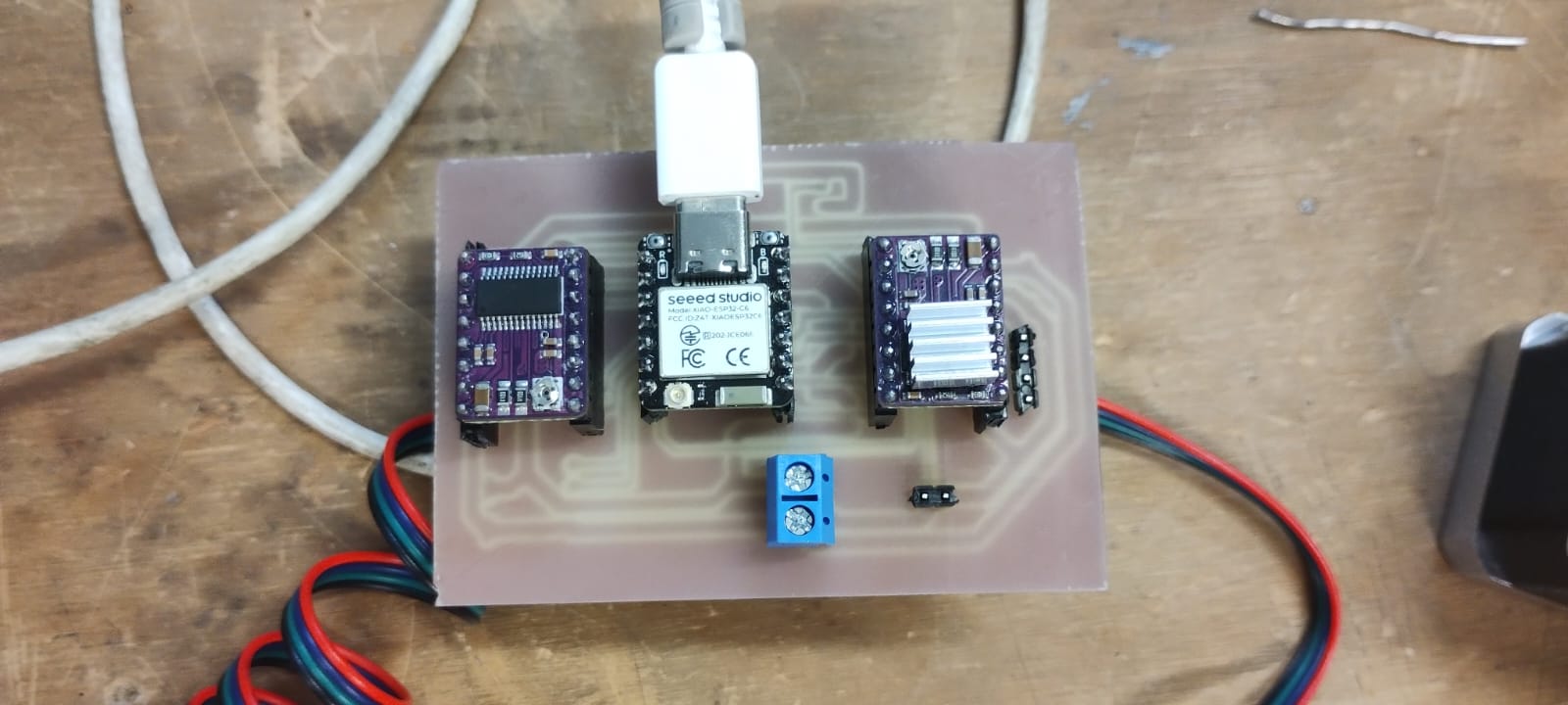
Board 2 — "LED Board" (Receiver / Subscriber)
This board was designed and fabricated during Week 10 — Output Devices. Its original purpose was to control two stepper motors using DRV8825 drivers, but for this week its LED (connected to GPIO 43 / D6) was used as the output that responds to the MQTT commands received over WiFi.
Microcontroller: XIAO ESP32-C6
- Processor: Single-core RISC-V @ 160 MHz
- WiFi: 802.11 b/g/n (2.4 GHz), also supports WiFi 6 (802.11ax)
- Logic voltage: 3.3V
- Flash: 4 MB
- Role this week: Subscriber — receives MQTT commands and turns its LED on or off
- LED pin: GPIO 43 (D6 in XIAO notation)
LED board (XIAO ESP32-C6) designed in Week 10 — used as the subscriber this week.
Important — WiFi Antenna: Both XIAO boards have a connector for an external WiFi antenna (IPEX/U.FL connector). The antenna must be physically plugged in before trying to connect to a WiFi network. Without it, the signal is too weak to reach the router reliably, and the board will fail to connect or drop the connection repeatedly. This was one of the problems I encountered during this week (see the Problems section). Connecting the antenna solved the issue immediately.
Physical Connection — How Are the Two Boards Linked?
Unlike I2C or UART (which require physical wires between boards), MQTT communicates entirely over WiFi. The two boards are not connected to each other with any wire. They only share:
- The same WiFi network (2.4 GHz)
- The same MQTT broker address (
broker.hivemq.com) - The same topic string (
ibero/led/control)
Both boards connect to the broker independently, and the broker handles routing the message from the publisher to the subscriber. This is the key advantage of MQTT: the two devices never need to know each other's IP address or be in the same physical location.
What is MQTT and How Does It Work?
MQTT (Message Queuing Telemetry Transport) is a lightweight messaging protocol designed for devices with limited resources — like microcontrollers — that need to communicate over an unreliable or bandwidth-constrained network. It was originally developed by IBM in the 1990s for monitoring oil pipelines via satellite, and was released as an open standard in 2010. Today it is one of the most widely used protocols in IoT (Internet of Things) applications.
The Publish / Subscribe Model
The fundamental idea behind MQTT is different from the classic client-server model (like HTTP). Devices never talk to each other directly. Instead, they all connect to a central server called a broker, which handles routing messages between them.
The pattern works as follows:
- A device that wants to send a message is called a Publisher. It sends a message to the broker addressed to a specific Topic (a string like
ibero/led/control). - A device that wants to receive messages is called a Subscriber. It tells the broker "I want everything published to this topic." From then on, any message published to that topic gets forwarded to it automatically.
- The Broker is the middleman. It never stores data permanently — it only routes messages from publishers to the subscribers that asked for them.
- The Topic is a hierarchical string used as the routing key. A topic like
ibero/led/controlmeans: namespace ibero, subtopic led, channel control. Topics can have unlimited levels separated by/. - The Payload is the actual content of the message — in my case, plain text strings like
"ENCENDER"or"APAGAR".
Key Concepts Summary:
| Concept | Definition | My project's value |
|---|---|---|
| Broker | Central server that routes messages between clients | broker.hivemq.com (free public broker) |
| Topic | A string that identifies the channel for a message | ibero/led/control |
| Publisher | The device that sends a message to a topic | Helper board (XIAO ESP32-S3) |
| Subscriber | The device that receives all messages from a topic | LED board (XIAO ESP32-C6) |
| Payload | The actual content of the message | "ENCENDER" or "APAGAR" |
| Port | The TCP port used for the connection | 1883 (standard MQTT TCP) |
Why MQTT Instead of Direct Communication?
A reasonable question is: why not just have the two boards talk to each other directly over WiFi? The answer is that MQTT's broker model provides several practical advantages:
- The devices don't need to know each other's IP address. In a real network, IP addresses can change. With MQTT, both boards only need to know the broker's address.
- It scales naturally. If later I want a third board to also react to the LED command, I simply subscribe it to the same topic — no changes to the sender's code.
- It works across any network. As long as both boards can reach the internet, they can communicate even if they are in different buildings or cities.
- The protocol is lightweight. MQTT messages have very small headers, making it efficient for microcontrollers with limited RAM and processing power.
HiveMQ — The Public Broker I Used
For this project I used the free public broker provided by HiveMQ at broker.hivemq.com on port 1883. This broker requires no registration, no authentication, and no setup — you just point your code at it and it works immediately. It is ideal for learning and prototyping. The only caveat is that since it is public, anyone who knows your topic name could also subscribe to it, so it should not be used for sensitive data in production.
MQTT Communication Diagram
The diagram below shows exactly how the two boards communicate in my project. I made it so it is easier to understand the flow of information before reading the code.
MQTT Communication Flow — Week 11
in Serial Monitor
"ENCENDER" or "APAGAR"to topic
ibero/led/controlNo auth required
Routes messages
by topic
ibero/led/control"ENCENDER" → LED ON"APAGAR" → LED OFF
in its Serial Monitor
Physical setup: both boards connected to the computer via USB-C for power and Serial Monitor, communicating wirelessly through the HiveMQ broker.
Problem 1 — Choosing the wrong protocol first: I2C instead of MQTT.
My initial plan for this week was to communicate the two boards using the I2C protocol (one board as master, one as slave). However, I ran into multiple issues: the RP2350 bootloader required a manual BOOT+RESET sequence every time I uploaded code, the I2C wiring (SDA, SCL, GND, plus pull-up resistors) was more complex to set up, and after several failed upload attempts I decided to switch entirely to MQTT, which only requires WiFi (no physical wires between boards) and is simpler to debug.
Solution: Switched to MQTT and replaced the RP2350 + ESP32-S3 pair with an ESP32-S3 (helper board) + ESP32-C6 (LED board) pair — both from my Weeks 9 and 10 boards — since both support WiFi natively.
The Code
Installing the Required Library
Both boards only need one external library: PubSubClient by Nick O'Leary, which implements the MQTT protocol on ESP32. The WiFi library is already included with the ESP32 board package.
- Open Arduino IDE.
- Go to Tools → Manage Libraries (or press
Ctrl + Shift + I). - Search for "PubSubClient" by Nick O'Leary and click Install.
Board Configuration in Arduino IDE
| Board | Arduino IDE Selection | Board Package |
|---|---|---|
| Helper Board (XIAO ESP32-S3) | XIAO_ESP32S3 |
esp32 by Espressif Systems |
| LED Board (XIAO ESP32-C6) | XIAO_ESP32C6 |
esp32 by Espressif Systems |
The only lines you need to change in both sketches are the WiFi credentials. Everything else (broker, port, topic, logic) works as-is.
const char* WIFI_SSID     = "TU_RED_WIFI";      // ← your 2.4 GHz network name
const char* WIFI_PASSWORD = "TU_PASSWORD_WIFI"; // ← your WiFi password
Remember: both boards must be on the same 2.4 GHz network, and the antenna must be physically connected to the IPEX connector on each board.
Code Intention
The project is divided into two independent sketches — one per board:
- Helper Board (Publisher): Connects to WiFi and the broker, then waits for the user to type
1or2in the Serial Monitor. When it detects input, it publishes either"ENCENDER"or"APAGAR"to the shared topic. It also prints a confirmation message in its own Serial Monitor. - LED Board (Subscriber): Connects to WiFi and subscribes to the topic. Whenever a message arrives, the callback function reads the payload: if it says
"ENCENDER", the LED turns on and prints "Led encendido"; if it says"APAGAR", the LED turns off and prints "Led apagado". The LED state is maintained indefinitely until the next command arrives.
Helper Board Code — Publisher (XIAO ESP32-S3)
#include <WiFi.h>              // ESP32 built-in WiFi library
#include <PubSubClient.h>      // MQTT client library — install via Library Manager

// ── WiFi credentials ─────────────────────────────────────────────────────────
const char* WIFI_SSID     = "TU_RED_WIFI";      // CHANGE: your 2.4 GHz network name
const char* WIFI_PASSWORD = "TU_PASSWORD_WIFI"; // CHANGE: your WiFi password

// ── MQTT broker settings ──────────────────────────────────────────────────────
const char* MQTT_BROKER = "broker.hivemq.com";  // Free public HiveMQ broker
const int   MQTT_PORT   = 1883;                 // Standard TCP port for MQTT (not WebSocket)

// ── Topic ─────────────────────────────────────────────────────────────────────
const char* TOPIC_LED = "ibero/led/control";    // Channel used to send commands to the LED board

// ── MQTT client objects ───────────────────────────────────────────────────────
WiFiClient   wifiClient;                        // Underlying TCP connection object
PubSubClient mqttClient(wifiClient);            // MQTT client built on top of the WiFi connection

// ── WiFi connection function ──────────────────────────────────────────────────
void conectarWiFi() {
  Serial.print("Connecting to WiFi...");
  WiFi.begin(WIFI_SSID, WIFI_PASSWORD);          // Start the WiFi handshake
  while (WiFi.status() != WL_CONNECTED) {        // Block here until connected
    delay(500);
    Serial.print(".");                           // Print dots as a progress indicator
  }
  Serial.println(" Connected!");                 // Success message
}

// ── MQTT reconnection function ────────────────────────────────────────────────
void reconectarMQTT() {
  while (!mqttClient.connected()) {              // Keep trying until the connection succeeds
    Serial.print("Connecting to MQTT...");
    // Generate a random client ID to avoid conflicts with other users of the same broker
    String clientId = "placa_ayuda_" + String(random(0xffff), HEX);
    if (mqttClient.connect(clientId.c_str())) {  // Attempt connection with the random ID
      Serial.println(" Connected!");             // Broker accepted the connection
    } else {
      Serial.print(" Failed (rc=");
      Serial.print(mqttClient.state());          // Print the error code for debugging
      Serial.println("). Retrying in 3s...");
      delay(3000);                               // Wait 3 seconds before the next attempt
    }
  }
}

// ── setup() — runs once on power-on ──────────────────────────────────────────
void setup() {
  Serial.begin(115200);                          // Open Serial Monitor at 115200 baud
  conectarWiFi();                                // Connect to WiFi first
  mqttClient.setServer(MQTT_BROKER, MQTT_PORT);  // Point the MQTT client at the broker
  Serial.println("Type 1 to turn the LED ON, 2 to turn it OFF:");
}

// ── loop() — runs continuously ────────────────────────────────────────────────
void loop() {
  if (!mqttClient.connected()) reconectarMQTT(); // Reconnect if the broker dropped us
  mqttClient.loop();                             // Process incoming MQTT events (mandatory)

  if (Serial.available()) {                      // Check if the user typed something
    char input = Serial.read();                  // Read exactly one character

    if (input == '1') {                          // User typed "1"
      mqttClient.publish(TOPIC_LED, "ENCENDER"); // Publish the ON command to the topic
      Serial.println("Message sent: Turn LED on");
    }
    else if (input == '2') {                     // User typed "2"
      mqttClient.publish(TOPIC_LED, "APAGAR");   // Publish the OFF command to the topic
      Serial.println("LED off");
    }
  }
}
LED Board Code — Subscriber (XIAO ESP32-C6)
#include <WiFi.h>              // ESP32 built-in WiFi library
#include <PubSubClient.h>      // MQTT client library — install via Library Manager

// ── WiFi credentials ─────────────────────────────────────────────────────────
const char* WIFI_SSID     = "TU_RED_WIFI";      // CHANGE: your 2.4 GHz network name
const char* WIFI_PASSWORD = "TU_PASSWORD_WIFI"; // CHANGE: your WiFi password

// ── MQTT broker settings ──────────────────────────────────────────────────────
const char* MQTT_BROKER = "broker.hivemq.com";  // Must match the publisher's broker exactly
const int   MQTT_PORT   = 1883;                 // Must match the publisher's port exactly

// ── Topic ─────────────────────────────────────────────────────────────────────
const char* TOPIC_LED = "ibero/led/control";    // Must match the publisher's topic exactly

// ── LED pin ───────────────────────────────────────────────────────────────────
#define LED_PIN 43                              // GPIO 43 = D6 on the XIAO ESP32-C6 pinout

// ── MQTT client objects ───────────────────────────────────────────────────────
WiFiClient   wifiClient;                        // Underlying TCP connection object
PubSubClient mqttClient(wifiClient);            // MQTT client built on top of the WiFi connection

// ── Message callback — runs every time a subscribed message arrives ───────────
void onMessage(char* topic, byte* payload, unsigned int length) {
  String mensaje = "";
  for (unsigned int i = 0; i < length; i++) {
    mensaje += (char)payload[i];               // Convert byte array to String character by character
  }

  if (mensaje == "ENCENDER") {                  // Command received: turn LED on
    digitalWrite(LED_PIN, HIGH);               // Set GPIO 43 HIGH (LED on)
    Serial.println("Led encendido");           // Confirm in Serial Monitor
  }
  else if (mensaje == "APAGAR") {               // Command received: turn LED off
    digitalWrite(LED_PIN, LOW);                // Set GPIO 43 LOW (LED off)
    Serial.println("Led apagado");             // Confirm in Serial Monitor
  }
}

// ── WiFi connection function ──────────────────────────────────────────────────
void conectarWiFi() {
  Serial.print("Connecting to WiFi...");
  WiFi.begin(WIFI_SSID, WIFI_PASSWORD);          // Start the WiFi handshake
  while (WiFi.status() != WL_CONNECTED) {        // Block here until connected
    delay(500);
    Serial.print(".");
  }
  Serial.println(" Connected!");
}

// ── MQTT reconnection function ────────────────────────────────────────────────
void reconectarMQTT() {
  while (!mqttClient.connected()) {
    Serial.print("Connecting to MQTT...");
    // Random client ID prevents conflicts on the shared public broker
    String clientId = "placa_led_" + String(random(0xffff), HEX);
    if (mqttClient.connect(clientId.c_str())) {  // Attempt connection
      Serial.println(" Connected!");
      mqttClient.subscribe(TOPIC_LED);           // Subscribe to the topic AFTER connecting
                                                 // (subscriptions must be re-done after every reconnect)
    } else {
      Serial.print(" Failed (rc=");
      Serial.print(mqttClient.state());          // Error code: -2 = broker unreachable, -4 = timeout
      Serial.println("). Retrying in 3s...");
      delay(3000);
    }
  }
}

// ── setup() — runs once on power-on ──────────────────────────────────────────
void setup() {
  Serial.begin(115200);                          // Open Serial Monitor
  pinMode(LED_PIN, OUTPUT);                      // Configure GPIO 43 as a digital output
  digitalWrite(LED_PIN, LOW);                    // Start with LED off
  conectarWiFi();                                // Connect to WiFi
  mqttClient.setServer(MQTT_BROKER, MQTT_PORT);  // Configure the broker
  mqttClient.setCallback(onMessage);             // Register the message handler function
}

// ── loop() — runs continuously ────────────────────────────────────────────────
void loop() {
  if (!mqttClient.connected()) reconectarMQTT(); // Maintain the MQTT connection
  mqttClient.loop();                             // Process incoming messages (mandatory — without
                                                 // this line, the callback never fires)
}
What You See in the Serial Monitor
Both boards print status messages to their Serial Monitors independently. Here is what a successful session looks like, and what each line means.
Helper Board (Publisher) — Serial Monitor Output
Connecting to WiFi......... Connected!
Type 1 to turn the LED ON, 2 to turn it OFF:

[After typing "1":]
Message sent: Turn LED on

[After typing "2":]
LED off- "Connecting to WiFi....... Connected!" — The dots appear one by one every 500ms while the board is negotiating the WiFi connection. Once it gets an IP address, "Connected!" is printed.
- "Type 1 to turn the LED ON, 2 to turn it OFF:" — Printed in
setup(), right after the MQTT client is configured. From this point the board is waiting for user input. - "Message sent: Turn LED on" — Confirms that
mqttClient.publish()was called with the"ENCENDER"payload. This does NOT confirm that the LED board received it — only that the helper board successfully sent it to the broker. - "LED off" — Same confirmation for the
"APAGAR"command.
LED Board (Subscriber) — Serial Monitor Output
Connecting to WiFi......... Connected!
Connecting to MQTT... Connected!

[When ENCENDER command arrives:]
Led encendido

[When APAGAR command arrives:]
Led apagado- "Connecting to MQTT... Connected!" — Printed inside
reconectarMQTT()after the broker accepts the connection. Note that the subscription toibero/led/controlhappens immediately after this, inside the same function. - "Led encendido" — Printed inside the
onMessage()callback when the payload"ENCENDER"is received from the broker. At this exact moment,digitalWrite(LED_PIN, HIGH)is also called. - "Led apagado" — Same, for the
"APAGAR"payload.
How the Two Boards Communicate — Step by Step
- Both boards power on and connect to the same WiFi network independently.
- Both boards connect to
broker.hivemq.com:1883using a randomly generated client ID. - The LED board calls
mqttClient.subscribe("ibero/led/control")— from now on, the broker will forward any message on that topic to it. - The user opens the Serial Monitor on the Helper board and types
1. - The Helper board calls
mqttClient.publish("ibero/led/control", "ENCENDER")— this sends the payload to the broker. - The broker identifies that the LED board is subscribed to
ibero/led/controland forwards the message. - The LED board's
mqttClient.loop()detects the incoming message and fires theonMessage()callback. - Inside the callback,
digitalWrite(43, HIGH)turns the LED on and "Led encendido" is printed.
Important: The call to mqttClient.loop() inside loop() is absolutely mandatory on the subscriber. Without it, the board never processes incoming packets and the callback never fires — the LED would never respond, even if the message arrives at the broker correctly.
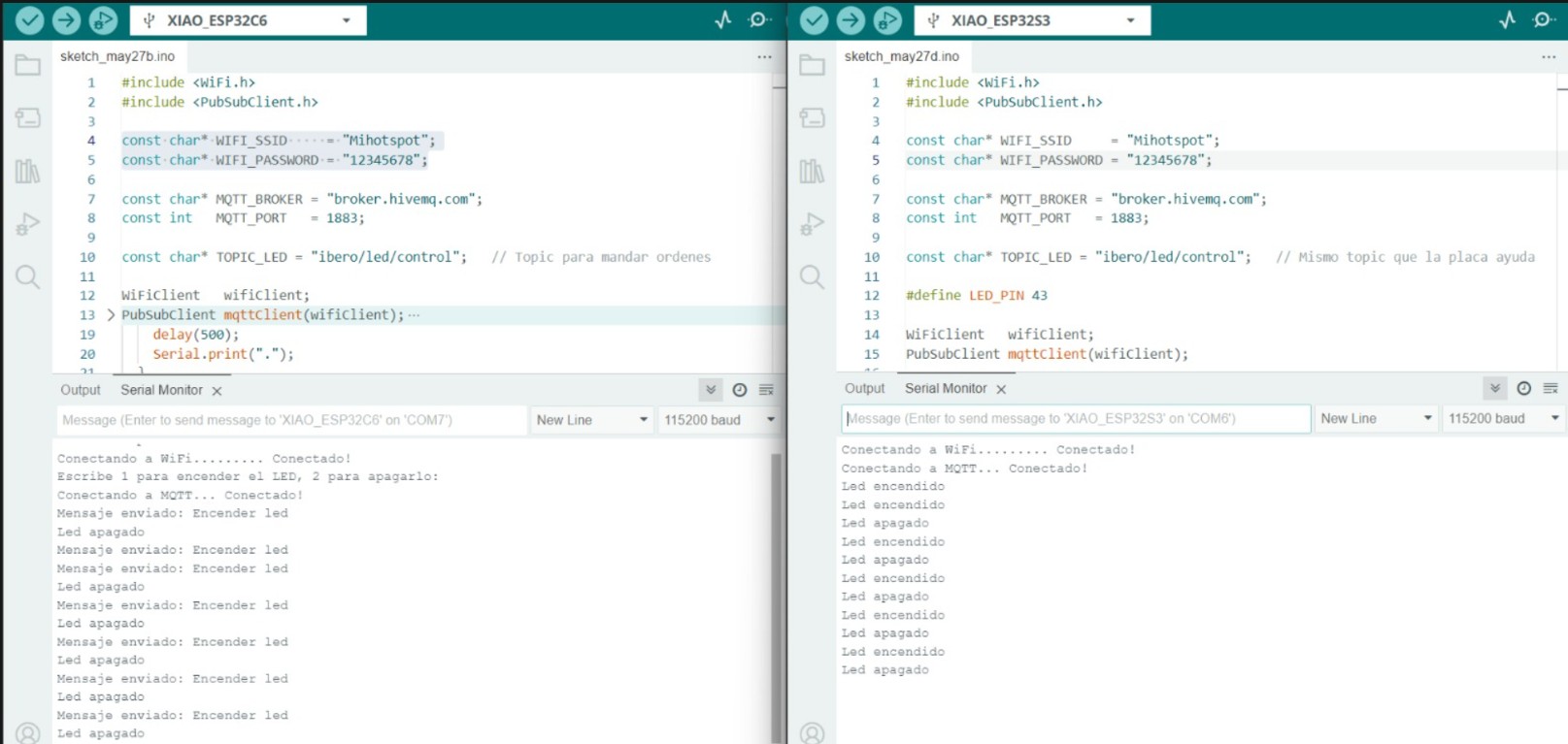
Serial Monitor output on both boards during a successful communication session. Note: in this screenshot the ESP32-C6 window appears on the publisher side and the ESP32-S3 on the subscriber side — the inverse of the role assignment documented in the text. The code and functionality are correct; only the window layout in the capture is swapped.
Problem 2 — Serial Monitor showed rc=-2 and the board never connected to the broker.
After uploading the subscriber code to the LED board, the Serial Monitor kept printing "Connecting to MQTT... Failed (rc=-2). Retrying in 3s..." indefinitely. The error code -2 means the broker is unreachable — the board could not establish a TCP connection to broker.hivemq.com:1883.
There were two root causes:
- The external WiFi antenna was not connected. The XIAO ESP32-C6 and S3 both have a small IPEX/U.FL connector for an external antenna. Without it physically plugged in, the WiFi signal is too weak to reliably reach the router — especially if the board is on a desk surrounded by other electronics. The board would sometimes connect to WiFi but immediately fail to reach the internet.
- The WiFi network was 5 GHz. Both XIAO boards only support 2.4 GHz WiFi. Connecting to a 5 GHz SSID causes the connection to silently fail.
Solution: Connected the antenna to the IPEX connector on each board, and switched the WiFi SSID in the code to my phone's hotspot (2.4 GHz). Both boards connected immediately after.
Problem 3 — The LED board received the message but the LED did not turn on.
After fixing the connection issues, the Serial Monitor on the LED board showed "Led encendido" correctly, but the physical LED did not light up.
Solution: I had forgotten to add pinMode(LED_PIN, OUTPUT) in setup(). Without this line, the pin defaults to high-impedance input mode and digitalWrite() has no effect. Adding pinMode(43, OUTPUT) fixed it immediately.
Problem 4 — Uploading code to the XIAO RP2350 (from the initial I2C attempt) failed with "No drive to deploy".
When I tried to upload any sketch to the RP2350, Arduino IDE compiled successfully but the upload failed at the end with "Scanning for RP2040 devices — No drive to deploy".
Solution: The RP2350 requires a manual bootloader entry: hold the BOOT button (B), then press and release RESET (R), then release BOOT. The board then appears as a USB mass storage drive and Arduino IDE can upload. This is a one-time quirk of the RP2350 that does not affect ESP32-based boards.
Results
Below are two videos that show the final system working. The first shows the Serial Monitor screens of both boards during a live communication session. The second shows the physical boards and the LED responding to the commands.
[Video 1 — Serial Monitor view: typing "1" on the helper board triggers the LED board's response in real time.]
[Video 2 — Physical boards: the LED on the ESP32-C6 board turns on and off in response to MQTT commands sent from the ESP32-S3 board.]
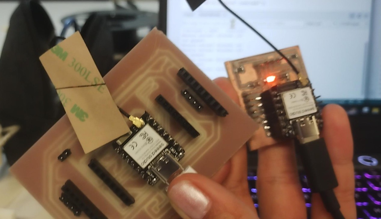
Hero shot: both boards on the workbench, communicating wirelessly over MQTT through the HiveMQ broker.
What I learned this week:
- I learned how MQTT works as a publish/subscribe messaging system, and how a public broker like HiveMQ acts as a wireless bridge between two microcontrollers without any physical wires connecting them.
- I learned the importance of the external WiFi antenna on XIAO boards — without it, WiFi signal is too weak to reach the broker reliably, and the board shows
rc=-2errors indefinitely. - I understood why
mqttClient.loop()is mandatory in the subscriber'sloop()function — it is the mechanism that processes incoming packets and fires the message callback. - I reused two boards I had already designed and fabricated in Weeks 9 and 10, which showed me that a well-designed board can be reprogrammed for completely different tasks without any hardware modifications.
- Most importantly, I crossed the threshold from "boards that work in isolation" to "boards that communicate with each other" — which is the foundation of any real IoT system.
Files I used this week
W11_files.zip
Networking and Communications Files
The following files are included in the package:
- helper_board/helper_board.ino: Arduino sketch for the XIAO ESP32-S3 (publisher).
- led_board/led_board.ino: Arduino sketch for the XIAO ESP32-C6 (subscriber).
- Board design files for Week 09: See Week 09 page.
- Board design files for Week 10: See Week 10 page.