Schematic Editor
Group Page
- Measure the power consumption of an output device.
- Document your work on the group work page and reflect on your individual page what you learned.
What I knew before this week:
- Thanks to previous weeks, I was already familiar with the board fabrication process.
- I had never worked with any type of motor, although I knew their internal workings from a previous course.
- I had no prior experience with output devices, so this topic is completely new to me.
Board Purpose: The purpose of the board is to control two stepper motors using DRV8825 drivers.
Software Used
| # | Software | Use |
|---|---|---|
| 1 | KiCad | Board design (Schematic Capture & PCB Design). |
| 2 | Modsproject CE | Converting SVG files to machine files (MonoFab). |
| 3 | VPanel for SRM-20 | Operating the MonoFab machine. |
| 4 | Arduino IDE | Software to program my ESP32 S3. |
Materials
| Component | Qty | Value / Model | Library / Footprint |
|---|---|---|---|
| A2_M2, A3_M1B1 | 2 | Pololu Breakout DRV8825 | Module:Pololu_Breakout-16 |
| C1 | 1 | 10 μF (C_1206) | PCM_fab:C_1206 |
| C2, C3 | 2 | Electrolytic 100uF (Panasonic) | PCM_fab:CP_Elec_100uF |
| J1 | 1 | Screw Terminal (01x02) | PCM_fab:TerminalBlock_OnShore |
| J2, J3, J4 | 3 | Pin Header 1x04 (Vertical) | PCM_fab:PinHeader_01x04_P2.54mm |
| J6 | 1 | Pin Header 1x02 (Vertical) | PCM_fab:PinHeader_01x02_P2.54mm |
| M1 | 1 | XIAO ESP32-C3 | PCM_fab:SeeedStudio_XIAO_ESP32C3 |
| R1 - R10 | 10 | Resistor 1206 (0 Ω for jumpers) | PCM_fab:R_1206 |
| U1 | 1 | AMS1117 Regulator | Package_TO_SOT_SMD:SOT-223 |
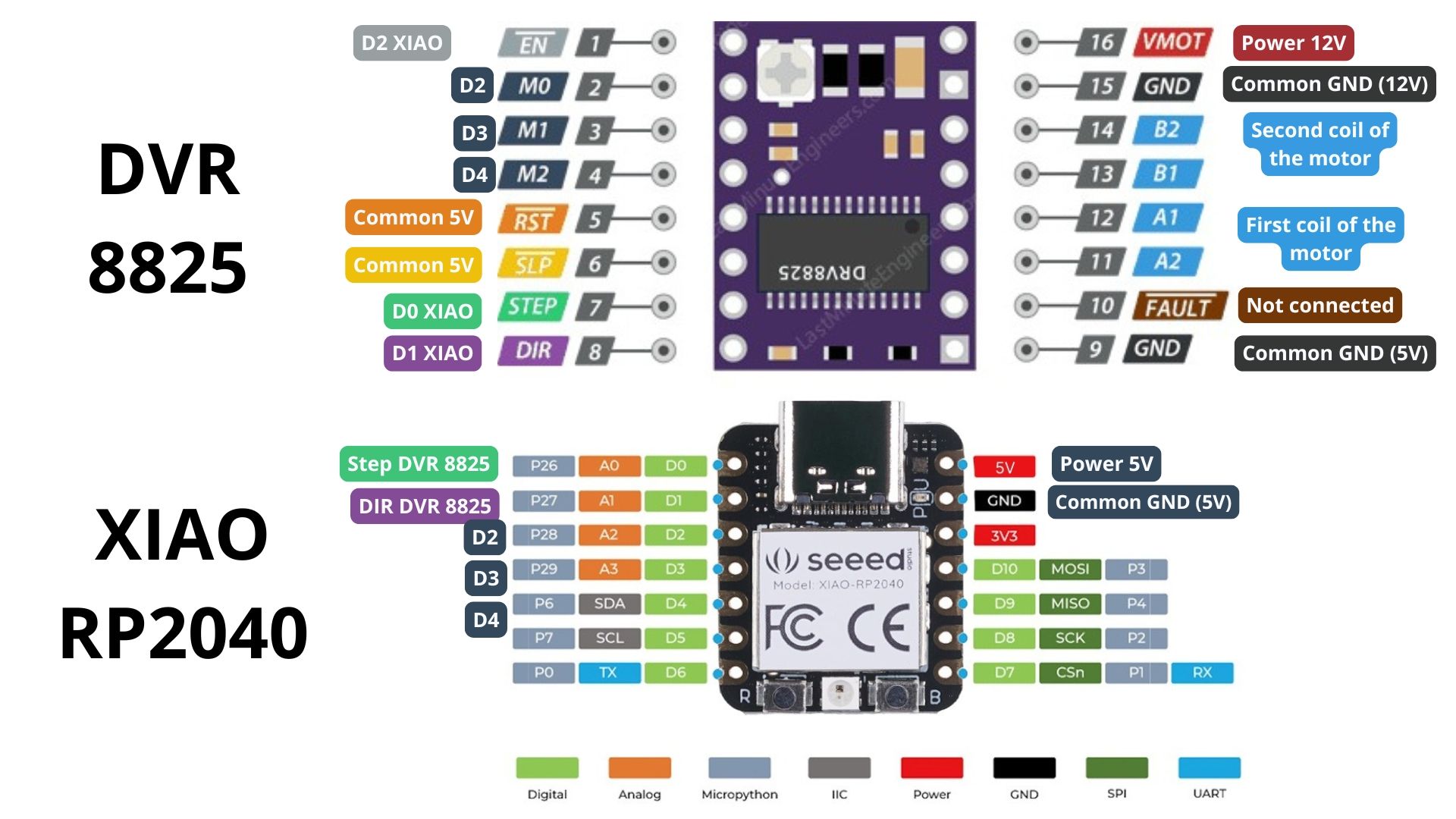
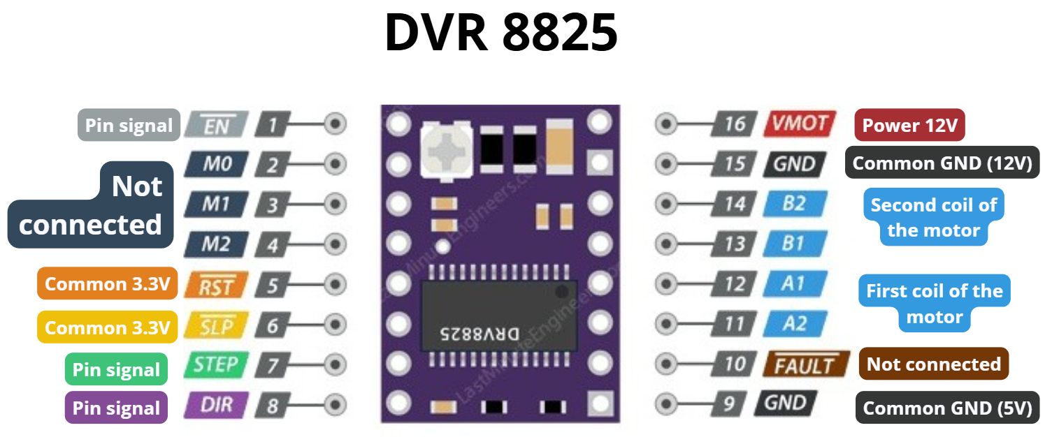
DRV8825 Driver
For this project, the DRV8825 driver was used, which features 16 pins with specific functions for motor control:
- Enable: Connected to an output on the XIAO ESP32-C6.
- M0, M1, M2: Control micro-stepping; each goes to a different digital output on the XIAO.
- Reset & Sleep: Connected together internally to the 3.3V source.
- Step: Receives the step count from a XIAO pin.
- Dir: Defines the rotation direction from a XIAO pin.
- VMOT: Direct power input (12V) for the motors.
- GND: Two common grounds connected together.
- B2, B1, A1, A2: Outputs connected to the stepper motor coils.
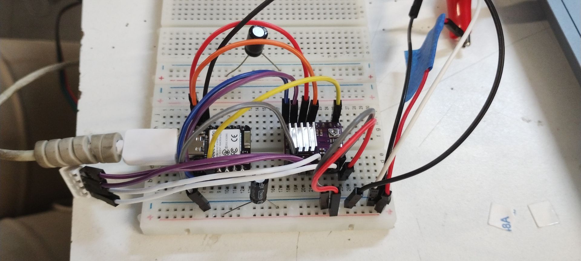
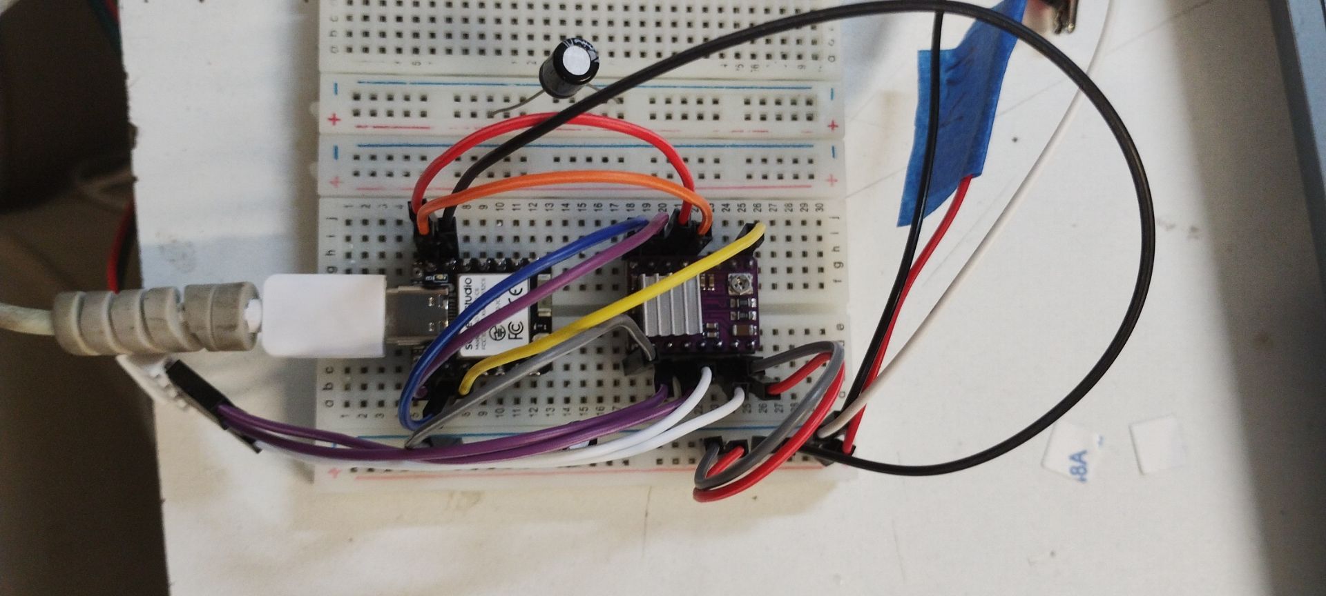
Breadboard Testing
Recommendation: When working with unknown components, always check the datasheet for connection diagrams and test the circuit on a breadboard first to verify functionality before manufacturing the PCB.
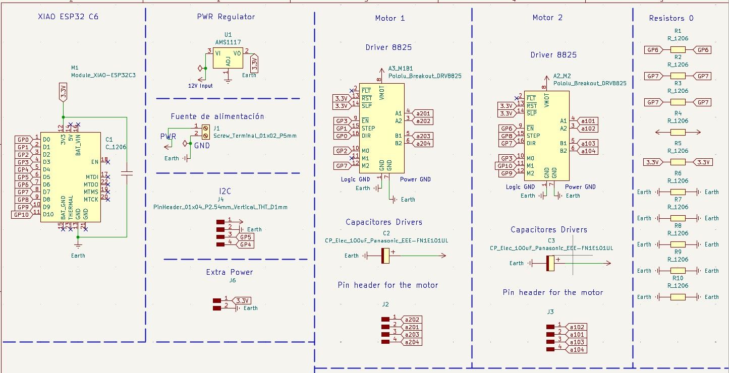
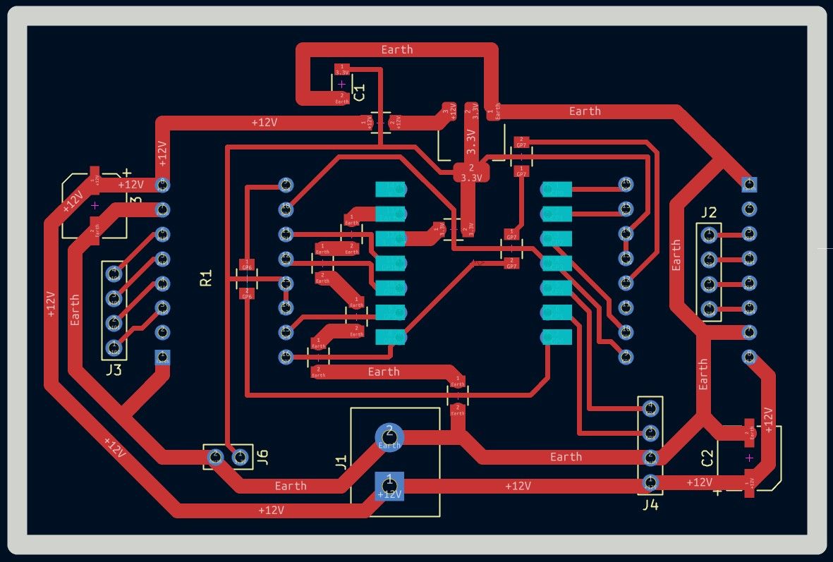
Final Schematic
Board Editor
KiCad Optimization: I discovered an option to pre-configure track widths, which saves significant time during design.
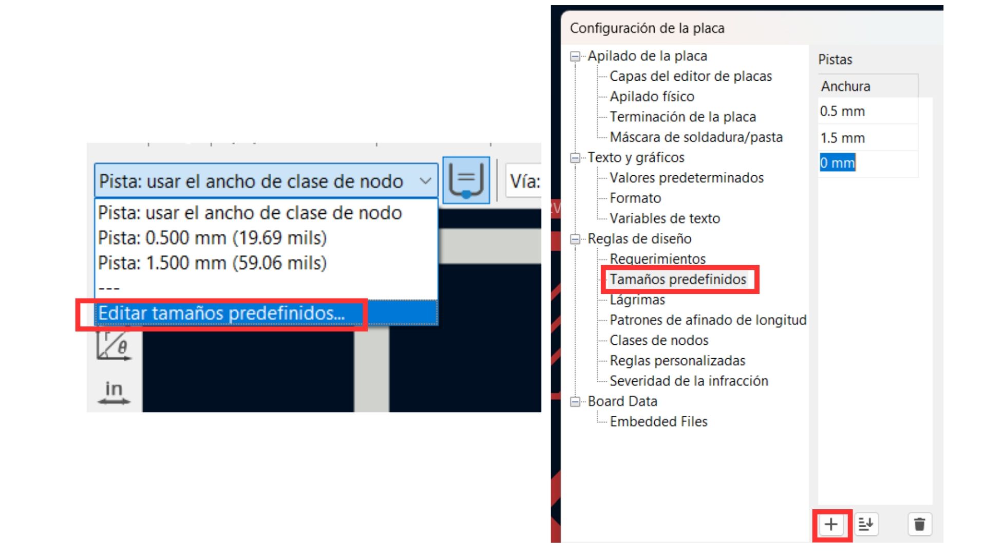
Predefined track configuration.
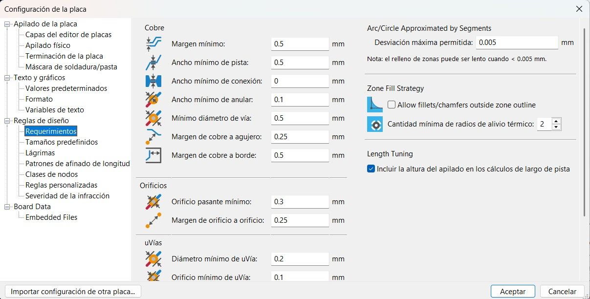
Design rules must set the minimum value among all defaults to avoid errors.
New Techniques Applied
Trace Widths: I configured 0.8 mm for signal lines (ESP32S3 and 3.3V) and 1.5 mm for power lines (12V and GND) to handle higher current loads and prevent overheating.

"Flip" Technique for Through-hole Components
To make soldering easier on a single-sided board, I placed the female pins (for drivers and MCU) on the back side. This allows the pins to pass through the board to be soldered comfortably on the copper side.
Design Note: This must be done before routing, as flipping creates a mirror effect on the pin layout.
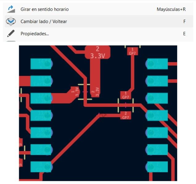
Pin layout after applying the flip technique.
Routing Challenges
Managing connections for the DRV8825 was the biggest challenge due to the high density of pins, which caused traces to cross frequently.
How I solved my routing problem:
Managing connections for the DRV8825 was a complex task due to the high density of pins and the need for thick power traces (1.5mm). I encountered two main obstacles:
- Trace Intersections: To resolve the frequent crossing of signal lines without using a double-sided board, I implemented zero-ohm resistors (R1-R10) as jumpers. This allowed me to "hop" over power traces while maintaining the signal integrity of the micro-stepping and enable lines.
- The Vref Tuning Loop: During the hardware setup, I noticed the motors were vibrating but not turning. The solution was a precise calibration using a multimeter. I placed the positive probe on the driver's potentiometer and the negative probe on GND, adjusting until reaching 0.6V. This specific value provides the necessary 1.2A current (71% of nominal) required for the NEMA 17 to overcome its holding torque.
NOTE: In electronics design, this is not considered the cleanest or most formal industry practice, but it is an incredibly useful and practical workaround for single-sided boards.
Final Board Layout
Results
Hero Shots
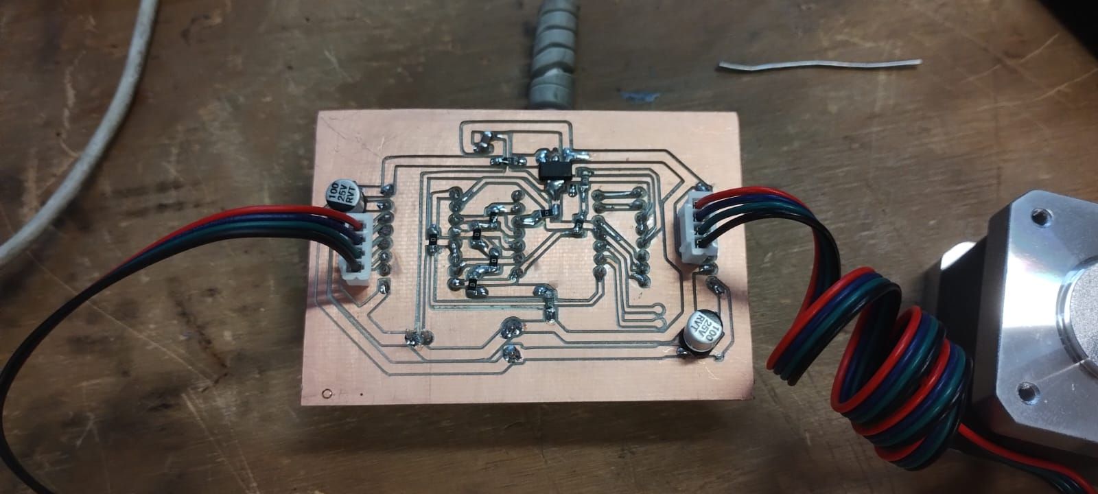
[Front View]
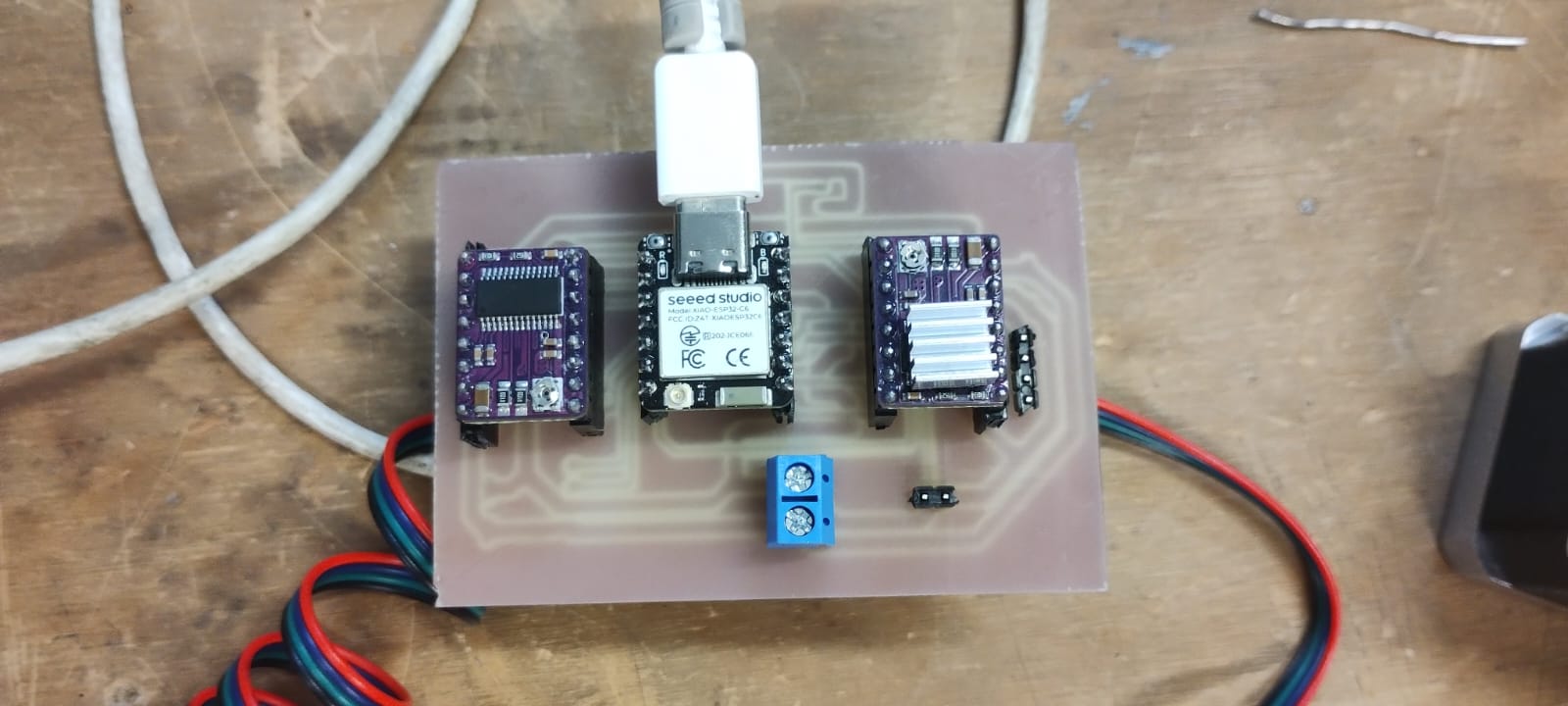
[Front View]
Stepper Motor Operation
[Video 1: Board in operation]
[Video 2: Stepper motors working]
[Video 3: Arduino IDE app Screen]
Power consumption
Power Control and Calibration: DRV8825
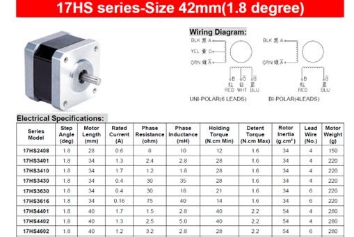
To control the NEMA 17 stepper motors (model 17HS4401), I used the DRV8825 driver[cite: 1]. One of the fundamental characteristics of this module is its ability to manage independent power supplies: a low-voltage logic signal for communication with the microcontroller and a high-power supply for motor movement[cite: 1].
Current Adjustment via Vref
To ensure optimal operation and avoid thermal damage, it is crucial to limit the current that the driver delivers to the motor[cite: 1]. The DRV8825 features a precision potentiometer (adjustable with a screwdriver) that regulates the reference voltage (Vref)[cite: 1]:
- Clockwise: Reduces the amperage delivered[cite: 1].
- Counter-clockwise: Increases the amperage delivered[cite: 1].
Theoretical Calculation of Reference Voltage (Vref)
Based on the motor's datasheet, the maximum current is 1.7A[cite: 1]. However, to protect the driver and improve efficiency, it is recommended to work at a safety current (Ichop), usually calculated at 71% of the motor's total capacity[cite: 1].
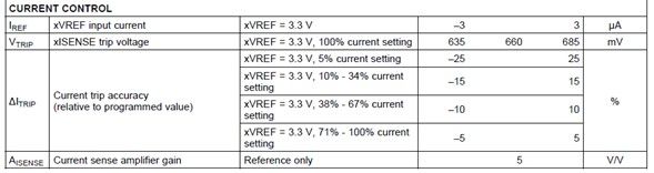
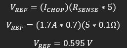
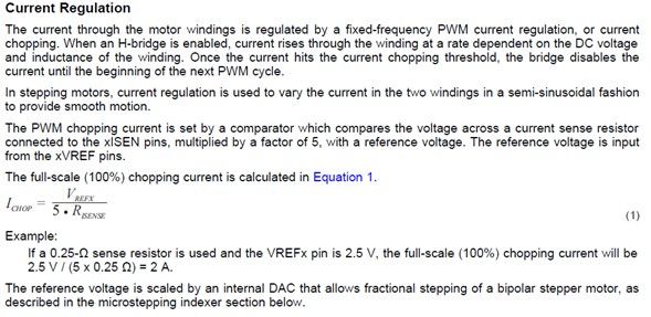
We use the formula provided by the driver manufacturer[cite: 1]:
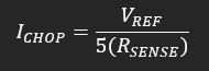
Where:
- Rsense: Is the value of the sensing resistor on the module (commonly 0.100 in standard models)[cite: 1].
- Ichop: Is 71% of the nominal current (1.7A × 0.71 = 1.207A)[cite: 1].
By knowing most values and solving for Vref (which is the value we must measure with the multimeter on the potentiometer), we ensure the driver's longevity[cite: 1]. If the value is too low, it won't work; if it's too high, there is a risk of burning the driver or the motor[cite: 1].
Final Vref value set to approximately 0.6V.
Physical Measurements & Power Analysis
| Measured Value | Description | |
|---|---|---|
| Voltage (V) | 12.04 V | Steady supply voltage from the external power source. |
| Current (I) | 1.18 A | Measured in series during a full rotation cycle (peak current). |
| Power (P) | 14.20 W | Calculated total power consumption (P = V \times I). |
These values confirm that the motor is operating within the safety margins defined by the 0.6V Vref, preventing the DRV8825 from triggering its thermal shutdown.
Importance of Calibration
Setting the Vref to approximately 0.6V is vital for two reasons[cite: 1]:
- Undercurrent: If the voltage is too low, the motor will not have enough torque and will lose steps[cite: 1].
- Overcurrent: If the voltage is excessive, the driver will overheat quickly, activating its thermal protection or permanently damaging the motor windings[cite: 1].
What I learned this week:
- I learned to design a PCB to control two stepper motors with DRV8825 drivers, differentiating trace widths for signals (0.8 mm) and for 12V power/GND lines (1.5 mm) to handle higher current without overheating.
- I learned the "Flip" technique in KiCad to place through-hole components on the back of the board, facilitating soldering from the copper side on single-sided boards.
- I learned to calibrate the DRV8825 potentiometer by calculating the correct Vref (≈0.6V) using the datasheet formula, knowing that a voltage too low won't move the motor and one too high will burn the driver.
What I learned from the group page:
- I learned that all motor types (DC, servo, and stepper) require an external power source and a driver IC, as they demand much more current than a GPIO pin can safely provide.
- I understood that stepper motors consume current even at rest (holding current), which generates heat; therefore, it is advisable to disable the driver when holding is not necessary.
- I learned to use three measurement instruments depending on the context: the USB Tester for USB-powered devices, the multimeter in series for measuring current in non-USB circuits, and the clamp meter for high currents without opening the circuit.
Code Used
Breadboard Test (Two Drivers)
Note: In this test, pins M0, M1, and M2 were not connected.
#include  // Includes the AccelStepper library for advanced, non-blocking motor control with acceleration ramps

#define STEP_PIN_1    D1  // Maps GPIO D1 to control the speed and step generation of Driver 1 via square-wave pulses
#define DIR_PIN_1     D0  // Maps GPIO D0 to set the rotation direction of Motor 1 (HIGH for clockwise, LOW for CCW)
#define ENABLE_PIN_1  D3  // Maps GPIO D3 to manage the power state of Driver 1's internal coil bridges
#define STEP_PIN_2    D8  // Maps GPIO D8 to control the speed and step generation of Driver 2 via square-wave pulses
#define DIR_PIN_2     D7  // Maps GPIO D7 to set the rotation direction of Motor 2 (HIGH for clockwise, LOW for CCW)
#define ENABLE_PIN_2  D6  // Maps GPIO D6 to manage the power state of Driver 2's internal coil bridges

#define FULL_STEPS_PER_REV 200 // Defines the physical motor resolution (standard 1.8 degree step angle equals 200 full steps per revolution)
#define MICROSTEP          1   // Set to 1 because M0, M1, and M2 pins are disconnected, defaulting the driver to Full-Step mode

const long TEST_STEPS = FULL_STEPS_PER_REV * MICROSTEP; // Calculates total step pulses needed for one full 360-degree rotation (200 * 1 = 200)
const float MAX_SPEED  = 1000.0; // Sets the velocity upper limit to 1000 steps per second to prevent high-speed motor stalling
const float ACCEL      = 2000.0; // Sets the acceleration slope to 2000 steps/sec^2 to ramp speed smoothly up and down
const float CONT_SPEED = 750.0;  // Establishes a fallback constant target velocity of 750 steps per second for continuous rotation

AccelStepper stepper1(AccelStepper::DRIVER, STEP_PIN_1, DIR_PIN_1); // Instantiates Motor 1 object using the 2-wire hardware driver interface
AccelStepper stepper2(AccelStepper::DRIVER, STEP_PIN_2, DIR_PIN_2); // Instantiates Motor 2 object using the 2-wire hardware driver interface

bool continuousMode = false; // Declares a state flag variable to toggle between precise positioning (false) and endless rotation (true)

void enableDrivers(bool enable) {
  digitalWrite(ENABLE_PIN_1, enable ? LOW : HIGH); // Uses ternary operator: drives pin LOW (0V) to turn on Driver 1 since ENABLE is Active-Low
  digitalWrite(ENABLE_PIN_2, enable ? LOW : HIGH); // Uses ternary operator: drives pin LOW (0V) to turn on Driver 2 since ENABLE is Active-Low
}

void setup() {
  Serial.begin(115200);         // Initializes the hardware serial interface at 115,200 baud rate for low-latency communication
  pinMode(ENABLE_PIN_1, OUTPUT); // Configures Driver 1 enable pin as a digital output to send control signals
  pinMode(ENABLE_PIN_2, OUTPUT); // Configures Driver 2 enable pin as a digital output to send control signals
  enableDrivers(true);           // Calls custom function to pull active-low enable pins to 0V, energizing the motor coils instantly
  stepper1.setMaxSpeed(MAX_SPEED);   // Binds the maximum velocity ceiling constraint to the Motor 1 software instance
  stepper1.setAcceleration(ACCEL);   // Binds the kinematic acceleration ramp constraint to the Motor 1 software instance
  stepper2.setMaxSpeed(MAX_SPEED);   // Binds the maximum velocity ceiling constraint to the Motor 2 software instance
  stepper2.setAcceleration(ACCEL);   // Binds the kinematic acceleration ramp constraint to the Motor 2 software instance
}

void loop() {
  if (Serial.available()) { // Polls the serial ring-buffer to verify if any incoming bytes are waiting to be processed
    char cmd = Serial.read(); // Reads the oldest single character from the buffer and stores it in the local variable 'cmd'
    switch (cmd) { // Evaluates the value of the character command to branch execution paths
      case '1': continuousMode = false; stepper1.moveTo(stepper1.currentPosition() + TEST_STEPS); stepper2.moveTo(stepper2.currentPosition() + TEST_STEPS); break; // Resets mode flag, reads current position coordinates, adds 200 steps, and schedules target trajectories
      case '0': continuousMode = false; stepper1.stop(); stepper2.stop(); break; // Resets mode flag and computes a dynamic deceleration ramp to bring motors to a smooth halt
    }
  }
  if (continuousMode) { stepper1.runSpeed(); stepper2.runSpeed(); } // If flag is true, executes step pulses at constant velocity without using acceleration slopes
  else { stepper1.run(); stepper2.run(); } // The default core engine: continuously calculates and executes step pulses if mathematically required at this exact millisecond to follow the acceleration curves and reach target positions
}
Code Logic & Function Breakdown
p>The firmware uses theAccelStepper library because it manages pulses in the background, allowing for non-blocking acceleration ramps. Here is the technical breakdown:
- AccelStepper Object:
AccelStepper::DRIVERtells the library to use a dedicated Step/Dir driver (DRV8825) instead of manual phase switching. - The 'Enable' Logic: The ENABLE_PIN is configured as Active-Low. This is because the DRV8825 internal circuitry is designed to pull the pin to ground to activate
- '1': Triggers
moveTo(), calculating the required pulses for one full revolution ($200 \text{ steps} \times 1 \text{ microstep}$). - '0': Calls
stop(), which calculates a rapid deceleration ramp to bring the motor to a safe halt without losing position.
- '1': Triggers
- The run() function: This is the "engine" of the code. It must be called every loop to check if a step pulse is due. If
runSpeed()is used instead, the motor ignores acceleration and moves at a constant velocity.
Files I used this week
These are the files I utilized for my assignments this week.
w10_output_files.zip
Output Devices Files
- KiCad Project: Design files
- SVG Files: For fabrication
- Mods Files: RML for MonoFab
- Arduino Code: Test scripts