PCB Redesign
I had to redesign the PCB practically from scratch. The entire process and its documentation can be found in Week 06 of Electronics Design.
Ways to make a PCB:
- With the "Mono Fab" machine
- X Tool machine: It is mainly used for laser engraving, but it is possible to engrave with it; however, it is more complicated.
- Vinyl cutting: Using copper tape to trace the routes.
Note: Do not place on a metal base as it will cause a short circuit.
Software to use
Note: To access the links, click on the file type in the third column.
| Software | Use | File Type |
|---|---|---|
| Gerber2PNG |
|
Website (Gerber2Png | Fablab Kerala) |
| Modsproject.org |
|
Website (mods CE) |
| VPanel for SRM-20 |
|
Website (mods CE) Note: Licensed software that comes with the machine. |
| Arduino IDE 2 |
|
Microsoft Store Link |
1. In KiCad
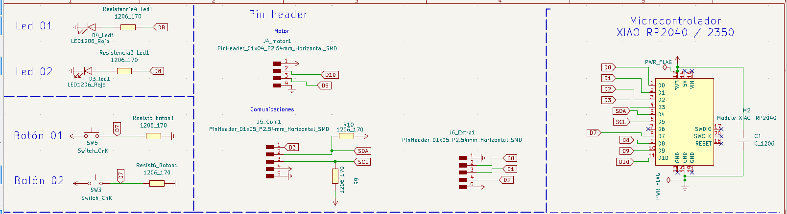
Board Schematic
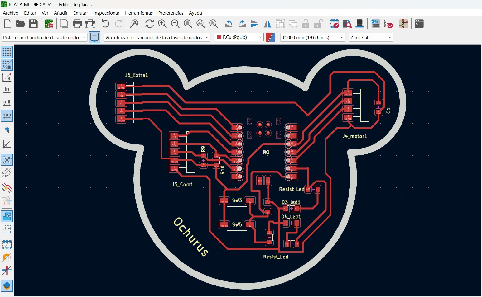
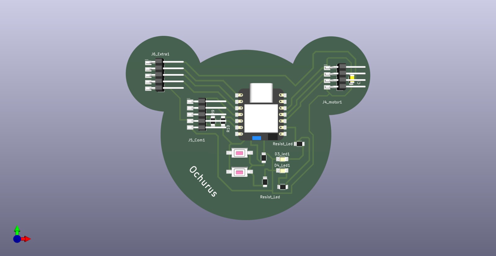
Connected Board
Process in KiCad
1. Save the board document
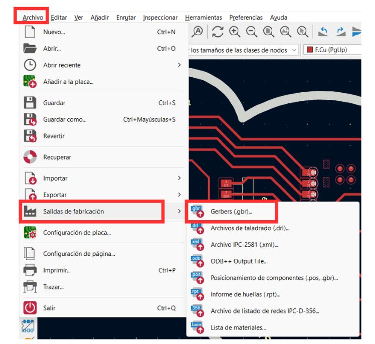
First, the board must be saved as follows: Save > Fabrication Outputs > Gerbers (.gbr)
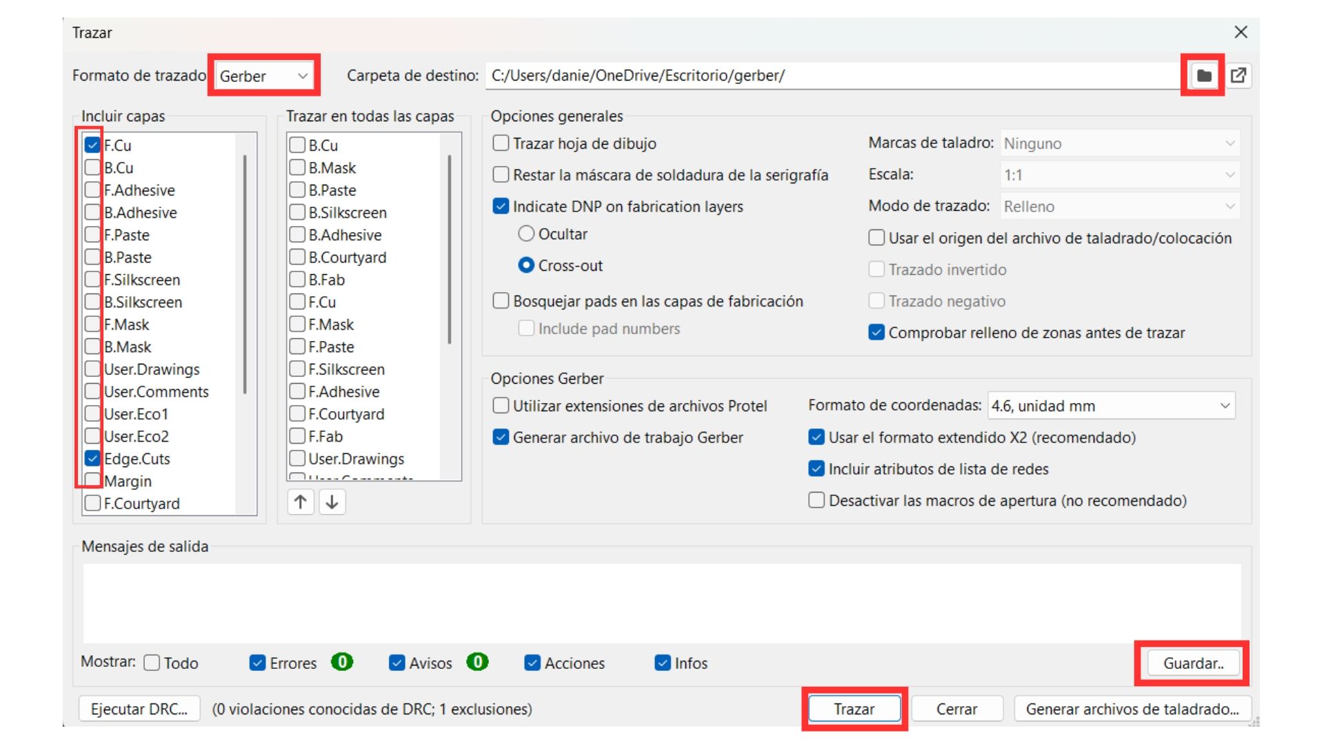
2. Convert to Gerber
Plot format: Gerber > Select the important layers (F. Cu and Edge. Cuts) > Select the correct folder > Plot > Save.
2. Gerber 2 PNG
The following video shows the complete process carried out in Gerber2PNG to convert our Gerber file into a PNG image, so these can be uploaded to the website to create the files for the MonoFab machine.
Complete process carried out in Gerber2PNG
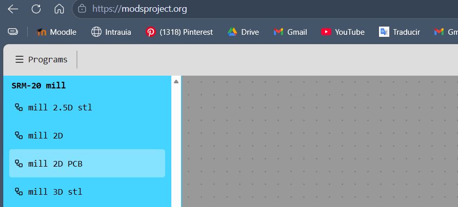
3. Modsproject.org
Process in Modsproject.org
b) Load PNG files
In the "red png" section, load our PNG files one by one.
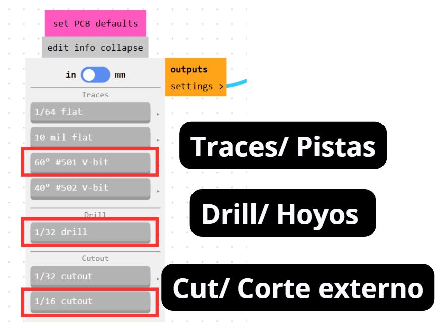
c) Configure the operation
This is not shown in the video because I forgot, but it is important to set the following values depending on the operation to be performed.
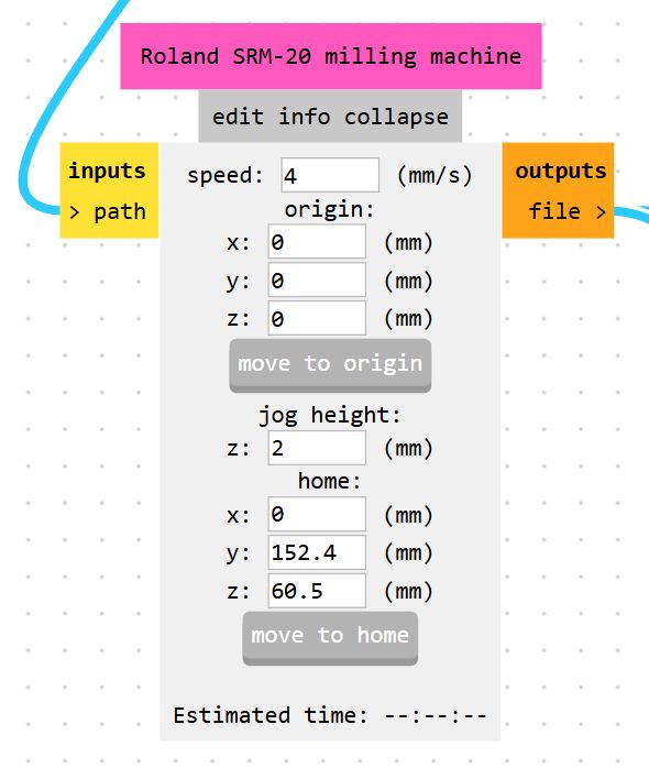
e) Roland SRM-20 milling machine
In the "Roland SRM-20 milling machine" section, set all origins to zero.
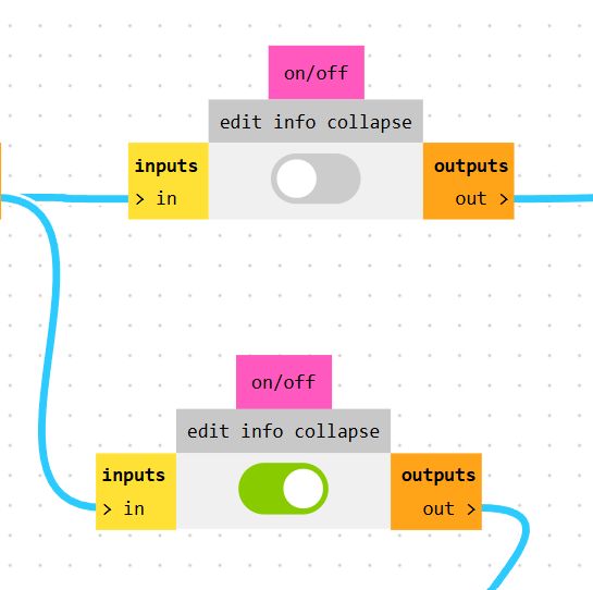
f) Activate the on/off section
Enable the on/off toggle below.
The following video shows the process followed for the trace section in the Software named Modsproject. Be careful though, as some steps were skipped in the video — they are all covered in the carousel above.
Trace process in Modsproject
The following video shows the process for the Cut. However, I forgot to set all origins to zero — that is shown in the video after this one.
Cut process in Modsproject
Setting the origins in Modsproject [step I forgot in the previous video]
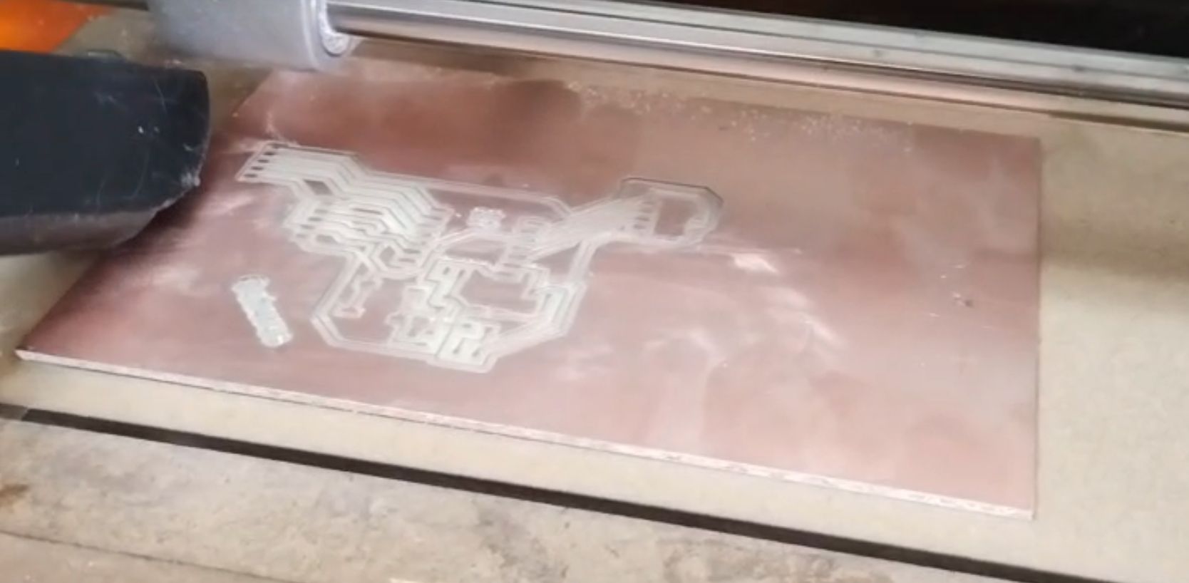
Cut
Preparing the copper board
First Step
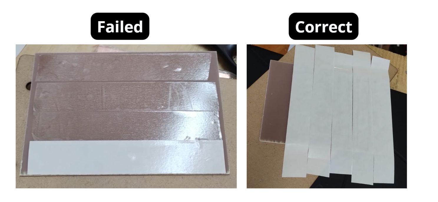
- First, apply double-sided tape to the back of the copper board.
Note: It must cover the entire board perfectly so it does not come loose while cutting.
Second Step
- Stick the board onto the sacrificial bed.
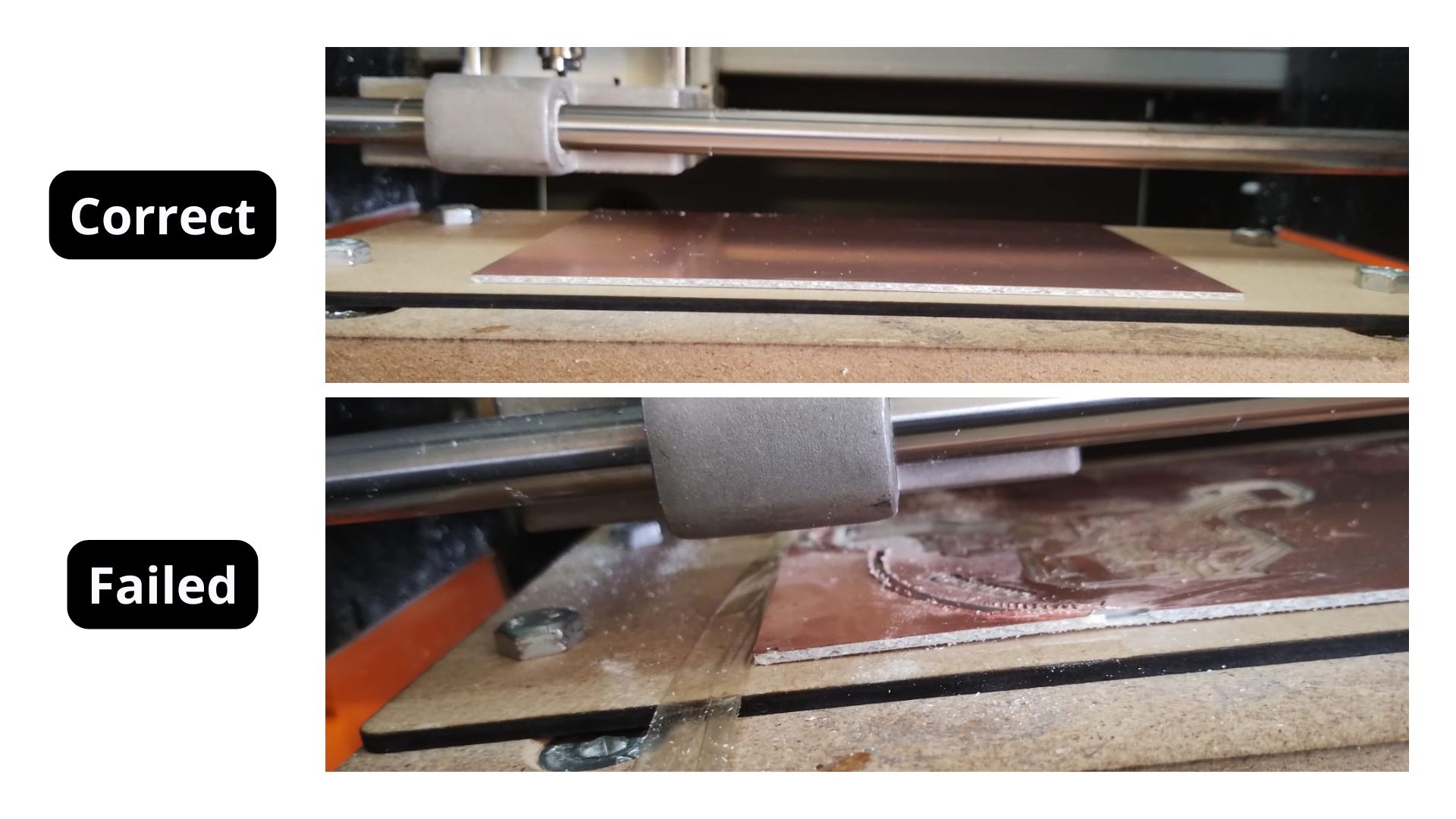
Mistake I made: Add extra tape on the sides where you are sure the board will not be cut, to prevent it from lifting. Halfway through the cut my board lifted and I had to pause. The board must be completely stuck to the sacrificial bed.
Third Step
- Screw the sacrificial bed into its mounting holes.
Fourth Step
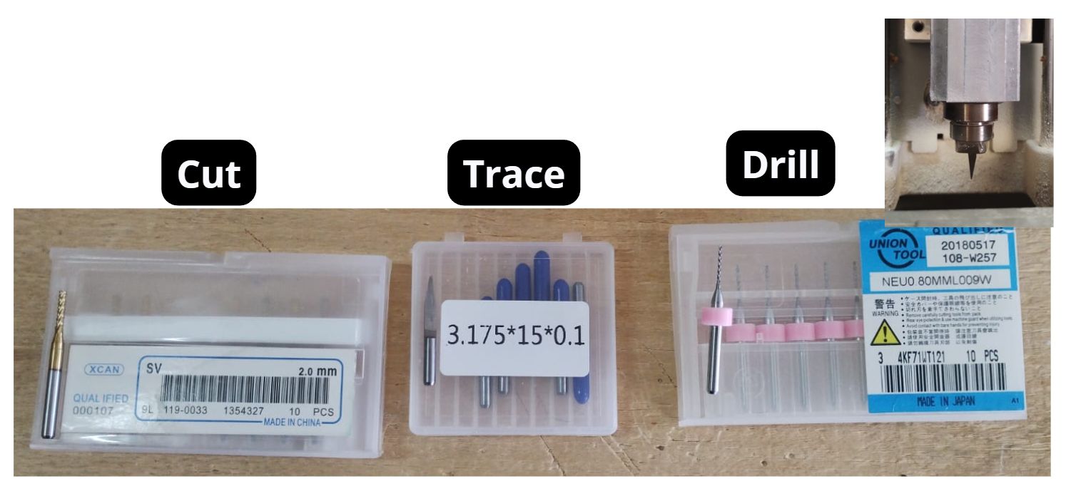
- Insert the bit into the collet. Depending on what you want to do, you must use the corresponding collet and tighten it with an Allen key.
Tool order:
- Drill
- Trace
- Cut
- Make sure the tool has enough sharpness.
- Do not insert the tool too deep.
- To loosen with the Allen key, turn counterclockwise; to tighten, turn clockwise.
4. V Panel SRM-20
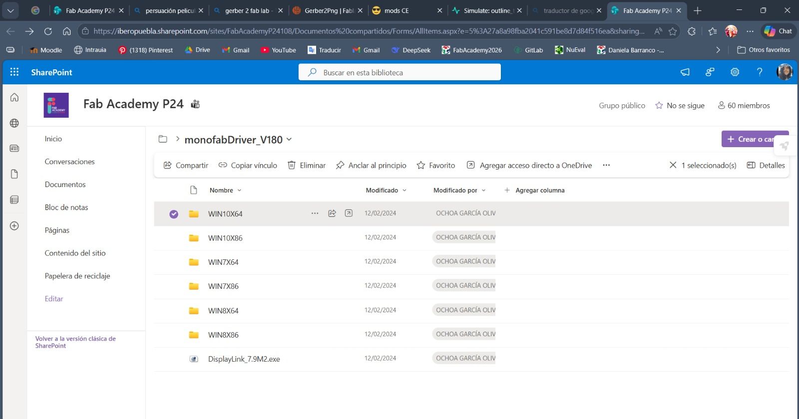
a) Download the software
From the link in the Software table at the top of this page, download the corresponding folder for your device. In my case, since I have Windows 11, I downloaded the first folder "WIN10X64".
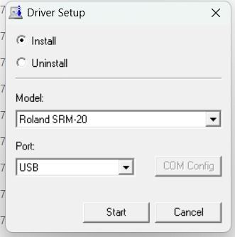
Run the file called "SETUP64.exe"
c) Configure the "X" and "Y" axes
Using the arrow keys, move to the bottom-left corner of the board. Once there, press the Origin button "XY".
Note: With Cursor Step you can tell the tool to move faster (the "Continue" option) or slower (the "x1" option).
d) Activate the Spindle and configure the Z axis
Using the tool in the bottom-left section of V Panel, under "Spindle", press the "ON" button so the tool starts spinning. This way, when it comes down to the board, it will not lose its edge.
Once satisfied with the Z axis position, lock the origin with "Set origin point" on the Z button. Then use the arrow keys to lift the tool up along Z and stop the rotation.
How do you know the Z axis is set correctly? It should be slightly deeper than the board surface, just enough to produce a small amount of dust, but not too much.
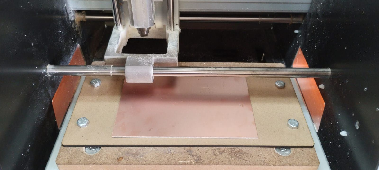
e) Cut
Using the cut button, find the file that corresponds to the tool being used and then select "Output".
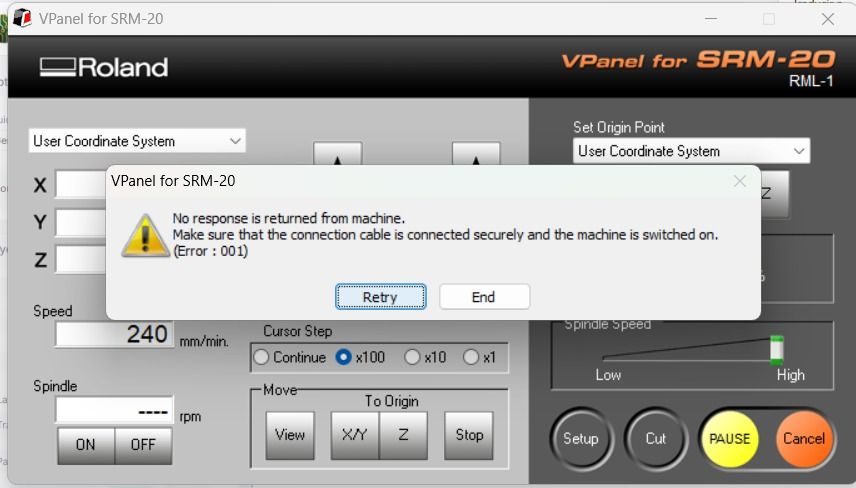
In case of emergency: If something goes wrong, press "Pause". If it can be fixed, correct the issue and resume. If not, press "Cancel".
Mistake I made: At one point the computer went into "Sleep" mode, and when I woke it back up a notification appeared. I clicked "Cancel" instead of "Retry", which closed the program along with my progress. The good news is that the program saves the previous origins, so I only had to restart the cut from where it left off.
Complete process in V Panel
f) Vacuum the dust
After each type of cut is finished, use a vacuum to remove the excess dust.
g) Remove the board
Then remove the board and sand the burrs on the edges so the board is left clean.
Solder and Program
Components
| Component | Description / Notes | KiCad Name |
|---|---|---|
| XIAO RP2040 | Main Controller (The Brain). 3.3V logic, sufficient GPIOs for the entire project. Includes internal regulator. | xiao |
| NEMA 17 | Bipolar Stepper Motors. Typically 12–24V, 1.5–2A per coil. Requires H-bridge driver with microstepping. | Pines de 4 |
| H-Bridge TB6612 | Motor Drivers. Allows DC motors to rotate in both directions and functions as a brake. | Tb 67 |
| LED | Red/Green Indicators. Provides visual signals for power status and H-bridge operational state. | 1206 |
| LED Resistor | Current Limiting. Prevents the LEDs from burning out. Value: 1kΩ. | 1206 |
| Buttons | User Input. Tactile switches used to activate the H-bridges and control stepper motors. | Tac / Switch_Tactile_CnK |
| Pull-up Resistor | Logic Stability. 10kΩ pull-up resistor for the button inputs. | 1206 |
| Motor Connector | Output Port. 4-pin connection point for the stepper motors. | Pines 4 |
| Power Connector | Main Input. 2-pin entry point for Voltage and Ground power supply. | Pines 2 |
| Decoupling Cap (Driver) | Noise Reduction. Absorbs electrical noise to stabilize high-frequency signals. Value: 100nF. | 1206 |
| Bulk Cap (Driver) | Voltage Stabilization. Prevents voltage drops during motor startup. Value: 47–100µF. | Electrolytic |
| Decoupling Cap (XIAO) | Frequency Filtering. Prevents microcontroller resets due to electrical interference. Value: 100nF. | 1206 |
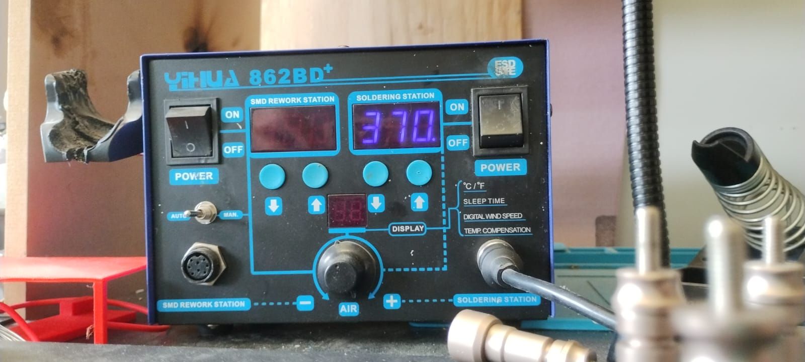
Soldering
To solder, I first turned on the machine to a temperature between 360°–370° (which is the ideal range).
I then started by soldering the smallest components, which in my case were the resistors, LEDs, and the capacitor.
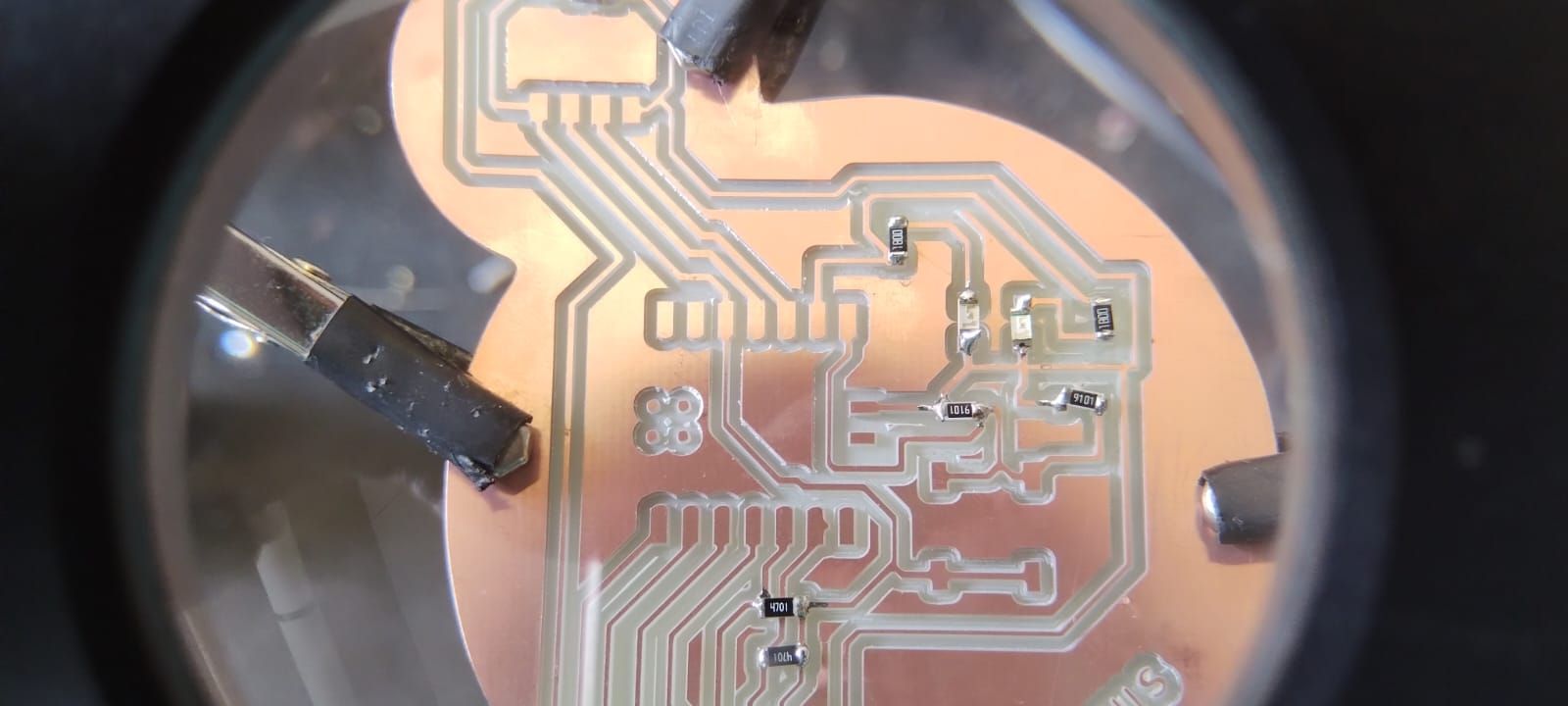
How to solder?
I found it much easier to place the soldering iron on the component and the board for about three seconds, then bring the solder with flux (the substance inside that melts) as close as possible to the tip of the iron, so the solder does not stick to the iron's tip instead of where I want it.
I then soldered the XIAO RP2350, as it was the next largest and most cumbersome component. Finally, I added the pin headers, since they were the largest and therefore the most obstructive. The board then looked like this.
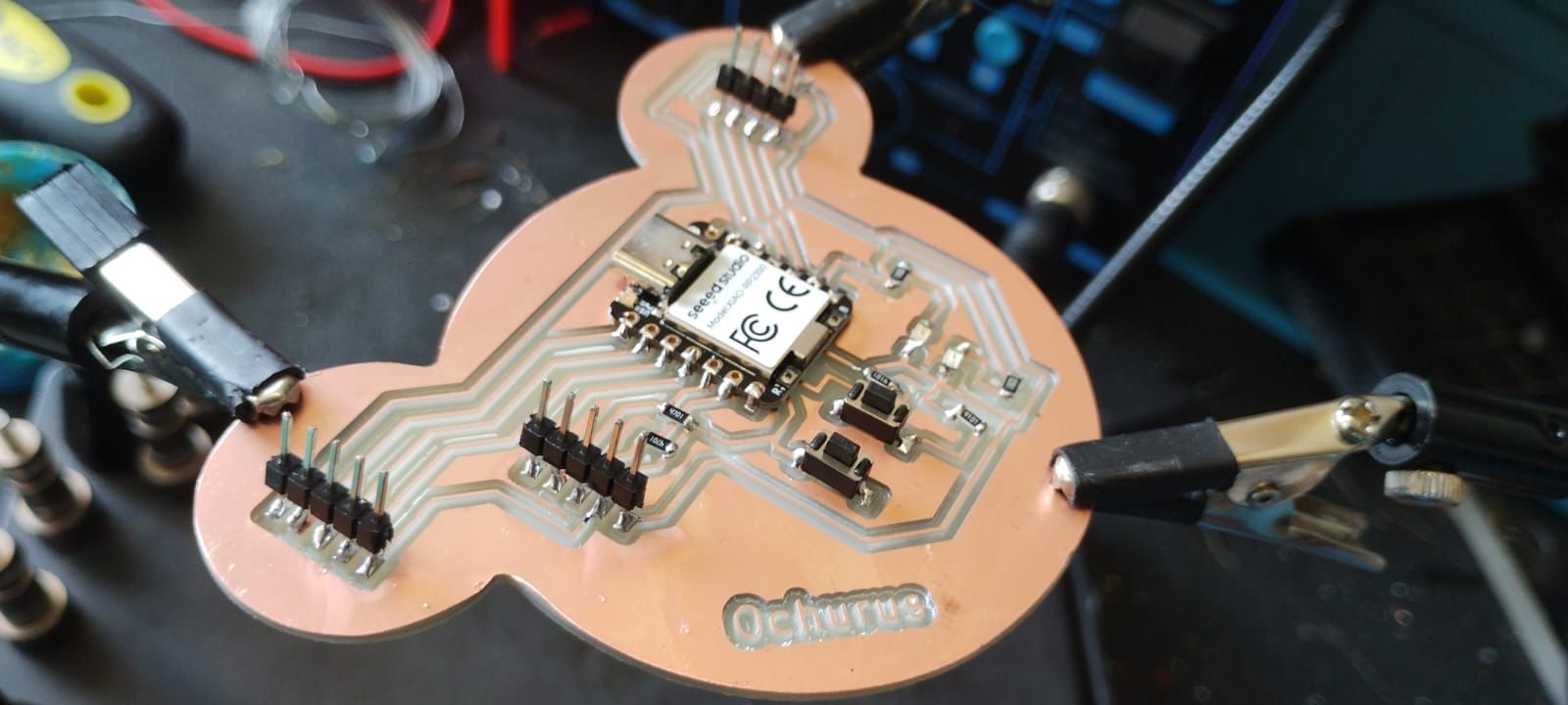
In the following video, I show how I tested the board to ensure it was properly connected and that there were no potential short circuits.
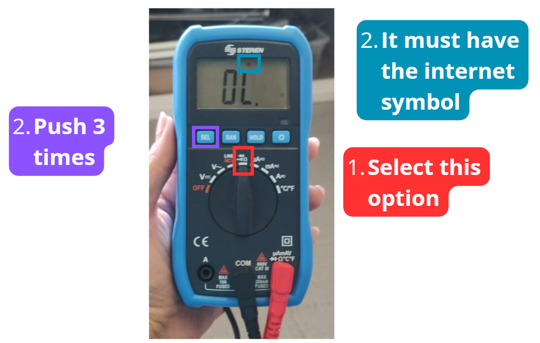
The method I used was: when touching both multimeter probes together, it beeps, indicating that the parts are connected; if it doesn't beep, there is no connection (continuity).
Testing the board
This is how the multimeter should look:
Installing the XIAO RP2350 in Arduino IDE
To get Arduino IDE to recognize the XIAO RP2350, I asked Claude AI for help with the procedure to install the corresponding "Boards Manager".
The prompt I gave to Claude was the following:
Prompt: "I'm about to upload the code, but first I want you to help me understand how to send code to my XIAO RP2350 from the Arduino IDE interface. The board is connected to my computer via a USB-C cable."
The code it provided, which is shown in the video, is the following:
https://github.com/earlephilhower/arduino-pico/releases/download/global/package_rp2040_index.jsonAll the steps I followed are shown in the video below:
Programming
To get the code for the board, I uploaded a photo of my board in the KiCad Editor to Claude and gave it the following prompt explaining my problem.
Prompt: "Hi! The photo I'm attaching is of a PCB I'm making with a XIAO RP2040. I want you to help me write the code so that one of the buttons turns on one of the LEDs, and the other button turns on the other LED when pressed.
Please make the LEDs stay on once you press the button, and turn off when you press the button again — not just stay on while the button is held down."
The code it gave me was:
// ================================
// PCB Ochurus - XIAO RP2350
// Toggle + Parpadeo de LEDs
// ================================
// --- Pines ---
const int LED = D8;
const int BTN = D7;
// --- Variables de estado ---
bool ledActive = false;
bool lastBtnState = LOW; // ← Cambiado a LOW (pull-down = LOW en reposo)
// --- Temporización del parpadeo ---
unsigned long lastBlink = 0;
const int blinkInterval = 500;
bool blinkState = false;
void setup() {
pinMode(LED, OUTPUT);
pinMode(BTN, INPUT_PULLDOWN); // ← Cambiado a PULLDOWN
digitalWrite(LED, LOW);
}
void loop() {
bool currentBtnState = digitalRead(BTN);
// Detecta flanco de subida (cuando se PRESIONA con pull-down)
if (lastBtnState == LOW && currentBtnState == HIGH) { // ← Invertido
ledActive = !ledActive;
if (!ledActive) {
digitalWrite(LED, LOW);
}
delay(50); // Debounce
}
lastBtnState = currentBtnState;
// Parpadeo sin usar delay()
if (ledActive) {
unsigned long now = millis();
if (now - lastBlink >= blinkInterval) {
blinkState = !blinkState;
digitalWrite(LED, blinkState);
lastBlink = now;
}
}
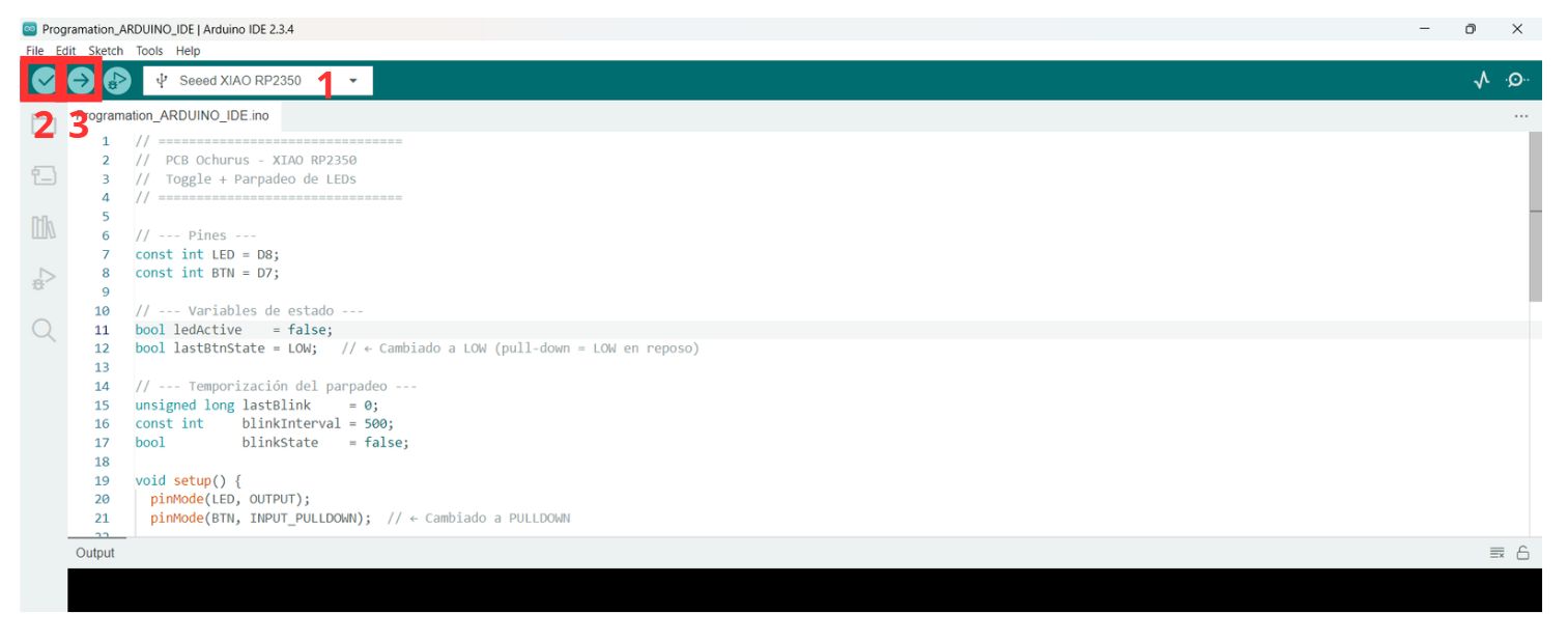
}Once I had the code, I connected the XIAO to my computer with a USB-C cable, then:
- Select the correct port.
- Once I had the code, I connected the XIAO to my computer with a USB-C cable.
- I clicked "Verify".
- Select "Upload".
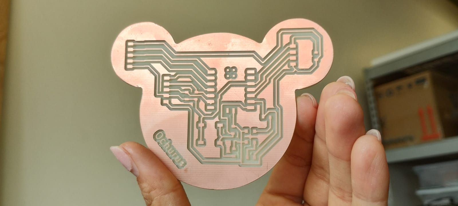
This is how the board looks in the end:
If you're Gen Z, you know the OCHURUS reference! 🐭
What I learned this week:
- I learned the full PCB fabrication workflow: exporting Gerbers from KiCad → converting to PNG with Gerber2PNG → generating RML files with Modsproject → cutting on the MonoFab SRM-20 with VPanel.
- I discovered that double-sided tape must cover the entire copper board without gaps to prevent it from lifting mid-cut, and that adding extra tape at the edges is a vital preventive measure.
- I learned to solder SMD components starting with the smallest (resistors, LEDs, capacitors), then the XIAO RP2350, and finally the pin headers, verifying circuit continuity with a multimeter before programming.
What I learned from the group page:
- I learned the technical differences between the Roland SRM-20 (mechanical milling) and the xTool F1 Ultra (fiber and diode laser engraving), including compatible materials, typical parameters, and specific workflows in Mods and xTool Studio.
- I understood how to upload a PCB design to a manufacturing house (JLCPCB): compressing Gerber files, uploading them to the platform, reviewing the preview, customizing parameters, and tracking production.
- I learned to identify the minimum resolution of the SRM-20 using Neil's test file: with a 0.1 mm bit and a cut depth of 0.1016 mm, traces of approximately 1–5 mil can be achieved.
Files I used this week
01_KICAD_FILES.ZIP
KiCad Project Files
Files:
- fp-info-cache
- PLACA MODIFICADA.kicad_pcb
- PLACA MODIFICADA.kicad_prl
- PLACA MODIFICADA.kicad_pro
- PLACA MODIFICADA.kicad_sch
- PLACA MODIFICADA_Step
02_GERBER.ZIP
Gerber Manufacturing Files
Files:
- PLACA MODIFICADA-Edge_Cuts.gbr
- PLACA MODIFICADA-F_Cu.gbr
- PLACA MODIFICADA-job.gbrjob
- PLACA MODIFICADA-NPTH.drl
- PLACA MODIFICADA-NPTH-drl_map
- PLACA MODIFICADA-PTH.drl
- PLACA MODIFICADA-PTH-drl_map
03_MODSPROJECTS.ZIP
Mods Production Files (RML)
Files:
- outline_top_layer_1.png (3).rml
- traces_top_layer_0.png.rml