Output Devices
Similar to input devices, output devices refer to any type of device meant to “export” information from the micro-controller to the outside world. If we look at it like a sequence of events, input devices are first, then the micro-controller processes the received information, and finally the output device reacts upon it.
Output devices can be as simple as LED or as complex as a series of motos that must act in a very specific and time sensitive manner. Like with input devices, there are a lot of types of output devices, al tailored to any type of project you can have in mind. Some examples of output devices include:
- Motors.
- Screens.
- Speakers.
- Lights.
For more information on output devices and how to properly use them, check out our Lab’s group assignment page. From my group assignment I learned that the most important thing to consider when using any output device is the power source (hence why this week is commonly referred to as the "Power week" in our Lab). It is important to consider the voltage requirements of each individual device, plus its combined amperage. A single servo motor can work properly when connected to a micro-controller, but several servos connected to the same micro-controller will require too much amperage to function, putting the micto-controller at risk of being burnt. All of these considerations help us create a project that is not only stable, but also safe for its components.
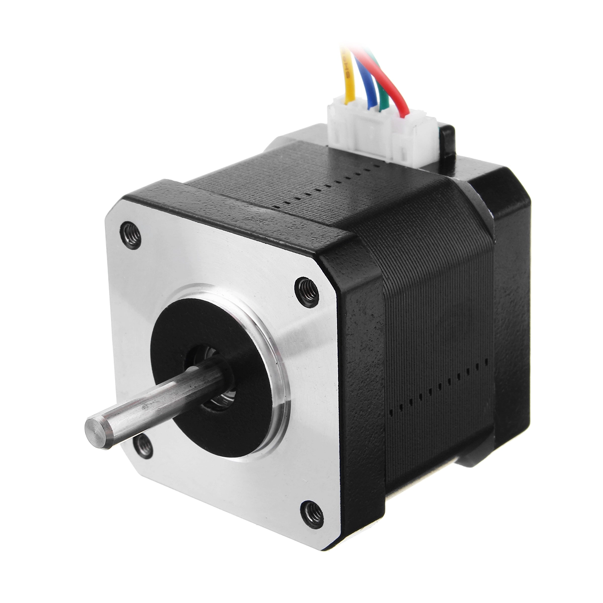
The Stepper Motor
For my final project I need a 360 degrees rotating base. This base can be built in various ways, but most requiere a basic component to work: a stepper motor.
As its name implies, a stepper motor is a motor that works by rotating in a small angular step. Unlike servo motors, where powering the motor makes it move, stepper motors require to know exactly how many steps to take in order to move. Servo motors are better used for applications where speed and torque are a must, stepper motors are better used for applications where precision and a full rotation range are a must. For our rotating base, a stepper motor will work.
Using a Stepper Motor
Using a steppe motor is not as straight forward as using a servo motor. Unlike a servo motor where you just “plug and play”, a stepper motor require some extra hardware to correctly operarte. We need a way of telling the stepper motor how many steps to take on which direction, and for that we need a Driver. A driver is a chip that converts digital signals into electrical pulses. In simple terms, is a translation between our micro-controller language and our stepper motor language.
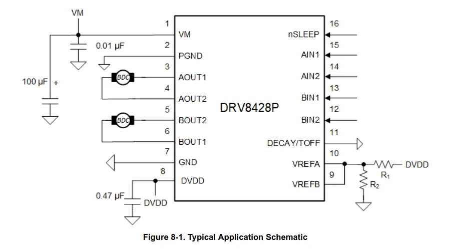
For our driver we will be using a drv8428, mostly because it is the available chip in our University. Using this chip is also not as easy, as it requires extra components to work correctly. This is a good thing however, as it gives us the opportunity to design its module directly into our PCB, without depending on a pre-built module design.
Taking a look at the drv8428 datasheet, we can see a typical use schematic, which we will be implementing into our custom PCB.
We can now take this schematic and replicate it in our new KiCad project. Doing it is quite simple, as the symbol for the drv8428 is available on our FAB library. It only took a couple of minutes, and the schematic was ready!
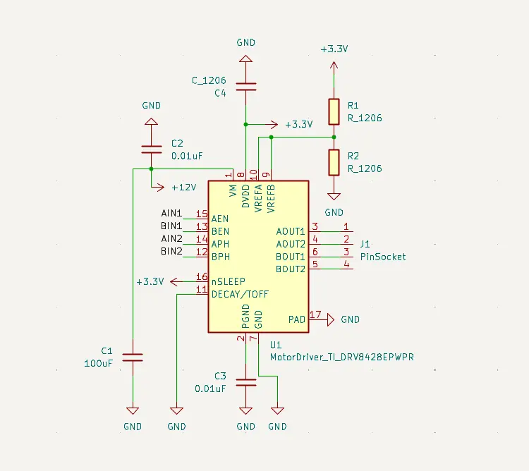
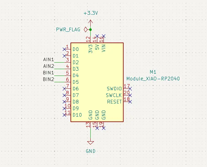
Now, as we will be using out RP2350 for this project as well, we must design the needed connections.
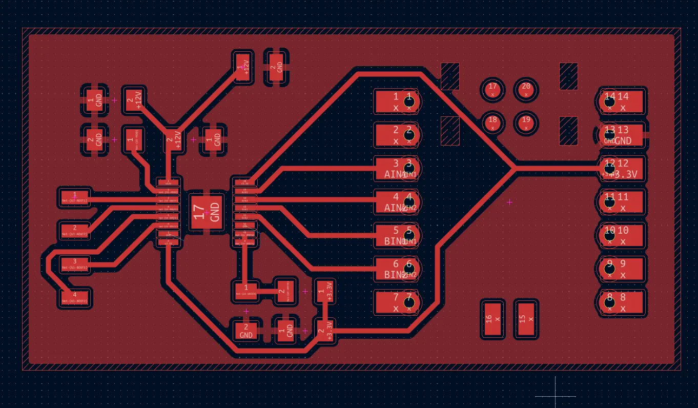
And with that, we are ready to design the PCB. Similarly to the previous week’s PCB, this one was also quite small, as it has the bare minimum components needed to operate our servo motor.
With the PCB, is now time to engrave and cut our PCB.
Producing the PCB
This time, I tried to make the edge cut in our Roland milling machine and then engraving in the XTool. But for whatever reason, the edge cut in the Roland kept being cut smaller that needed. I don’t know if this is a problem with the mods project configuration, or if I’m doing a step wrong when choosing my edge cut image. I decided to solve this problem later on, and stick with the previous XTool engrave and band saw cut workflow.
Engraving the PCB was pretty straight forward, as my previous experimenting with the different parameters of the XTool gave me the perfect values which I just need to plug and send. It took some time, but in the end I got a high quality PCB in my hands. Plus, this week requires the use of the drv8428 chip, which has very small legs and, therefore, small tracks. I’m sure the Roland would have had trouble with this small tracks.
Note: Everything below this point will be made using a DRV8825 module and a new PCB. The DRV8428 chip wasn’t available in our lab, unlike the DRV8825 module. The idea was for us to learn how to create our own driver modules starting with just the chip and then adding every component needed for its operation. Considering that the chip wasn’t available in our lab and getting it imported would take a lot of time, we where authorized to use the model.
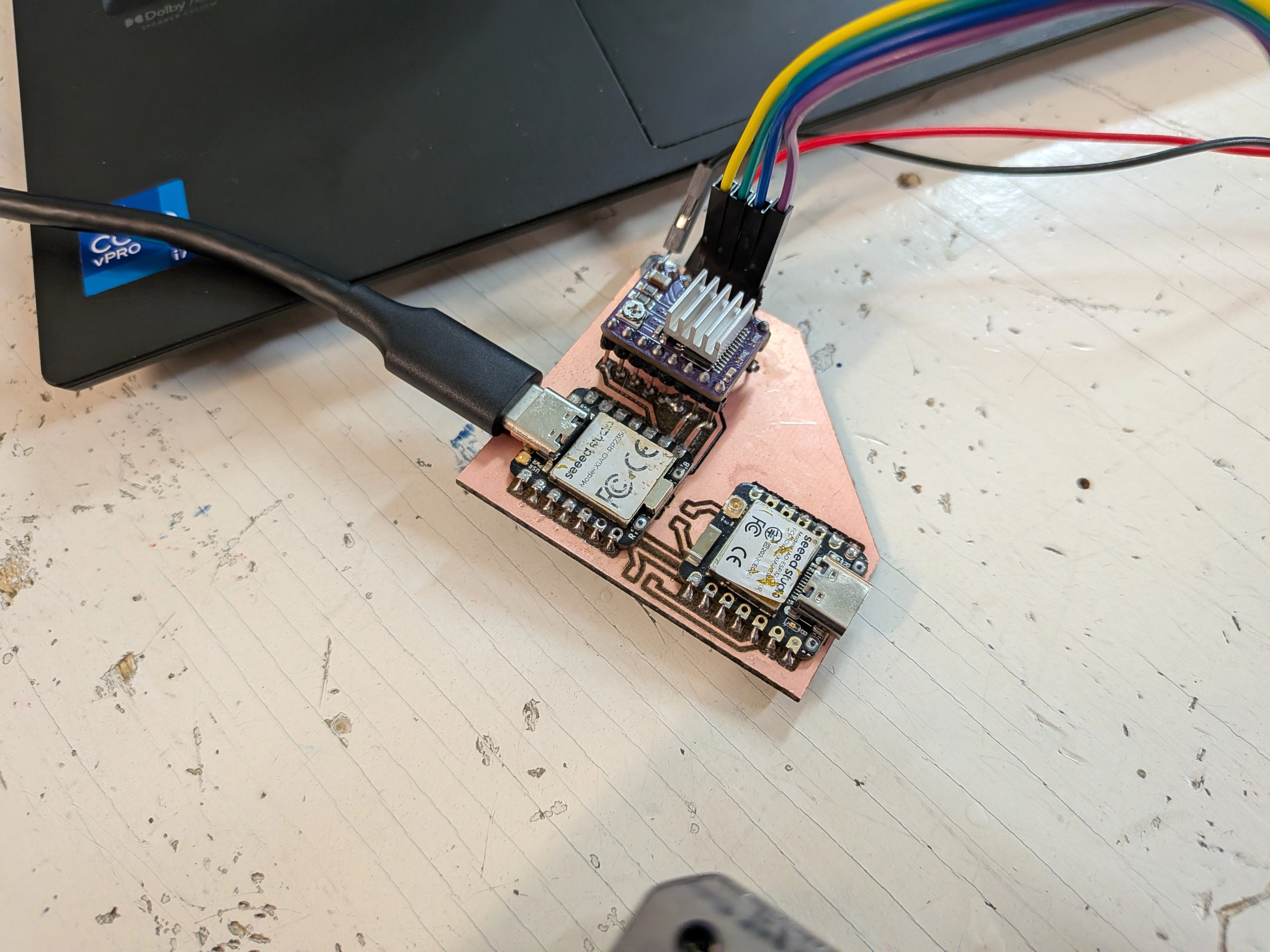
The resulting PCB, with the drv8825 module turned up looking like this:
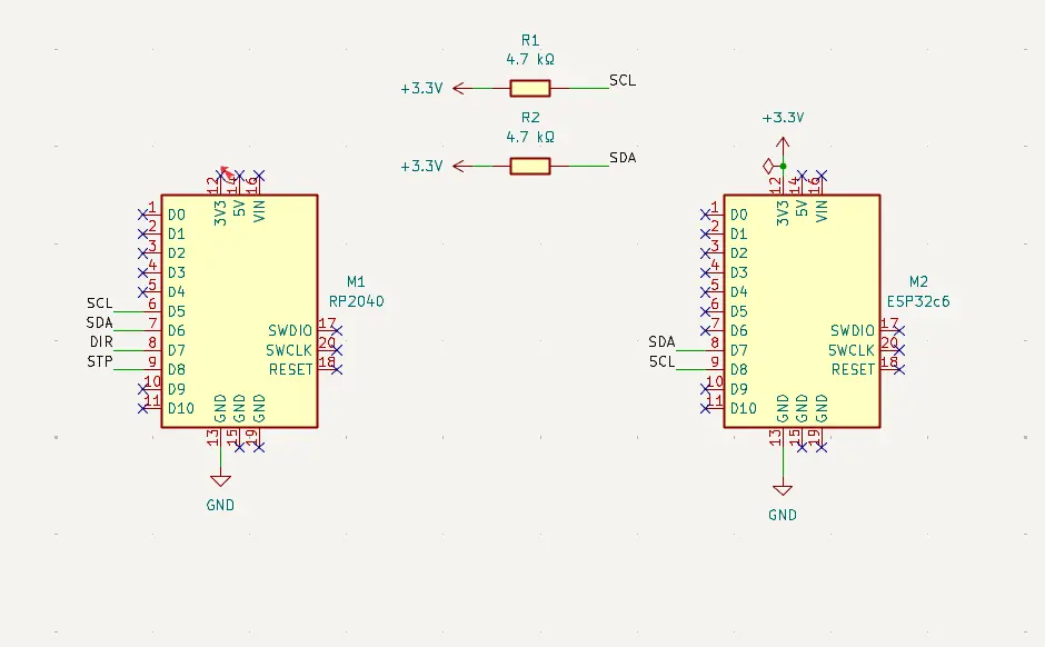
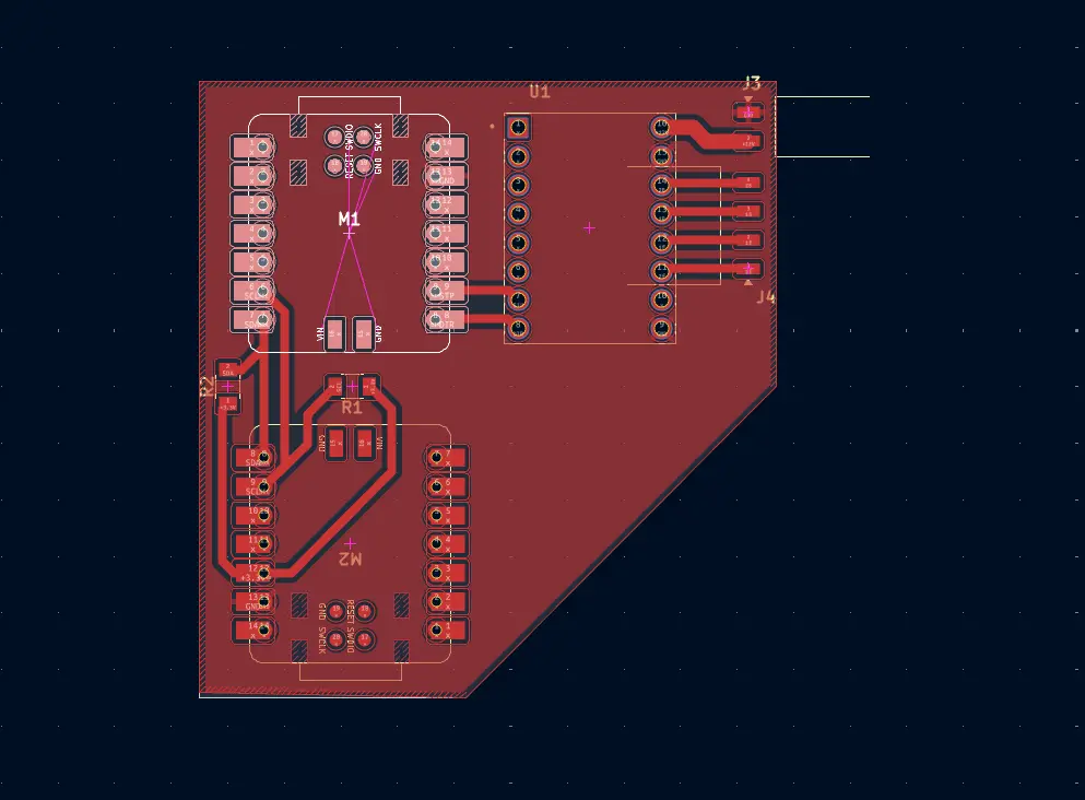
As you can see, there are two micro-controllers placed on the PCB. The reason for this is to use the same PCB for both this week and next week’s assignment, the Networking and Communication week. The reason for this decision was to multitask, as here in Mexico Holly Week just happened, which meant we all went on vacation for a hole week. To reduce the time I would need to design and produce two separate PCBs for each week, I designed this PCB. For now, we will only be focusing on the RP2350 and DRV8825 moudle. Next week, we will be implementing the other micro-controller and its communication connections to this RP2350. Check out my Week 11 assignment page to see that part of the PCB in action.
Using the Driver
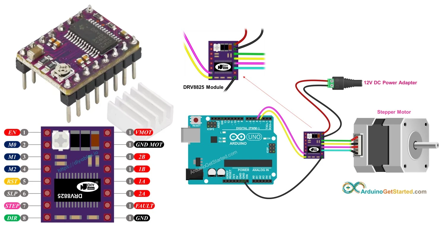
The DRV8825 module includes 16 pins, 4 of which are for connecting the stepper motor and 3 are for power and ground. The rest of the pins have very specific use cases, but in reality we only need two: DIR and STEP. The STEP pin controls the amount of “steps” the motor will take, and the DIR pin will control the direction of the movement. Another useful pin can be EN, which turns the motor on and off. All of this pins must be connected to any GPIO pin in our micro-controller.
Connecting the module is quite straight forward. The module requires a 12v power supply to work properly, plus every other connection mentioned before. You can follow this diagram for the most basic required connection. The example uses an Arduino UNO board, but our Xiao RP2350 will work exactly the same.
Now, everything relies on the programming of the micro-controller.
Programming the Stepper Motor
Programming our stepper motor logic is also quite easy. We just need to tell the stepper motor how to “step” and how many times to do it. In micropython, the “step” logic is as simple as sending a High and then a Low value to the STEP pin. Then, the we just tell it to do it n amount of times. For the direction, a High value will be a clockwise turn, and a Low value will be an anti clockwise turn, all in the DIR pin.
Here’s a code example in mycropython:
from machine import Pin
import utime

STEP = Pin(5, Pin.OUT)
DIR = Pin(4, Pin.OUT)

def move_motor(steps, direction, speed=0.001):
	DIR.value(direction)

	for _ in range(steps):
		STEP.value(1)
		utime.sleep(speed)

		STEP.value(0)
		utime.sleep(speed)

while True:
	move_motor(steps=200, direction=1, speed=0.002)
	utime.sleep(1)

	move_motor(steps=200, direction=0, speed=0.005)
	utime.sleep(1)
This code is really easy to understand. Dir.value(direction) tells the motor on what direction to move (clockwise or anticlockwise). The for loop is there to send the "Stepping" signal once for every step we want to take. And the utime.sleep(speed) controls the time between steps, preventing the motor from jamming itself trying to constantly take steps. Mycropython makes it easier to understand, but the idea of this code is the exact same for Arduino or C. Even better, the idea for (almost) every movement you can think of with a stepper motor is the same: tell it how many steps to take in what direction.
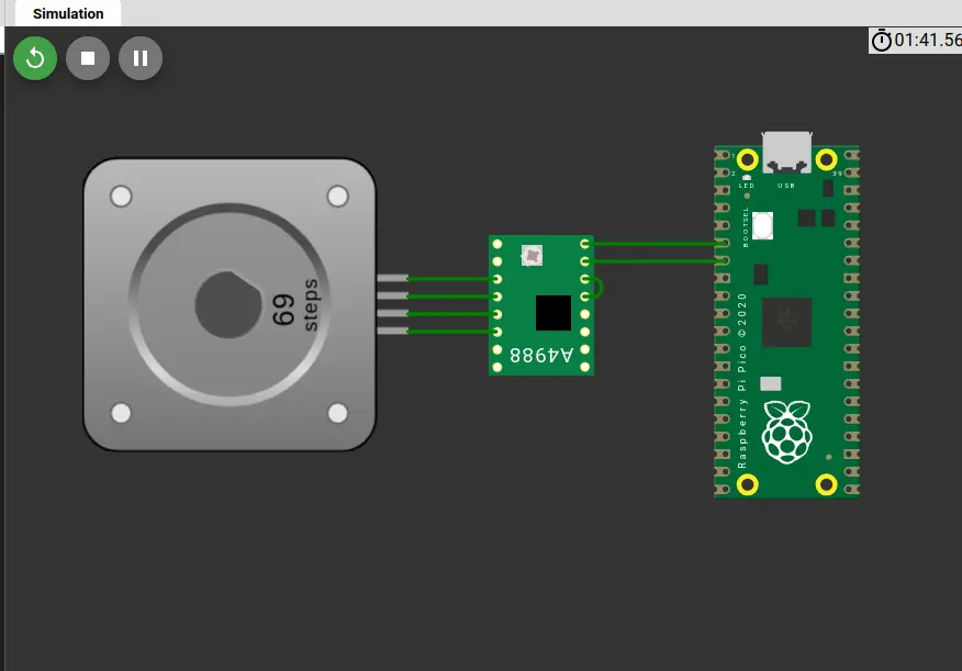
Wokwi serves, again, as a great playground to test the capabilities of our stepper motor. Running the previous script on Wokwi, with the following setup, results in a perfect movement. Like with every skill learned in this FAB Academy, exploring and experimenting are key.
Testing on a PCB
As explained above, the PCB of this week will also be shared with next week‘s assignment, the Networking and communications week. For this test, will only need the RP2350 mounted on the PCB with its corresponding connections for the stepper motor.
However, when running my script that controls the stepper motor, it did not move. I tried troubleshooting it, changing the VRef resistance value on the drv8825 module (the little screw), but nothing. The power source I was used showed me 0 amps, meaning there was no power draw comming from the motor.
After some investigating I came out with some possible reasons as to why my motor wasn’t running properly:
- The Rest and Sleep pins on the drv8825 need to be connected to one another, receiving an activation signal of 3.3v, comming from the RP2350 itself.
- The Enable pin on the drv8825 wasn’t connected to the RP2350, which is recommended for proper functioning of the stepper motor.
I could have used jumper wires to do the needed corrections, but on the spirit of learning and doing things right, I decided to redo my PCB. During this PCB redo, I was actually able to trace AND cut the PCB edge in the XTool!
After producing the new PCB and soldering everything needed, I connected the stepper motor and the power source. And after some adjusting of the VRef value, ending with a 0.5V value on it, I sent the scrip to the RP2350 and the stepper motor started to move!