Networking Devices
To this point, we have done all of our work in a single micro-controller. For most projects a single micro-controller is ideal, as it keeps things simple and cost effective. If our small but powerful Xiao RP2040 (or RP2350) is not enough, you can always use an ESP32 board with more computing power and pins to work with. You can even use the ESP32 chip itself for a more professional and optimized application. But what if our project demands using two distinct micro-controllers? What if our project requires some sort of communication between the micro-controllers?
Networking refers to the various methods of communications between devices, ranging from physical wired connections to Wi-Fi and Bluetooth connections. Some examples of networking methods include:
- I2C
- Wi-Fi HTTP
- Wi-Fi MQTT
- ESP-NOW
- BLE (Bluetooth Low Energy)
For more information on how this protocols work and examples on how to use them, you can check our Lab’s group assignment page. From this assigment I learned the basic functionalities and applications of the main networking protocols. We were able to see all of this protocols in real life scenarios, plus getting example code for each. For my week work, I’ll be testing I2C and Wi-Fi HTTP, as they are the protocols I’m most likely to use for my project.
I2C
I2C (Inter Integrated Circuit) is a serial communication bus meant to connect low-speed embedded peripherals and ICs. I2C is king when needing to share information between two micro-controllers that are close to each other. I2C works with main and support modules. The Main module controls the other support modules, sending instructions and receiving data from sensors, for example. In my Final Project Page you can see that my idea is to connect a Raspberry Pi 5 and an ESP32s3. Whilst this connection can be made with an USB connection, I2C can also be an alternative.
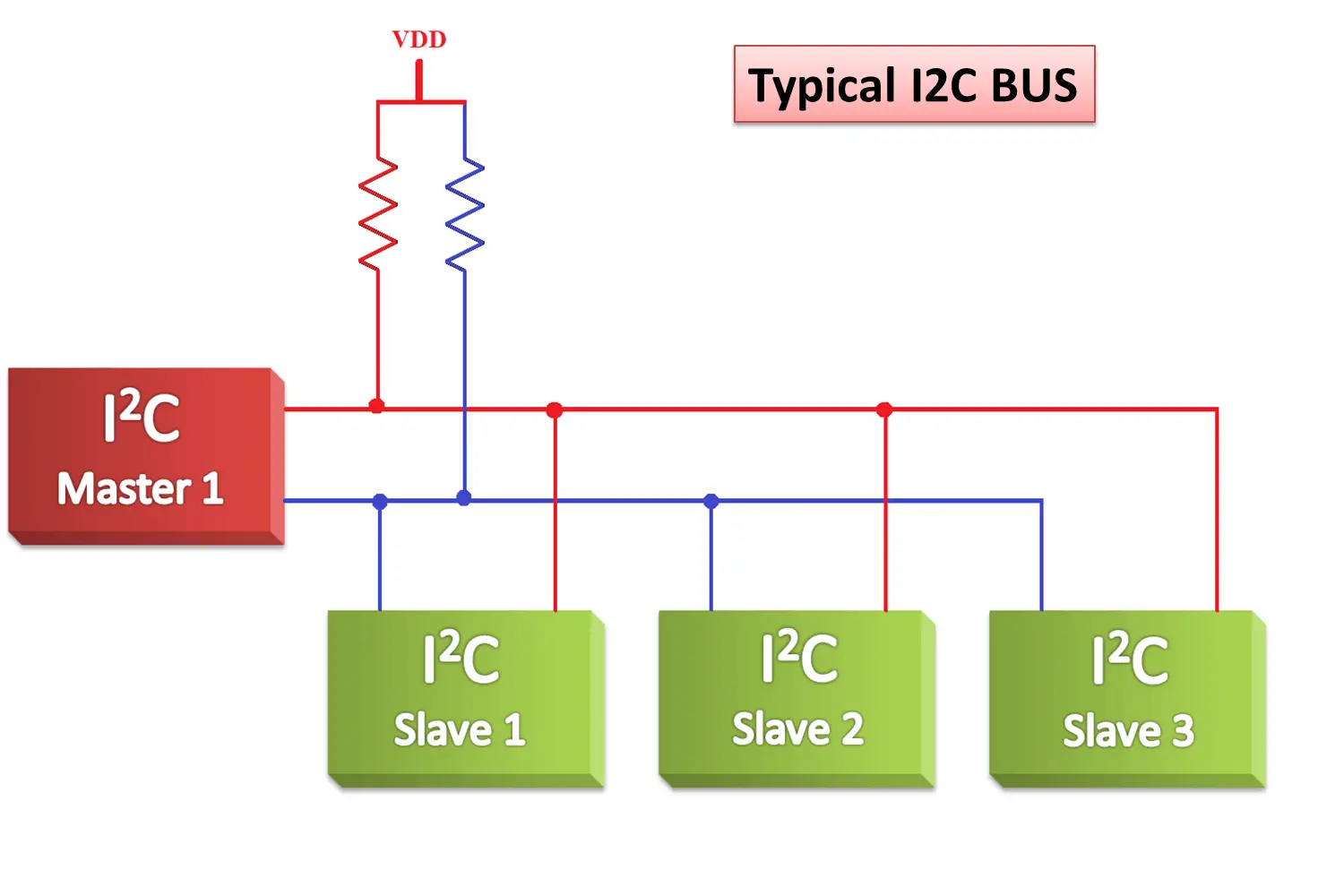
Note: The “Master and Slave” naming is now outdated. “Master” is now “Main”, and “Slave” is now “Support”.
In this diagram, the Main and Support ICs are connected by two tracks called STL and SDA. This tracks are connected between the Main module and the Supporting modules. There is also a pair of pull-up resistors, usually of 4.7 kOhms, that must be connected between the SDA / STL track and a 3.3v power source, usually coming out of the Main micro-controller. With this done, our physical connection of I2C is ready!
I2C Real Application
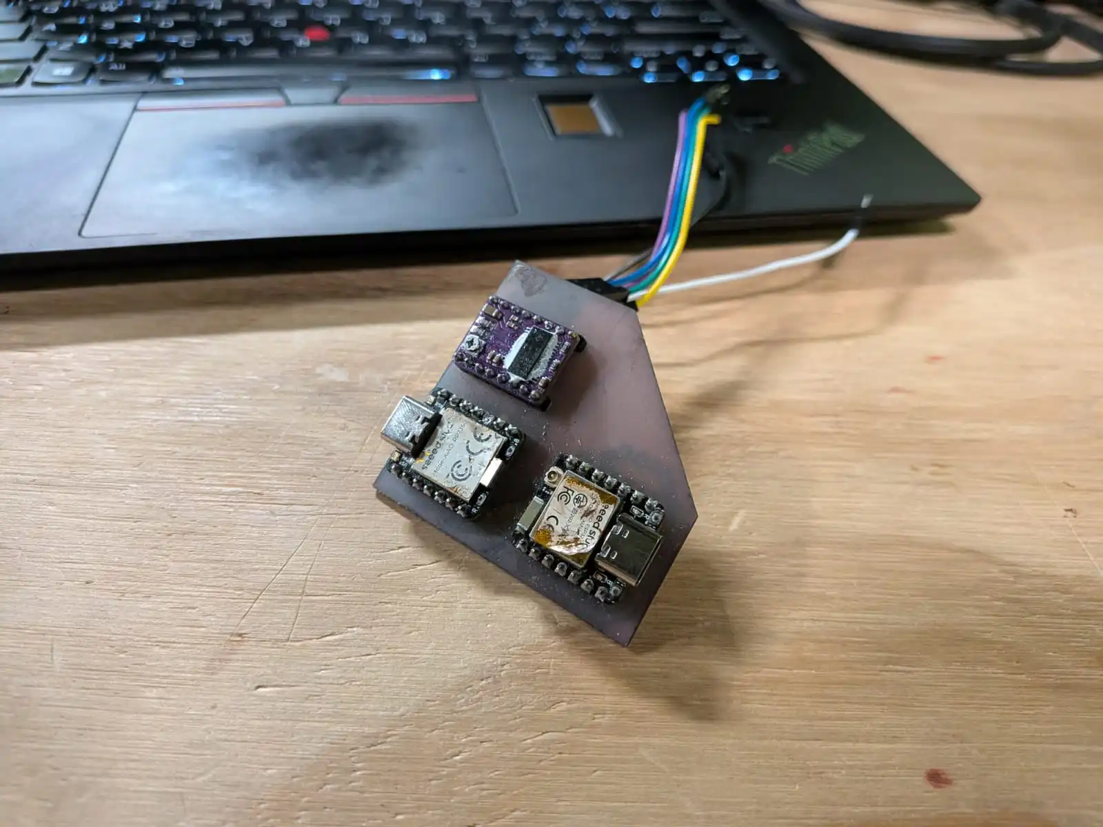
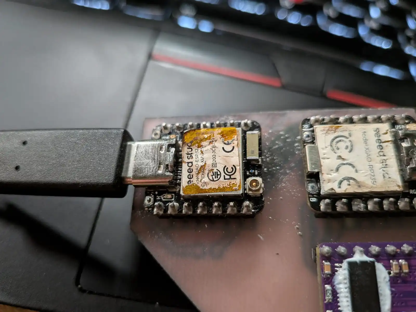
We will be designing a PCB to connect a Xiao RP2350 and a Xiao ESP32c6 with Wi-Fi capabilities (more on that later). For this, we’ll be using the previous week’s PCB with some modifications:
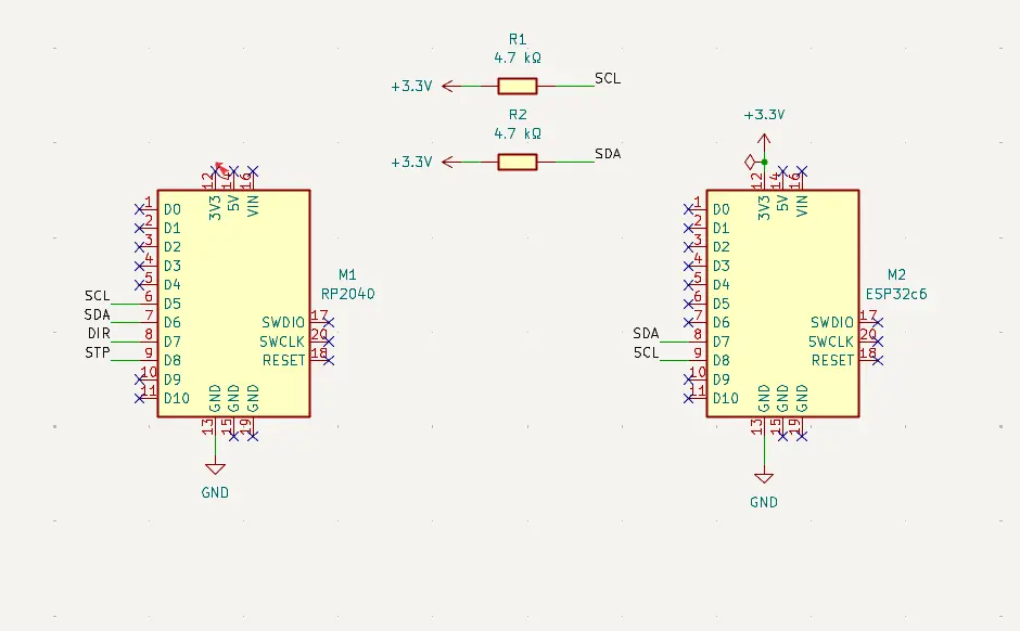
Firstly, we added the ESP32c6 to the board and the pull-up resistors:
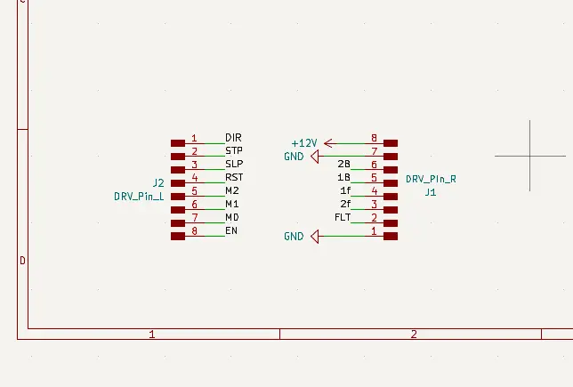
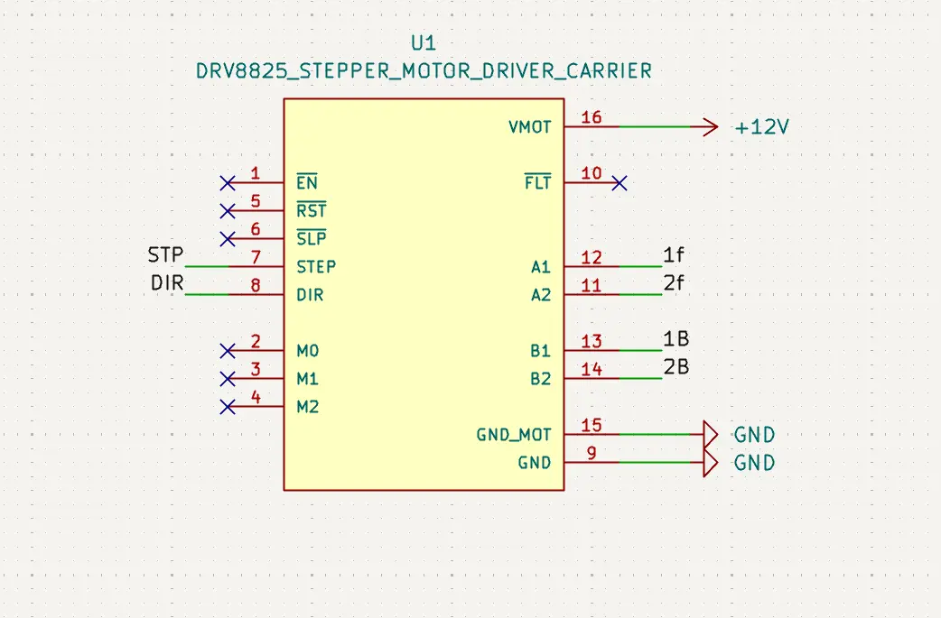
Now, we must update our driver for the stepper motor. The original idea included the use of a drv8428 chip with the necessary supporting components for it to work. Sadly, the chip didn’t arrive on time to our Lab, so we have to use the alternative: a drv8825 module. The module itself works similar to the drv8428 chip, but with everything already placed to work out the box.
The problem with using this module is adding it into our PCB, as it comes pins that we can either de-solder or place trough-hole our PCB. This means that getting the size of the module PCB right is a must. I first tried to make it by hand.
But getting the placement on the PCB was going to be an issue. So, I went to google and found both the symbol and footprint of the module in SnapEDA. Adding this symbol and footprint into my KiCAD solved my main issue with this PCB.
Now, we just finish our PCB in the PCB editor:
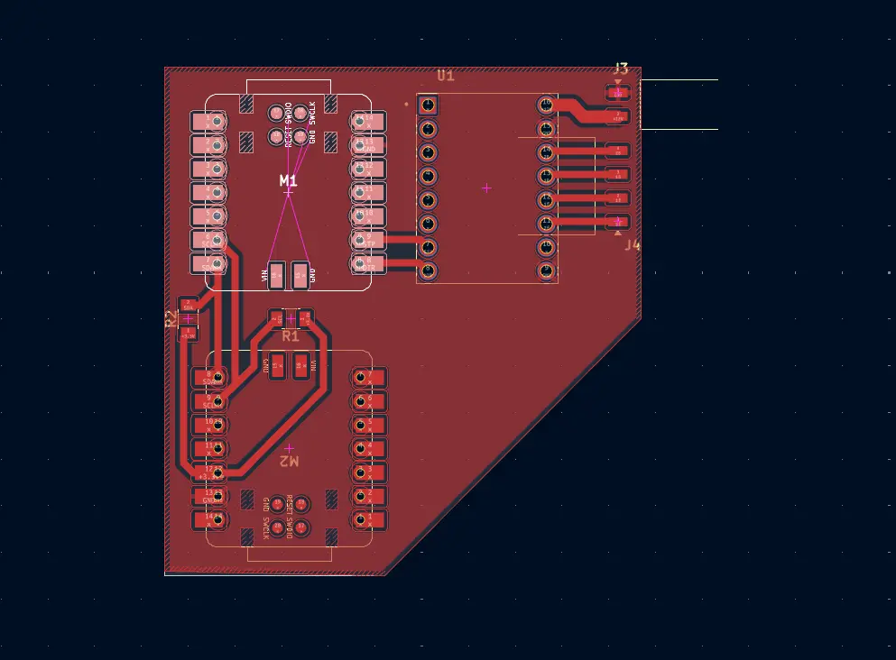
Note: The floating yellow lines out the top right corner of the PCB are not a mistake. The lines itself do not affect the overall shape and tracks of the PCB.
Now we just need to produce our PCB and we’ll be ready to go!
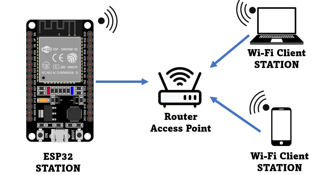
Wi-Fi
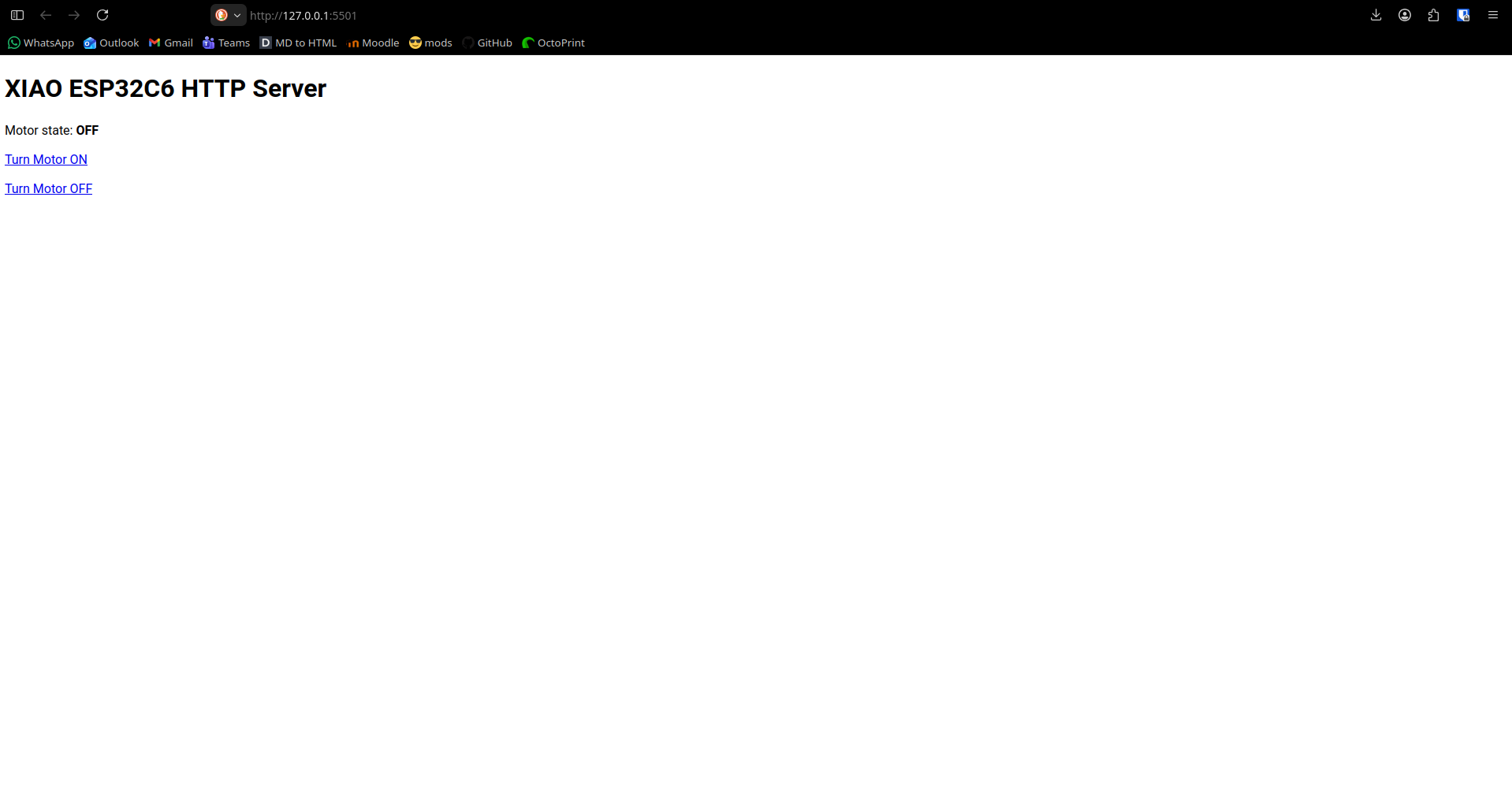
Before moving on with physical testing, there is another networking method I wanted to test. The Wi-Fi method consists on hosting a web page on your local network, where you can send signals through routes. Routes are basically all the places you can go in a web page and that make its structure. For instance, the main route of any page is “/”. If we wanted to navigate to the “Assignments” route, we would have to navigate to “/Assignments” in our browser.
In our script, we declare what behavior should any route we want to be. Say, we have an “/on” route. In our script, we declare that whenever we enter the “/on” route, a signal to turn on a led, for example, is sent. Having a direct connection to a html page through HTTP means this signal sending can work both ways. In a “/sensor” tab, for example, we can showcase our live data from a sensor. Or, we can input text on a “/data” route to send it into our micro-controller.
The bottom line is that Wi-Fi, more specifically the HTTP protocol, is a really powerful tool for interconnecting micro-controllers to interfaces. This is why I also wanted to test out Wi-Fi with this week’s work.
The Idea
The idea was to use our esp32c6 to host a web page. This web page would have the necessarily routes for activating and deactivating a motor (as stated before, this week’s PCB was also used for the output devices assignment, more on that later). Each route will send a signal trough I2C to our rp2350 for it to directly control the motor.
So, I soldered everything into place and started coding. I followed the examples on this page for both my Main and Support scripts, with some modifications of my own. I decided to test both protocols individually, starting with I2C. The I2C script I used was simple: I just sent a “forward” signal and a “backwards” signal from the esp32c6 to the rp2350. This would make my motor move a couple steps and then return to its original position, to simulate an “open & close” motion. The Main script looked like this:
#include <Wire.h>

        const int SLAVE_ADDR = 0x55;

        void setup() {
          Wire.begin();
        }

        void loop() {
          Wire.beginTransmission(SLAVE_ADDR);
          Wire.write('F');
          Wire.endTransmission();
          delay(2000);

          Wire.beginTransmission(SLAVE_ADDR);
          Wire.write('B');
          Wire.endTransmission();
          delay(2000);
        }
        }
As you can see, there is no pin declaration for SDA and SCL in our code. This is because the esp32c6 has predetermined I2C pins (D4 and D5). Declaring would be necessary for micro-controllers with multiple SDA and SCL pins. The rest of the code is quite easy, we are just sending a character for each state, lets call them “open” and “close”.
For the Support script, it looked like this:
#include <Wire.h>

        const int SLAVE_ADDR = 8;
        const int STEPS_TO_MOVE = 512;

        const int DIR_PIN = 8;
        const int STEP_PIN = 9;

        volatile char command = '\0';

        void setup() {
          pinMode(DIR_PIN, OUTPUT);
          pinMode(STEP_PIN, OUTPUT);

          Wire.begin(SLAVE_ADDR);
          Wire.onReceive(receiveEvent);
        }

        void loop() {
          if (command == 'F') {
            digitalWrite(DIR_PIN, HIGH);
            for(int i = 0; i < STEPS_TO_MOVE; i++) {
              digitalWrite(STEP_PIN, HIGH);
              delayMicroseconds(1000);
              digitalWrite(STEP_PIN, LOW);
              delayMicroseconds(1000);
            }
            command = '\0';
          } else if (command == 'B') {
            digitalWrite(DIR_PIN, LOW);
            for(int i = 0; i < STEPS_TO_MOVE; i++) {
              digitalWrite(STEP_PIN, HIGH);
              delayMicroseconds(1000);
              digitalWrite(STEP_PIN, LOW);
              delayMicroseconds(1000);
            }
            command = '\0';
          }
        }

        void receiveEvent(int howMany) {
          while (Wire.available()) {
            command = Wire.read();
          }
        }
Here we are using the Wire.read() in a custom receiveEvent() function. This read function gets the message from the I2C connections and sets our current “command” or action. In the setup() section, there is a Wire.onReceive(receiveEvent) declaration. This declaration serves as a callback function, so that every time there is a message coming trough, the receiveEvent() function is called. The rest of the code is quite easy, we just move the stepper accordingly.
This code worked really great on my PCB!
Testing WiFi
Now, I tried testing WiFi. I modified my codes to do our final functionality: I wanted to have start and stop buttons on my web page. Whenever I pressed the “On” button, the stepper motor would spin infinitely and whenever I pressed the “Off” button, it would stop. Once again, I based these scripts from this page’s examples to create my own. I flashed the code into each micro-controller, and it didn’t work.
The Problem
This PCB I was working on was the second iteration of it. In between the I2C testing and WiFi testing I decided to redo the PCB, as I didn’t like how the micro-controllers where soldered directly through the board. Plus, I just figured our how to make through-hole perforations using the XTool F1 Ultra, so this seemed like a “good time” to redo the PCB in a more “professional” manner.
The problem came when de-soldering my micro-controllers from the original board. The connections where too well made (kudos to me), and my heat gun wasn’t making it, even at an 80% air flow and 450 degrees configuration. I grew impatient, and took of the small air flow cap of the heat gun, exposing the built-in high airflow exit. Here I made a rookie mistake and did not adjust the airflow to make up for this new air exit. I pointed the heat gun to the esp32c6 and started to blast air into it. The micro-controller came loose in an instance, but I also managed to burn the sticker and de-solder a capacitor from it. Re-soldering the capacitor wasn’t a hard task, but my hypothesis was that damage was already made to the esp32c6.
During my WiFi testing, I was able to connect to the HTML page, but signals weren’t coming through to the rp2350. I thought it was a code problem at first, but I rewrote my script multiple times and still no signals. That’s when I decided to test my original I2C script again. But now, when connecting the esp32c6 to my laptop for flashing a new script into it, the power on led wouldn’t turn on and my esp32c6 wasn’t recognized by Arduino Ide. Putting the esp32c6 into boot mode made Arduino Ide recognize it and go through the flashing motions, but when testing the “supposed” flashed script, it didn’t work.
I’m pretty sure I burned the esp32c6. Or at the very least, that heat gun exposure de-soldered something I’m not aware of. Maybe the heat gun did an involuntary re-flow (re-soldering of a chip) on the chip that made things loose. Maybe the led is just broken and the esp32c6 is still working.
The Bottom Line
Sadly, I have neither the experience nor the time (specially time) to trouble shoot this issue. I can always ask for a new esp32c6 (depending on availability) and try again. But, at least for the time being, I was actually successful at sending data through I2C and connecting to a local hosted web page coming from a micro-controller. I’m might have not been able to combine both protocols as I wanted to, but at least I can say that I DO have the knowledge on how to use both protocols for my future projects. I hope to have enough time to revisit this week and properly connect both micro-controllers through both WiFi and I2C. This is not a failure by any means.
From this week I still learned the whole world of opportunity behind networking protocols. I even got some ideas for my final project!