Wild Card
Electroplating & Thermoforming
.png)
ASSIGNMENT
Design and fabricate something using a process not covered in the standard curriculum. The original plan was electroplating a hand-designed ring — when that did not reach a final result, I pivoted to thermoforming with PET as the second process of the week.
TOOLS
Hand Lettering · Adobe Illustrator · Shapr3D · 3D Printer · Copper Sulfate · DC Power Supply
Process 01: Electroplating
What is electroplating?
Electroplating is an electrochemical process that deposits a thin, uniform layer of metal onto the surface of an object using electric current. The object to be plated acts as the cathode (negative terminal), while a piece of the plating metal acts as the anode (positive terminal). Both are submerged in an electrolyte solution — in my case, copper sulfate.
When current flows, copper ions from the anode dissolve into the solution and migrate toward the cathode, bonding to its surface. The result is a continuous metallic coating that can be decorative, protective, or both. It is used everywhere from jewelry and electronics to automotive parts and industrial tooling.
How the circuit works
A DC power supply connects the copper anode to the positive terminal and the ring to the negative terminal. Both are submerged in the copper sulfate electrolyte. When current flows, copper ions leave the anode, travel through the solution, and deposit onto the ring's surface. The longer the current runs, the thicker the copper layer grows.
Because 3D printed resin is not electrically conductive, the ring first needs a coating of conductive paint to give the copper ions a surface to bond to. Without this step, no plating would occur.
Electroplating — My Process
01. Hand Lettering
The inscription on the ring started entirely on paper. I explored different lettering styles, weights, and compositions by hand until I had a version with the right character — something personal that would read clearly when reduced to the scale of a ring band.
Working by hand first gives the letterform an organic quality that is very difficult to achieve starting directly in vector software. The sketch is the true source of the design; everything that follows is a faithful translation of it.
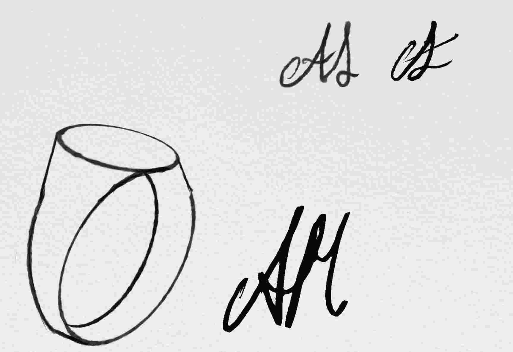
Style exploration
Initial attempts exploring different letterform styles, weights, and spacing on paper.
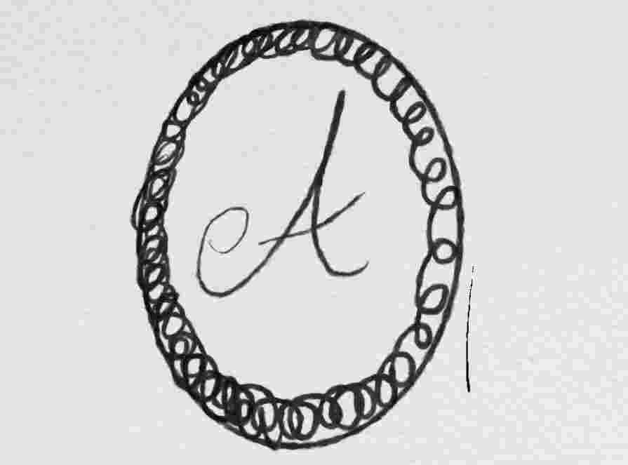
Final hand lettering
The chosen letter, refined and inked — ready to be scanned and vectorized.
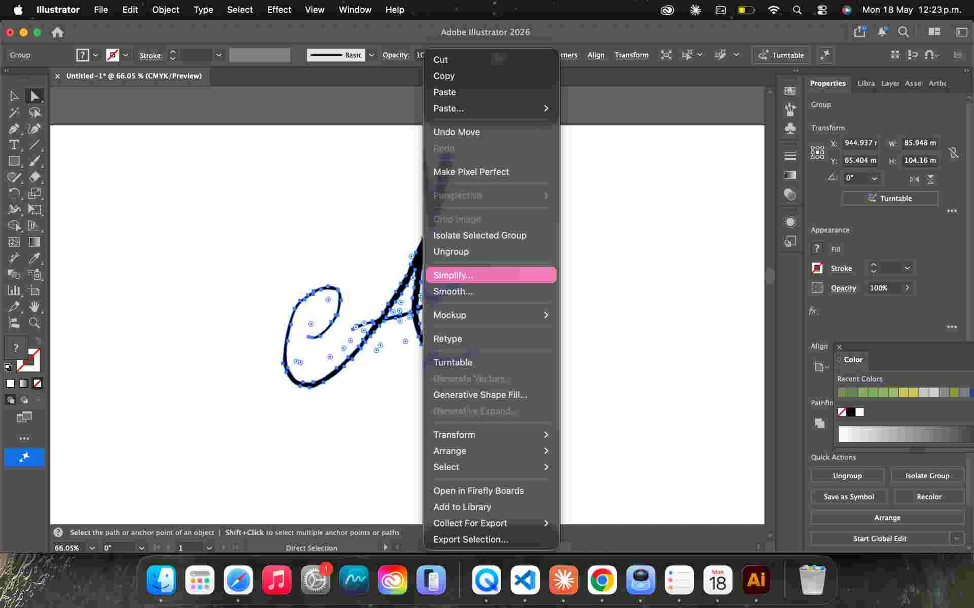
02. Vectorization — Adobe Illustrator
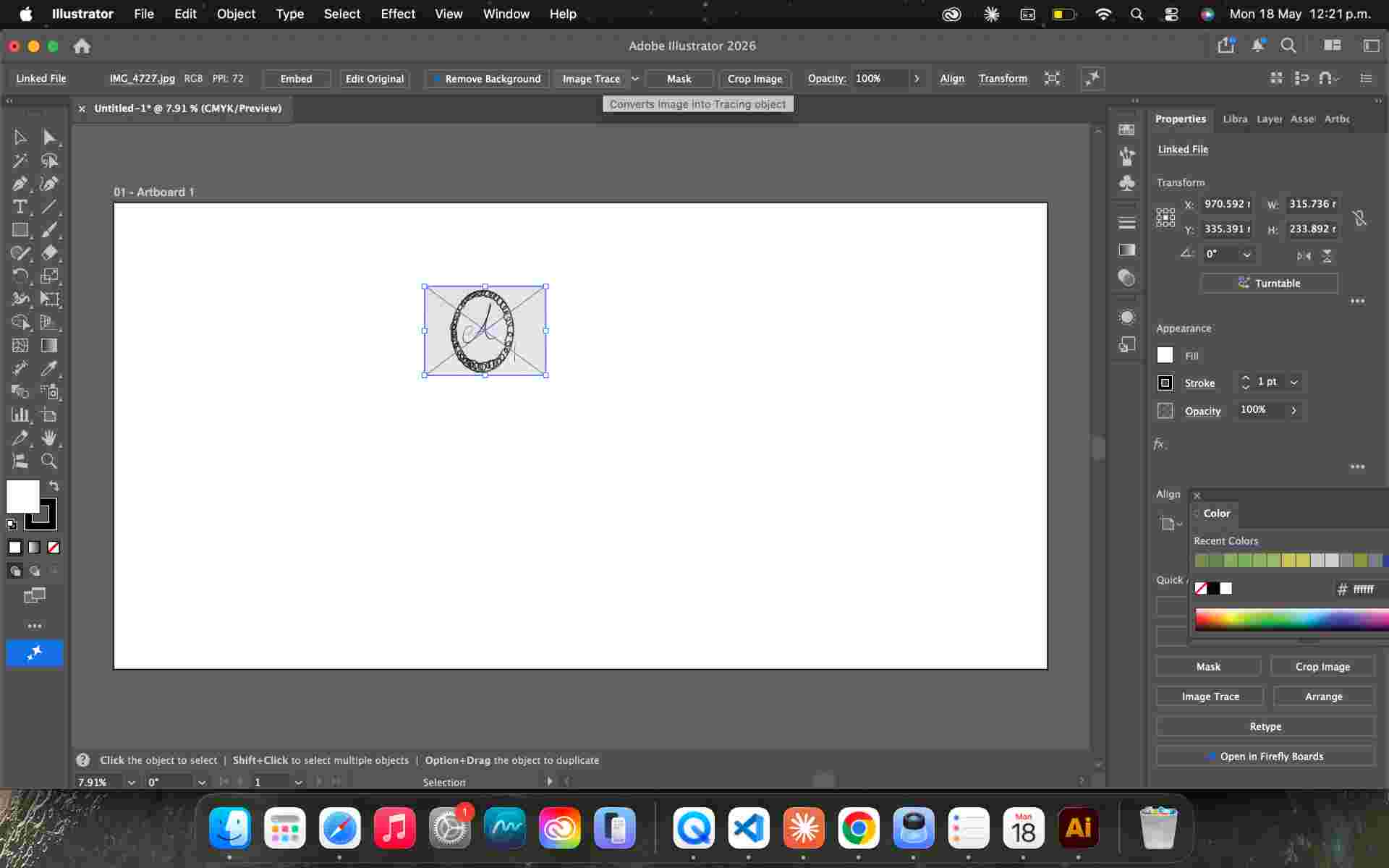
With the hand lettering finalized, I scanned the drawing and opened it in Adobe Illustrator. Using the Image Trace tool, I converted the raster image into a clean SVG vector path. I then refined the result manually — adjusting nodes, smoothing curves, and correcting any distortion from the scan — so the letterform would translate accurately when embedded into the 3D model.
The final SVG is what gets imported into Shapr3D to be extruded as a raised embossment on the surface of the ring band.
Scanned drawing
The inked lettering scanned at high resolution before importing into Adobe Illustrator.
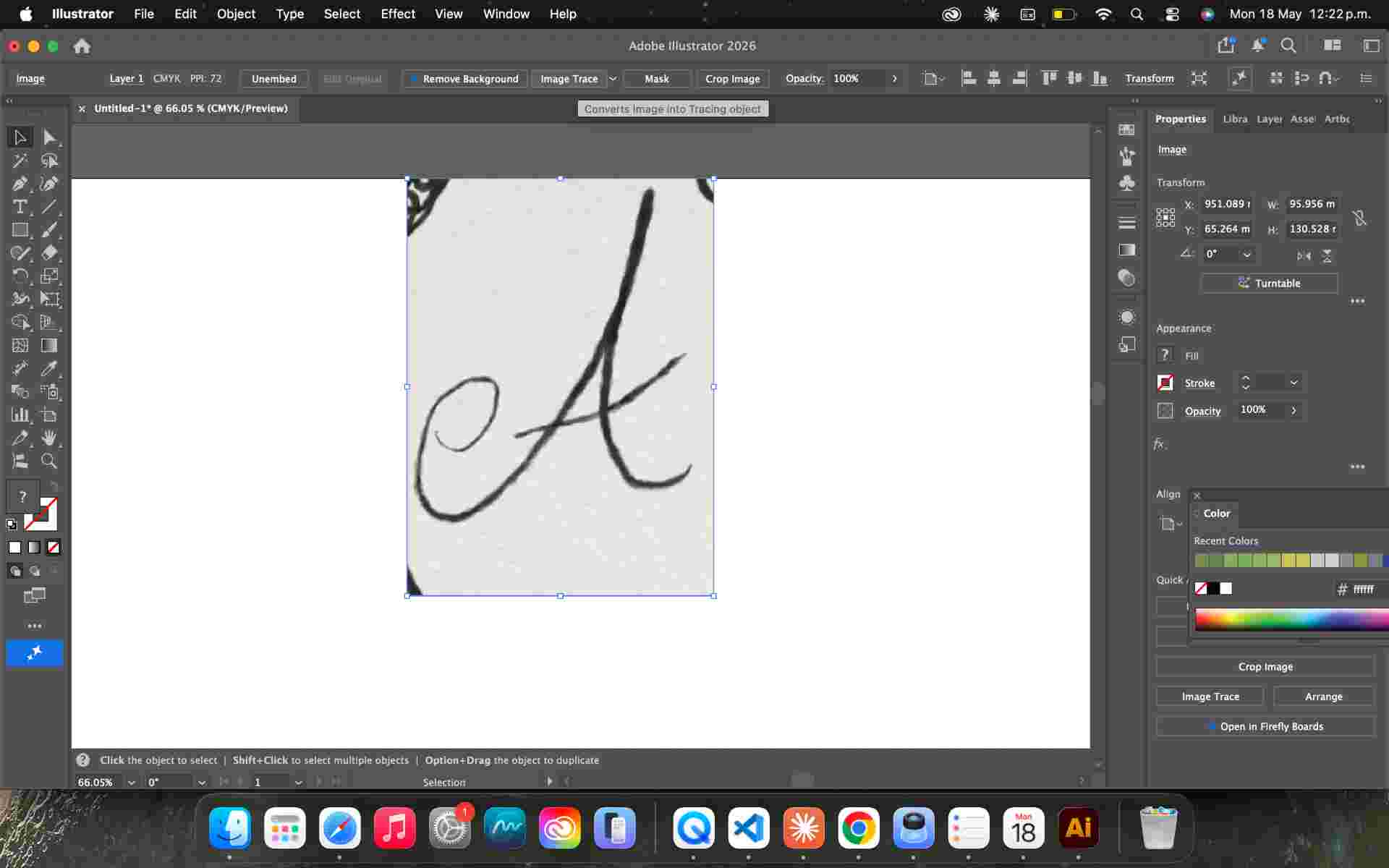
Image Trace
Adobe Illustrator converts the raster image to an SVG path. Initial result before manual node cleanup.
Refined vector
Nodes adjusted and curves smoothed. A clean, watertight path ready for Shapr3D.
03. Ring Design — Shapr3D
With the vector ready, I imported the SVG into Shapr3D. The ring body was built parametrically: a profile sketch based on my ring size, revolved 360° to create the band. The vectorized letter was then extruded from the outer surface of the band as a raised embossment — the defining detail of the piece.
Wall thickness and surface curvature were adjusted to ensure the ring would print cleanly and survive all post-processing steps — sanding, painting, and submerging in the electroplating bath — without cracking or deforming.
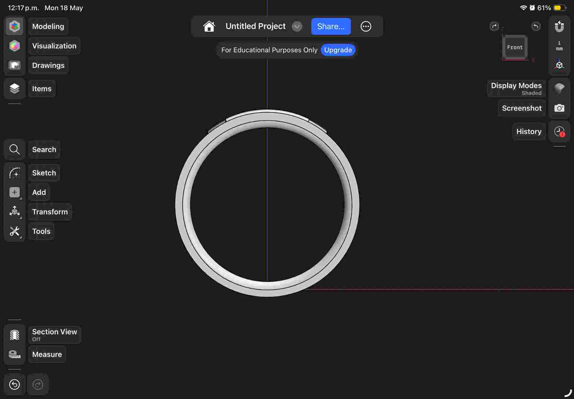
Ring band
Profile sketch revolved 360° to create the band. Sized to my ring measurement.
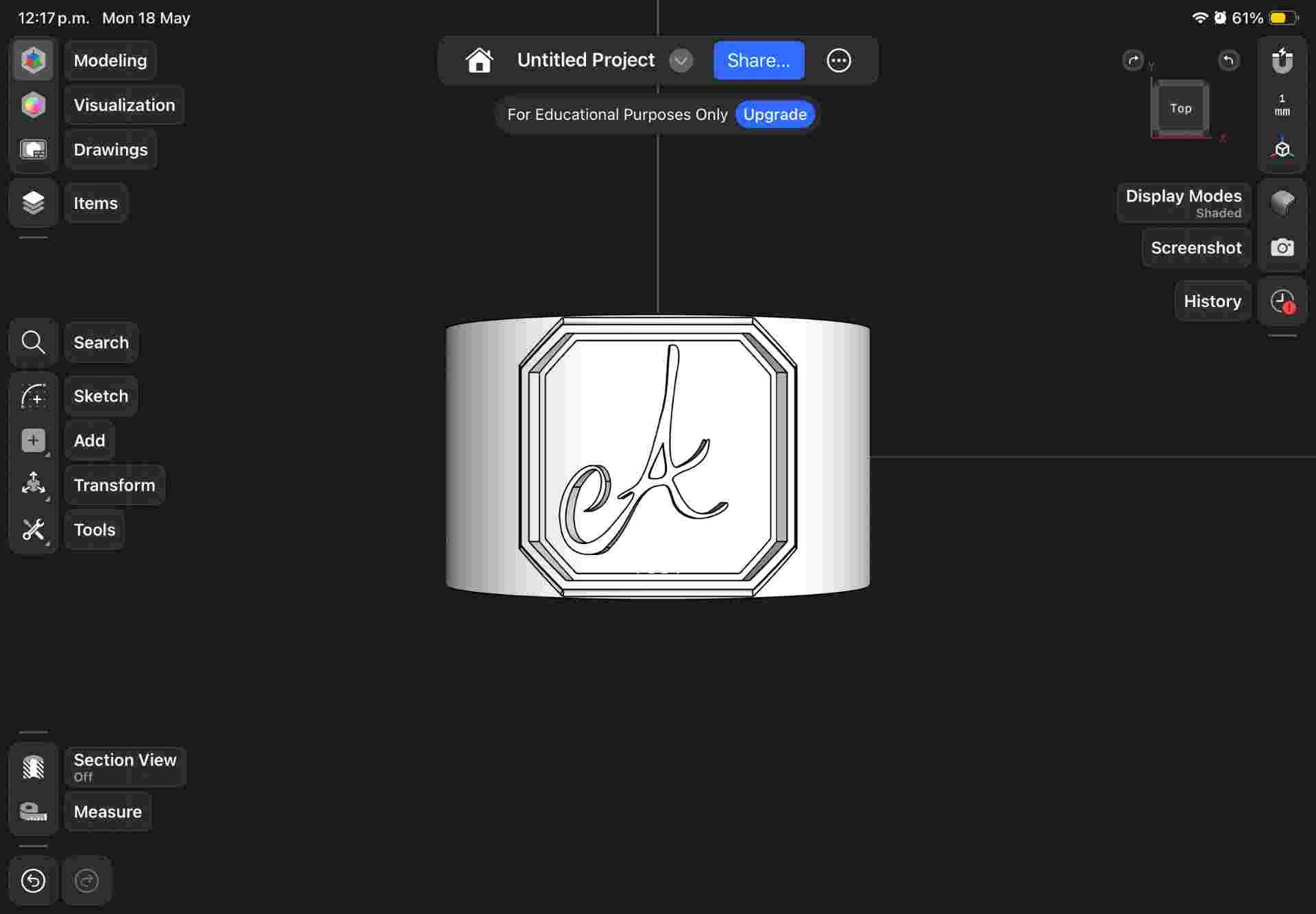
Letter embossment
SVG imported and extruded outward from the band surface. Depth balanced for visibility without fragility.
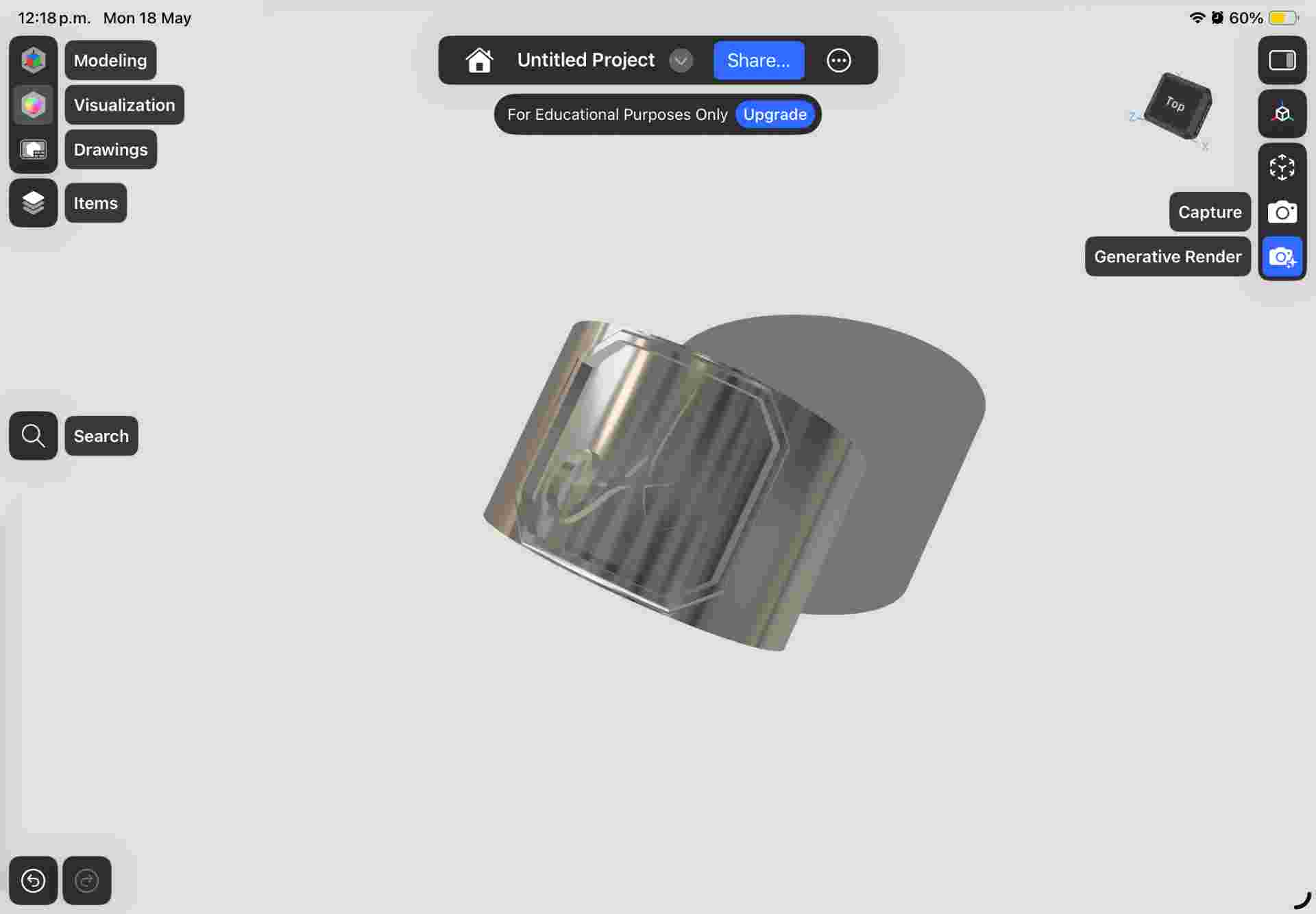
Final model
Completed ring ready for STL export and printing.
| Feature | Decision | Reason |
|---|---|---|
| Band geometry | Revolved sketch | Parametric — easy to adjust for different ring sizes |
| Letter integration | SVG imported, extruded | Preserves the organic quality of the hand-drawn original |
| Embossment depth | 0.6 mm | Visible through the copper plating without making the letter fragile |
| Band thickness | 1.5 mm | Rigid enough to survive sanding and the plating bath |
04. 3D Printing
The ring was printed in PLA using an FDM printer. After printing, the piece was sanded progressively — working through finer grits — to smooth the layer lines on the surface as much as possible before applying the conductive paint.
| Parameter | Value | Notes |
|---|---|---|
| Technology | FDM | Accessible and fast; layer lines addressed with sanding |
| Material | PLA | Easy to print and sand; compatible with conductive paint |
| Layer height | 0.12 mm | Lower layer height to minimize surface texture on the ring band |
| Post-sanding | 400 → 800 grit | Reduces layer lines before conductive paint application |
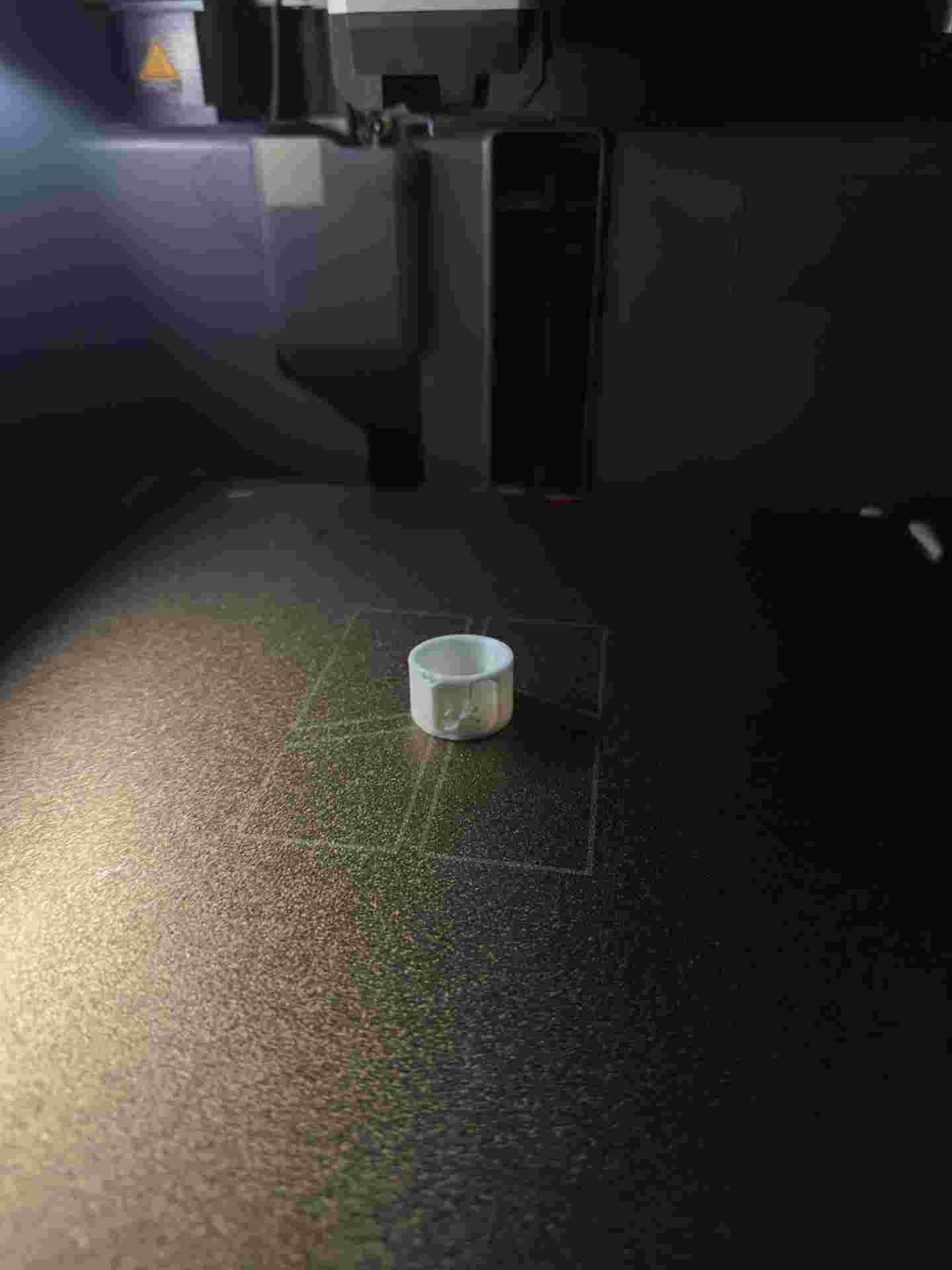
Fresh off the printer
Ring fresh off the FDM printer in PLA. Layer lines visible on the surface before sanding.
05. Electroplating
With the ring sanded and clean, I applied several thin coats of copper-based conductive paint to the entire surface — this primer layer is what allows copper ions to bond during plating. Each coat was left to dry fully before the next was applied.
Once the conductive paint was ready, I set up the electroplating bath: copper sulfate solution in a glass container, copper plate as the anode, ring as the cathode, both connected to a DC power supply at a low, controlled voltage.
| Material / Component | Role | Notes |
|---|---|---|
| 3D printed resin ring | Cathode (−) | Object receiving the copper deposit |
| Conductive copper paint | Primer layer | Makes the non-conductive resin surface plateable |
| Copper plate | Anode (+) | Source of copper ions; dissolves slowly into the solution |
| Copper sulfate solution | Electrolyte | Medium for ion transfer between anode and cathode |
| DC power supply | Current source | Low voltage; drives the electrochemical reaction |
| Glass container | Plating bath | Holds the electrolyte; chemically non-reactive |
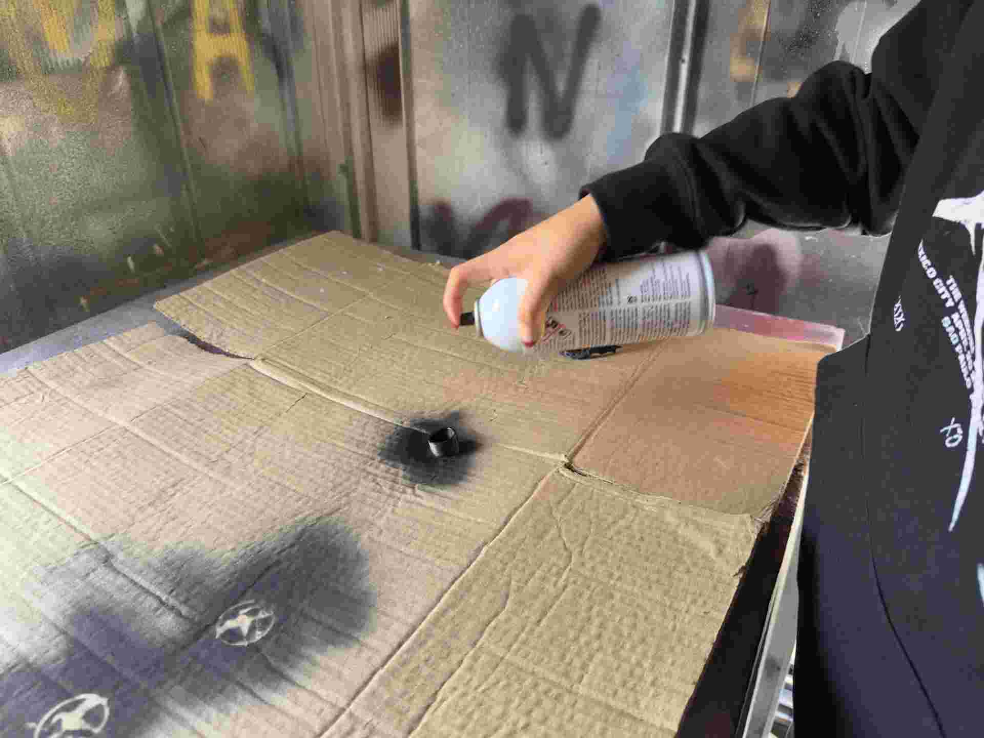
01. Conductive paint
Multiple thin coats of copper-based conductive paint applied evenly over the entire ring surface.
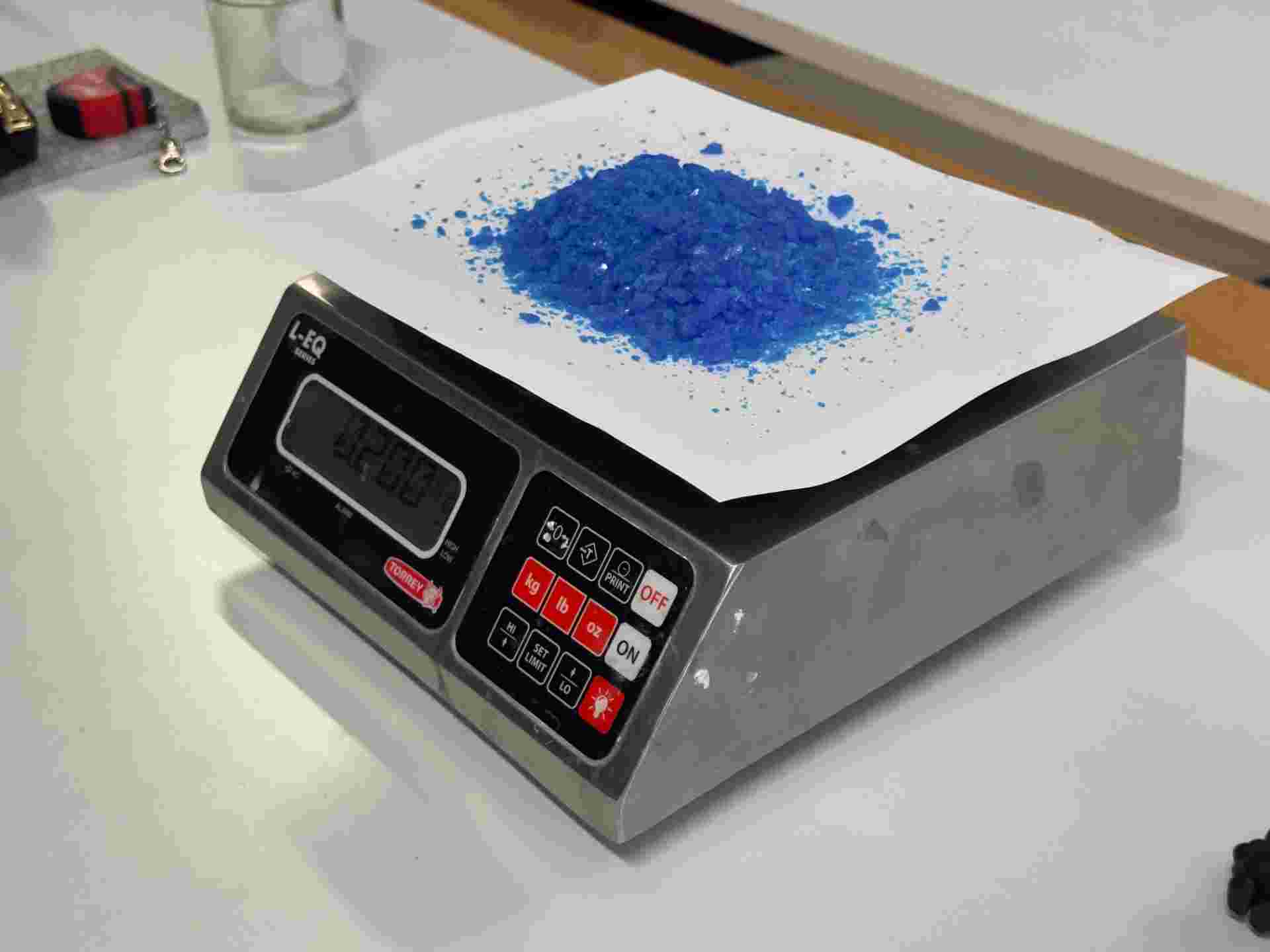
02.Weighting
We need to weight the copper sulfate, the ratio for the bath prep is 200 gr in 1lt of water.
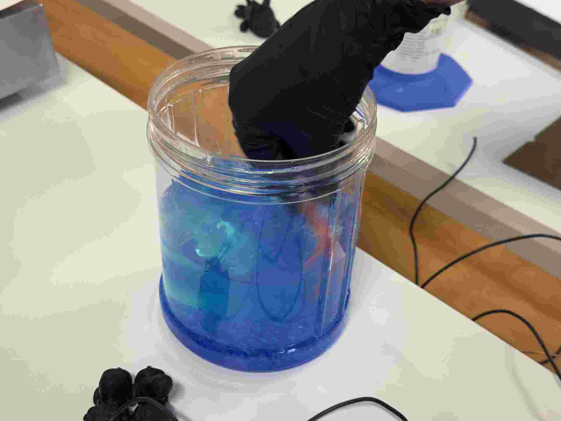
03. Mixing
Mising the copper sulfate in water. It needs to be completly deluted.
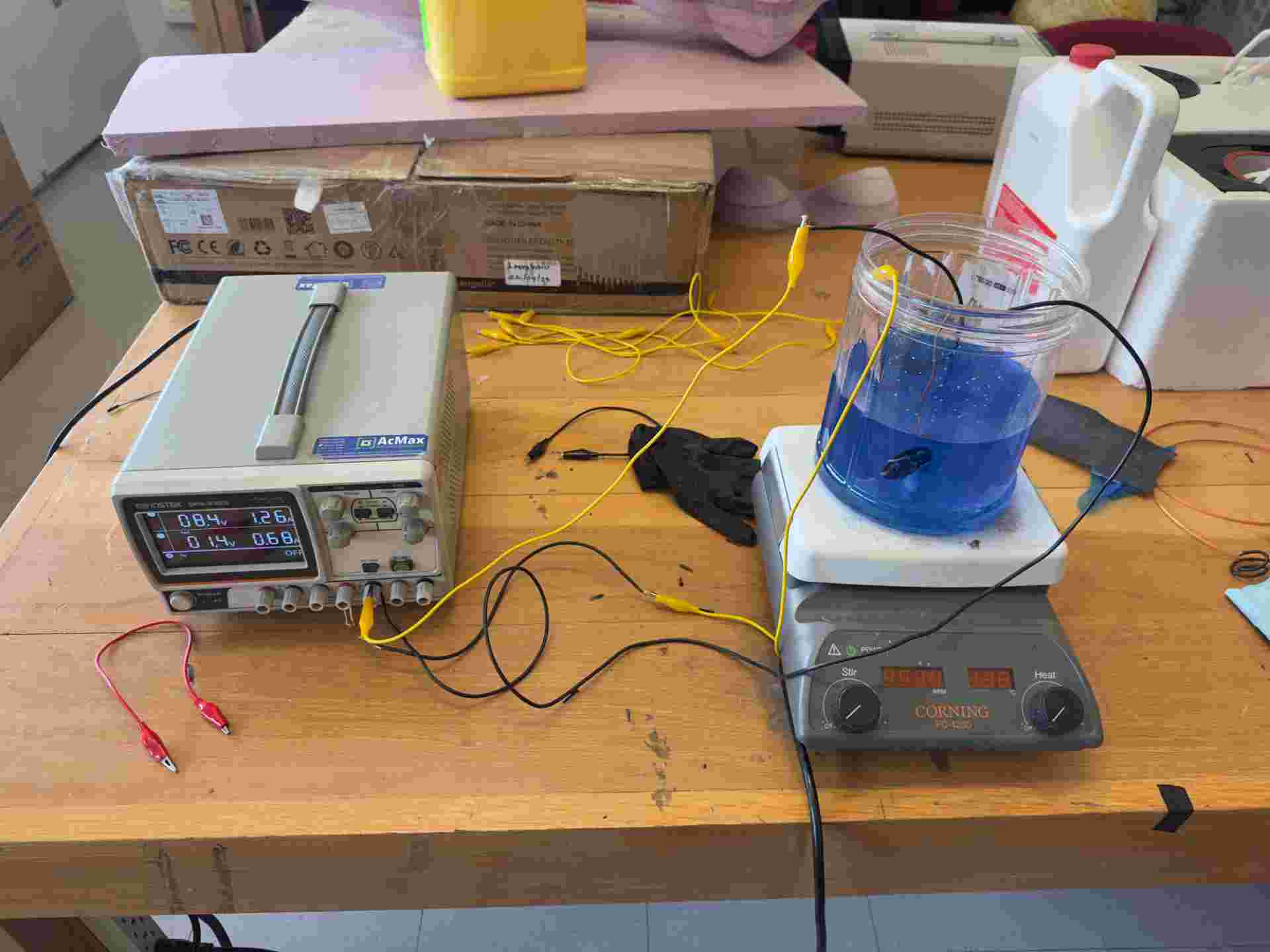
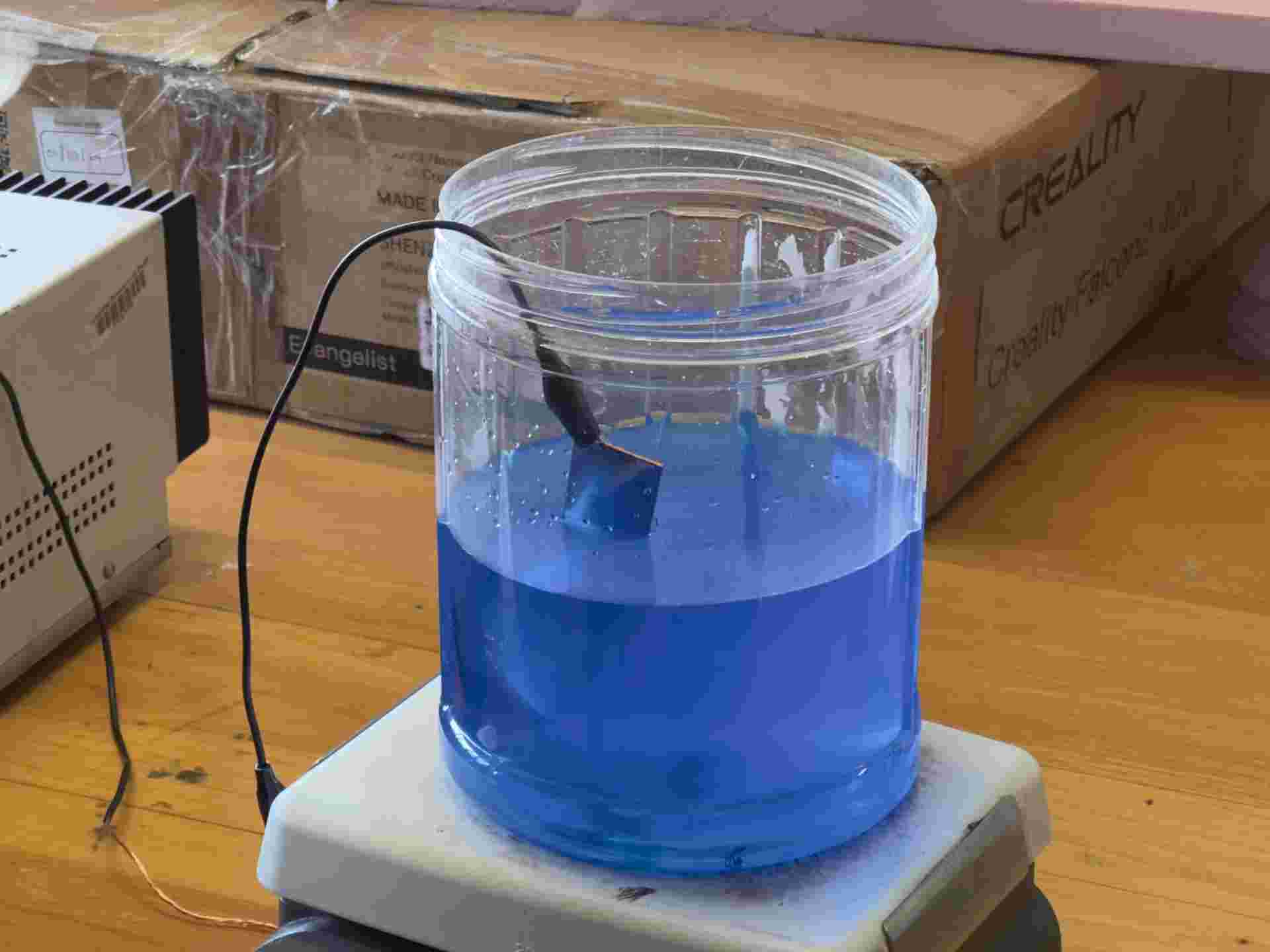
04. Bath setup
Copper anode and ring cathode submerged in the copper sulfate solution. Circuit connected to the DC power supply.
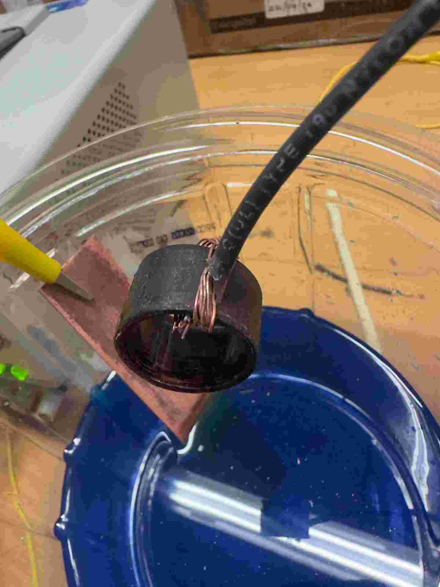
05. Plating in progress
Current on. Fine bubbles on the ring surface confirm the reaction is active and copper is depositing.
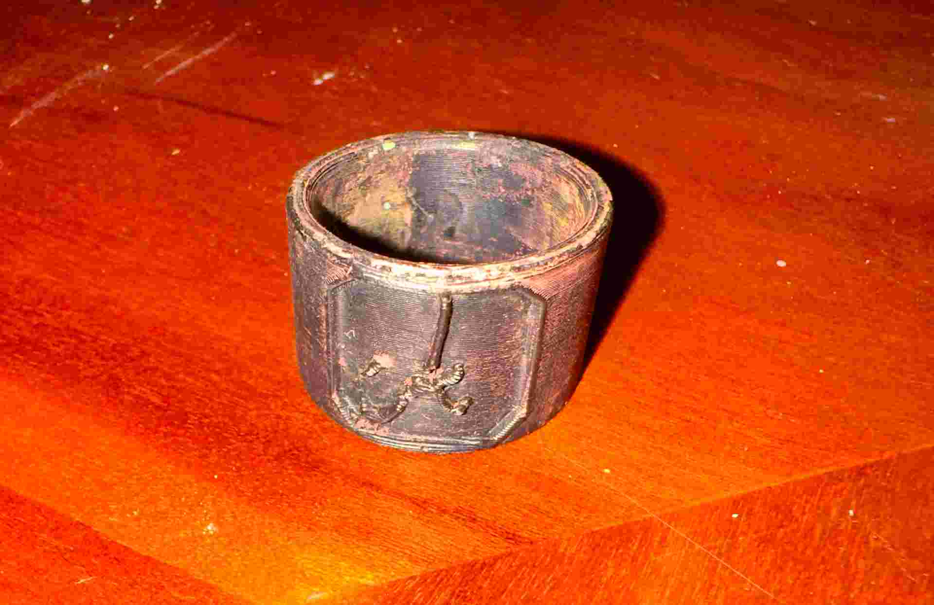
06. Removed from bath
Ring removed after sufficient plating time, rinsed with clean water, and left to dry.
Why the conductive paint is critical
PLA is an insulator, so copper ions have nothing to bond to without a conductive surface. The conductive paint bridges the gap: it creates a metallic primer that connects to the circuit and gives the copper ions a surface to deposit on. Multiple thin coats build coverage without pooling in the letter detail, which would fill in the embossment and lose the design.
No final result — what went wrong
The electroplating did not produce a usable result. After running the bath and removing the ring, the copper had not adhered properly to the surface — the deposit was patchy, weak, and peeled away easily in several areas.
The root cause was the conductivity of the paint. The product used did not have sufficient conductivity to allow an even flow of current across the entire surface of the ring. Areas with lower conductivity received fewer copper ions, resulting in thin or absent deposition. Without a uniformly conductive base layer, the electrochemical reaction cannot distribute evenly — and the copper simply does not bond. A dedicated electroplating conductive primer, or a silver-based conductive paint with a measured resistance below 1 Ω/sq, would be the starting point for a second attempt.
07. Thermoforming — Styrene
As a second process for Wild Card week, I explored thermoforming with styrene sheet. Thermoforming works by heating a thermoplastic sheet in a vacuum thermoforming machine until it becomes soft and pliable, then using vacuum pressure to pull it tightly over a mould so it captures the mould's shape as it cools and stiffens. Styrene is a widely used thermoforming material: lightweight, easy to heat evenly, and able to reproduce mould geometry with good surface detail.
This session was experimental — focused on understanding how styrene responds to heat, how quickly it needs to be worked before stiffening again, and what surface quality the machine can capture from a mould. The specific final object is still being defined.
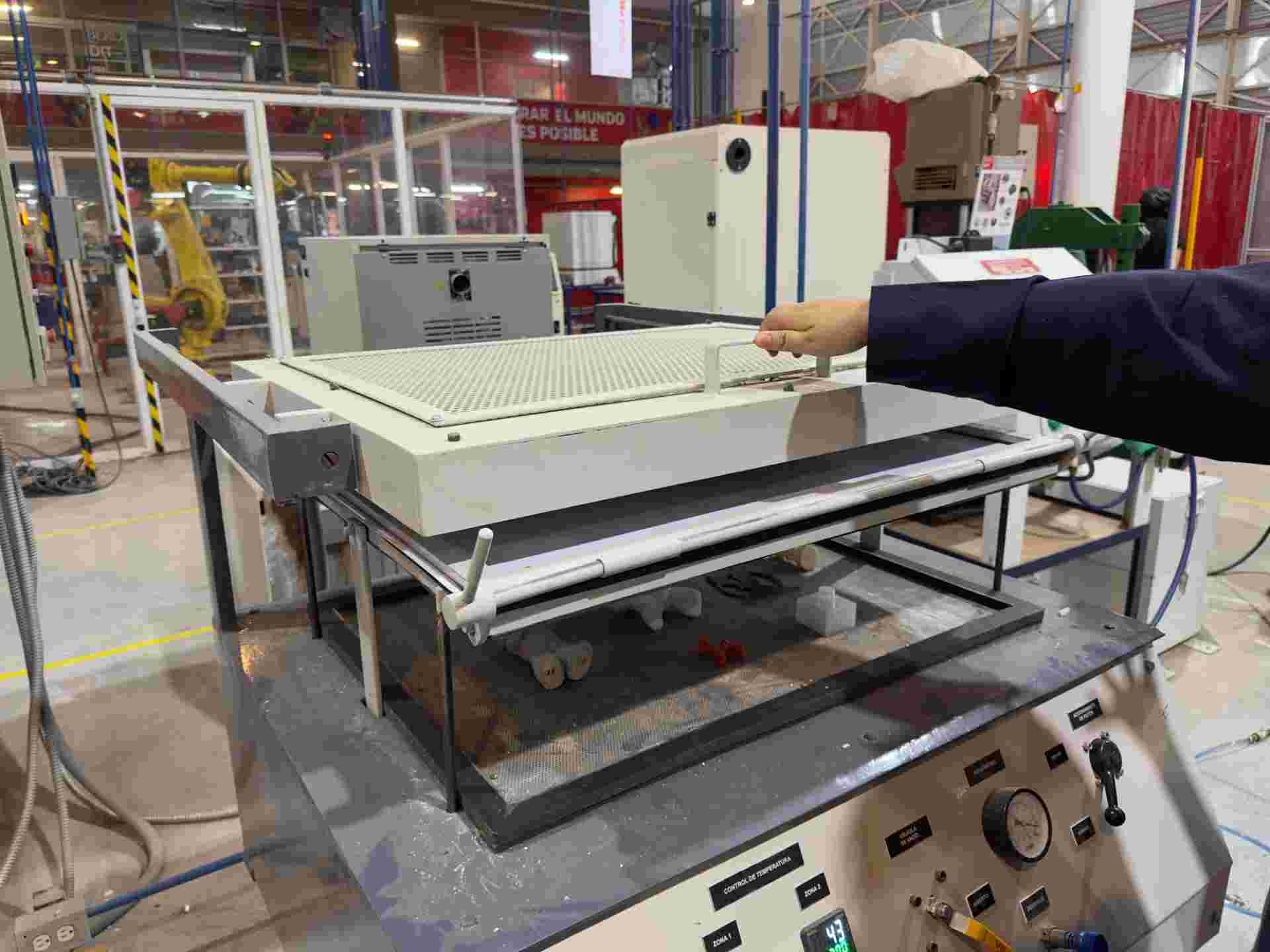
The Thermoforming Machine
A vacuum thermoforming machine works by clamping a thermoplastic sheet above a mould, heating it from above until it softens and sags slightly, then pulling it down tightly over the mould using vacuum pressure applied from below. As the material cools it hardens in the exact shape of the mould capturing surface geometry and fine detail.
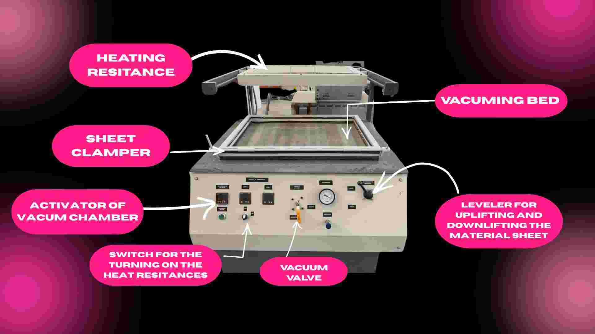
The machine has three main components: the heating element above the sheet, the clamping frame that holds the sheet flat and taut, and the vacuum bed below where the mould sits. When the sheet reaches the right temperature, the operator lowers the frame onto the mould and activates the vacuum, the sheet wraps around the mould in seconds.
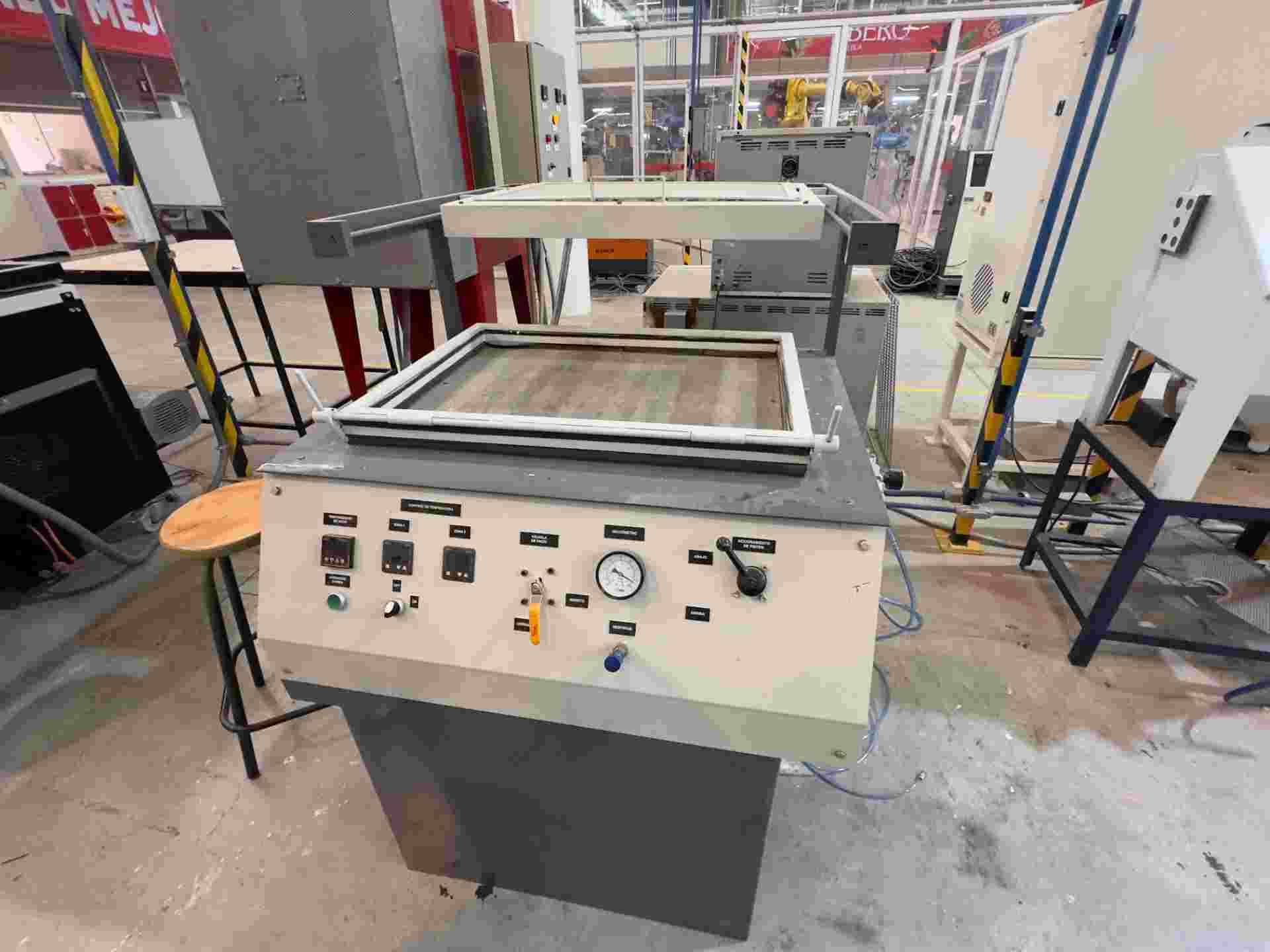
01. The machine
Full view of the vacuum thermoforming machine. Heating element above, vacuum bed and mould platform below.
02. Piece placing
Mould placed and centered on the vacuum bed. No undercuts — ensures clean release once the styrene cools.
03. Sheet clamped
Styrene sheet cut to size and clamped into the machine frame, flat and under even tension.
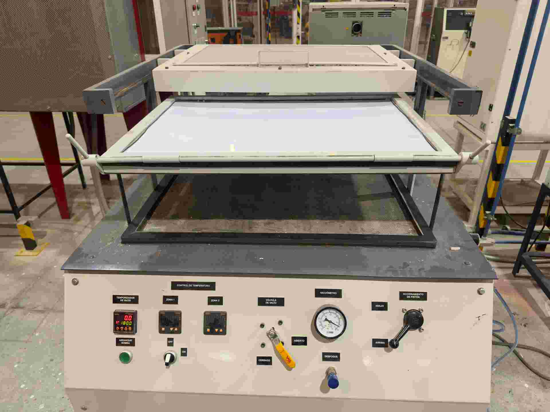
04. Heating
Heating element activated. The styrene softens and sags slightly — the signal that it is ready to form.
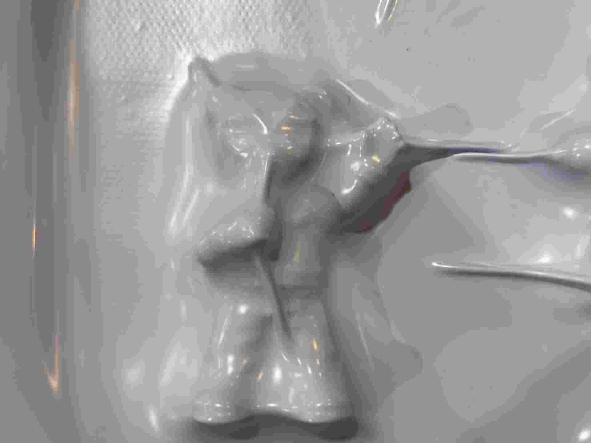
05. Vacuum applied
Frame lowered onto the mould and vacuum activated. The softened sheet pulls tightly down over the mould in seconds.
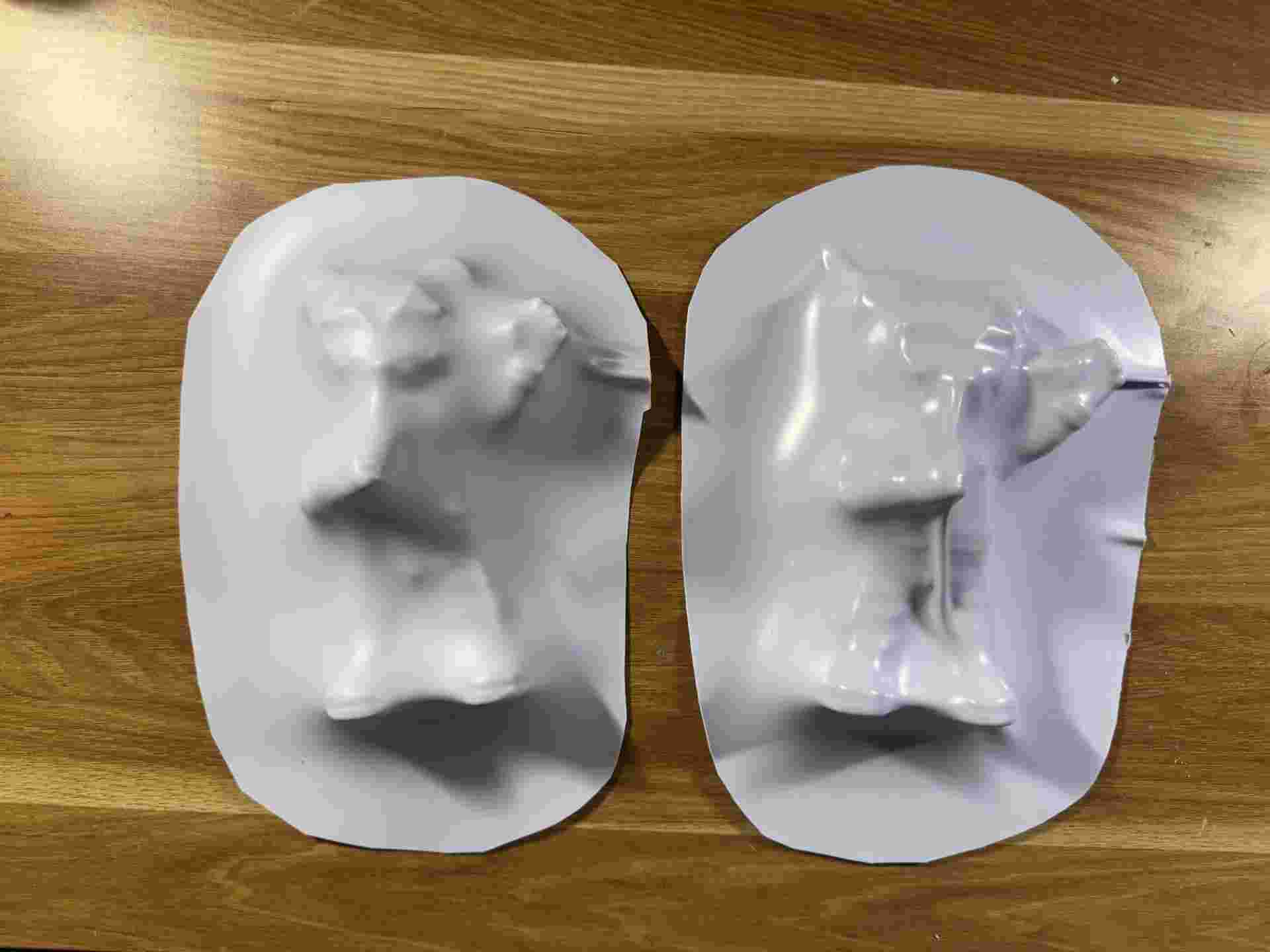
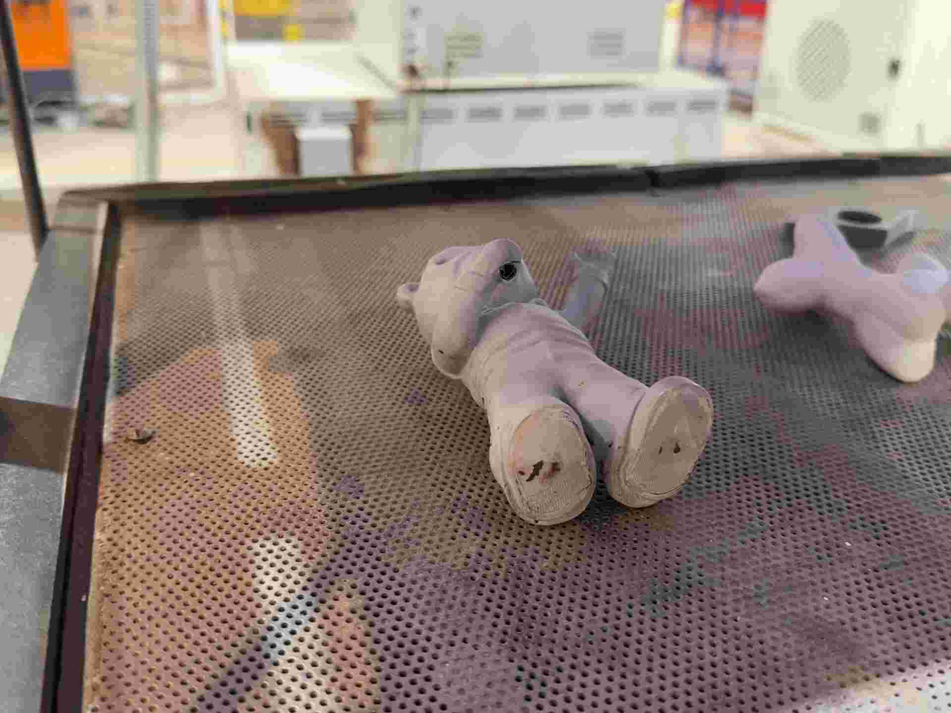
06. Final piece
Cooled styrene released from the mould. Surface detail and conformity to the mould geometry evaluated.
| Parameter | Value | Notes |
|---|---|---|
| Material | Styrene sheet | Lightweight thermoplastic; conforms well to mould geometry |
| Forming method | Vacuum thermoforming machine | Machine heats the sheet and applies vacuum to pull it over the mould |
| Heat source | Machine heating element | Controlled, even heat across the full sheet surface |
| Final object | TBD — experimental session | Process exploration; specific application still being defined |
What I learned about styrene thermoforming
Styrene has a narrow working window — it goes from rigid to pliable quickly with heat, but stiffens again fast once the heat is removed. The forming step has to happen immediately and decisively. Even heating is critical: hot spots cause bubbling or uneven thickness, while under-heated areas resist forming and spring back. The thermoforming machine provides controlled heat and vacuum — the key variable is dialing in the exact temperature and timing for styrene specifically, which varies by sheet thickness.
08. Files
Source files for this week's work.
↓ STL — Ring
You can find the files for the bear in week13