Week 13
Moulding & Casting
.png)
ASSIGNMENT
Design a 3D mould, machine or print it, and cast material in it. Document the full workflow from concept to final cast.
TOOLS
Nomad Sculpt · Shapr3D · 3D Printer · Silicone · Urethane Resin
Personal and Group Assignment
This week's personal assignment was Design a mold around the process you’ll be using, produce it with a smooth surface finish that does not show the production process toolpath, and use it to cast parts.
Group Assignment
Here's the link to our group assignment of this week.
The Process: Moulding & Casting
What is moulding and casting?
Moulding and casting is a manufacturing process that allows you to reproduce a shape multiple times from a single mould. A flexible mould — usually silicone — captures the negative of a positive form. That negative mould is then filled repeatedly with a casting material, producing identical copies each time.
Unlike subtractive or additive fabrication, moulding and casting excels at reproducing complex organic geometry, fine surface detail, and undercuts — in materials that would be difficult to print or machine directly. Once the mould exists, producing copies requires only materials and time.
For this week, I designed the piece from scratch: moodboard, sketches, organic sculpting in Nomad Sculpt, engineering the premould in Shapr3D, printing the premould as the positive form, pouring silicone around it to obtain the negative mould, and finally casting urethane resin in that silicone mould.
Positive premould → negative silicone mould
The premould is the positive: a printed shell whose outer surface carries the exact geometry of the final piece. It sits inside a containment box and liquid silicone is poured around it,filling the space between the premould and the box walls. When the silicone cures and is separated from the premould, its inner surface is the negative: a perfect impression of the piece, ready to receive resin.
Designing the premould in Shapr3D — built around the organic sculpt from Nomad Sculpt means all geometry decisions are made digitally. The printed positive is the single physical step between the CAD file and the silicone mould.
My Process
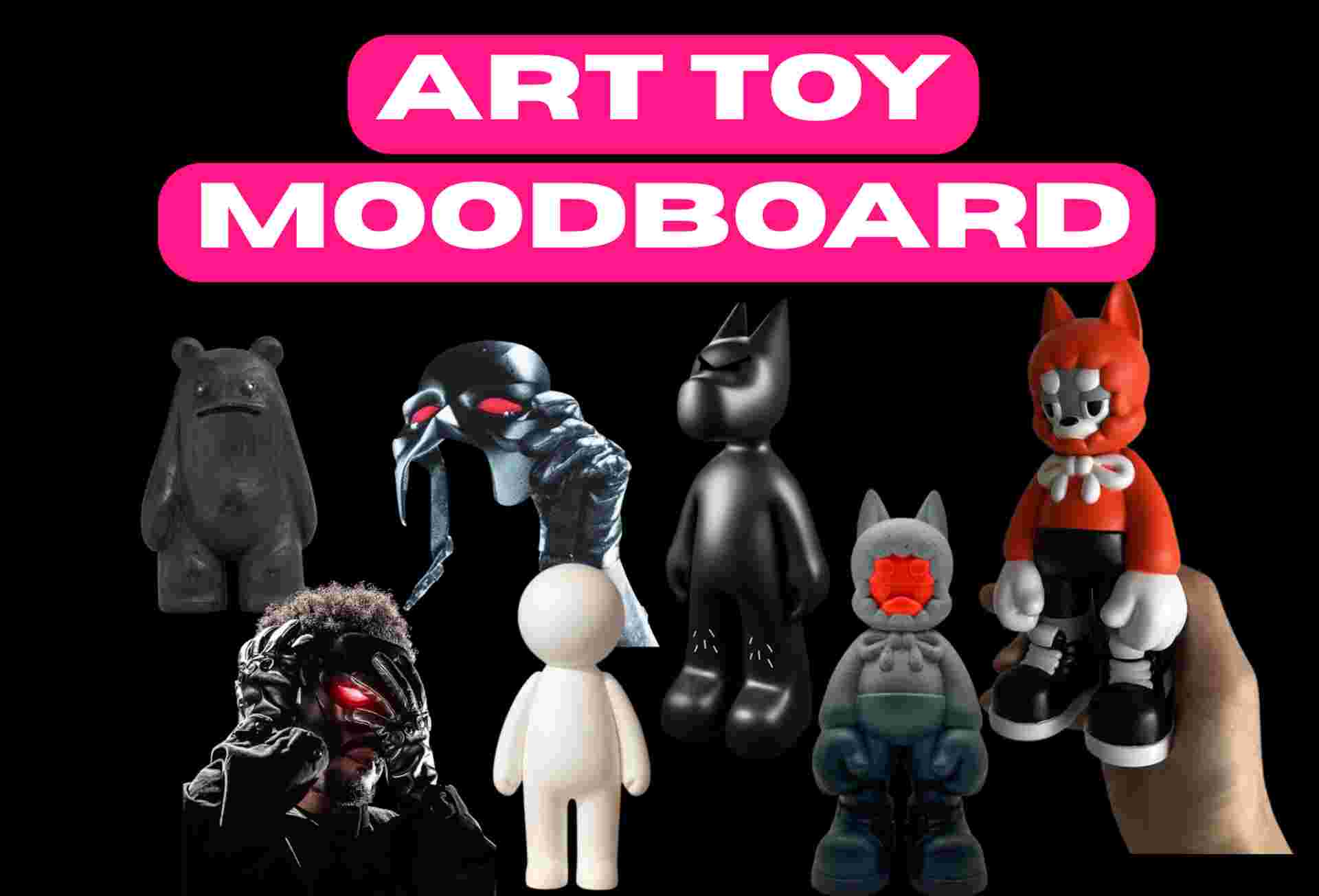
00. Moodboard & Inspiration
The design process started with research and visual references. I built a moodboard gathering forms, textures, and objects that inspired the direction of my piece focusing on organic shapes and surface detail that would translate faithfully through a silicone mould.
The references helped me define the aesthetic direction before opening any software: soft, flowing contours that would highlight the silicone's ability to capture fine geometry.
01. Sketches
Before opening any software, I sketched ideas on paper to explore proportions, silhouette, and where the parting line of the two-part mould would fall. Because the premould is the positive that defines the silicone cavity, the parting line has to be decided before the Shapr3D model is built — it becomes the plane that splits the premould into two halves, each surrounded by its own silicone pour.
I settled on a symmetrical split along the centerline: no undercuts on either half, and a clean translation into the Boolean cut in Shapr3D.

Form exploration
Initial sketches exploring silhouette and proportions before committing to a final direction.
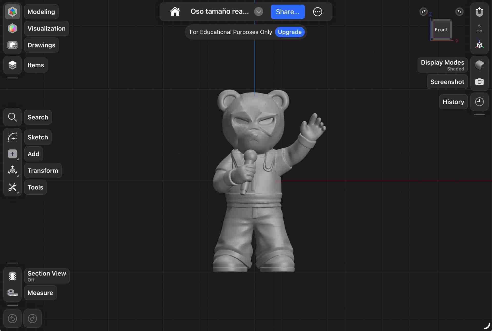
02. Digital Sculpting — Nomad Sculpt
With the sketches as reference, I modelled the piece in Nomad Sculpt. The design required flowing, non-geometric surfaces that are far more natural to sculpt than to model parametrically. I built the form from a base primitive using the standard, move, crease, and inflate brushes to develop the surface and refine the silhouette.
This sculpt is the positive form of the final piece. It was exported as OBJ and brought into Shapr3D, where it became the reference geometry around which the premould body — with its containment walls, registration features, and parting plane — was constructed.
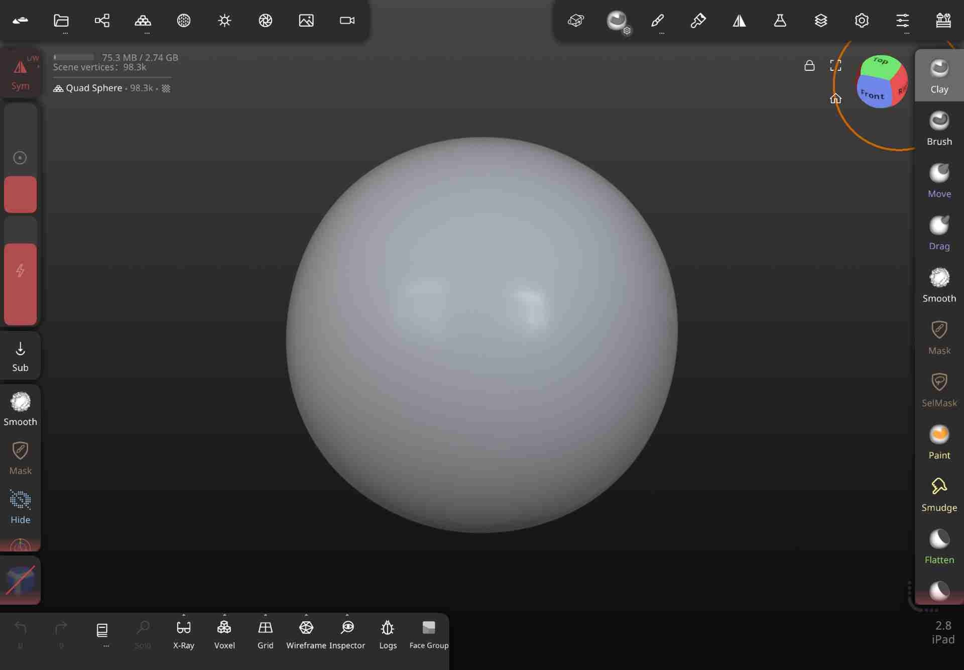
Base form
Starting from a primitive, overall silhouette roughed in with the standard and move brushes.
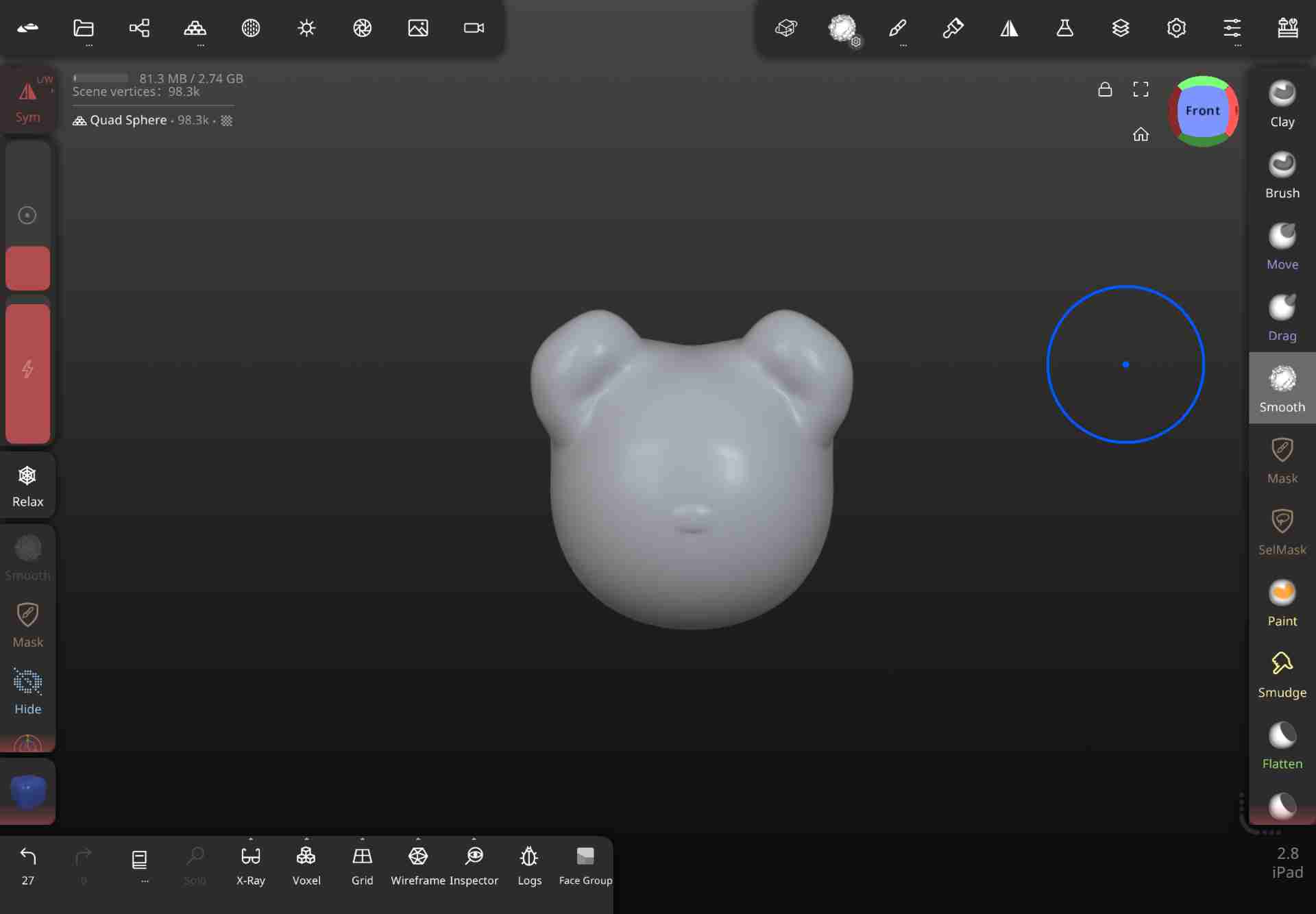
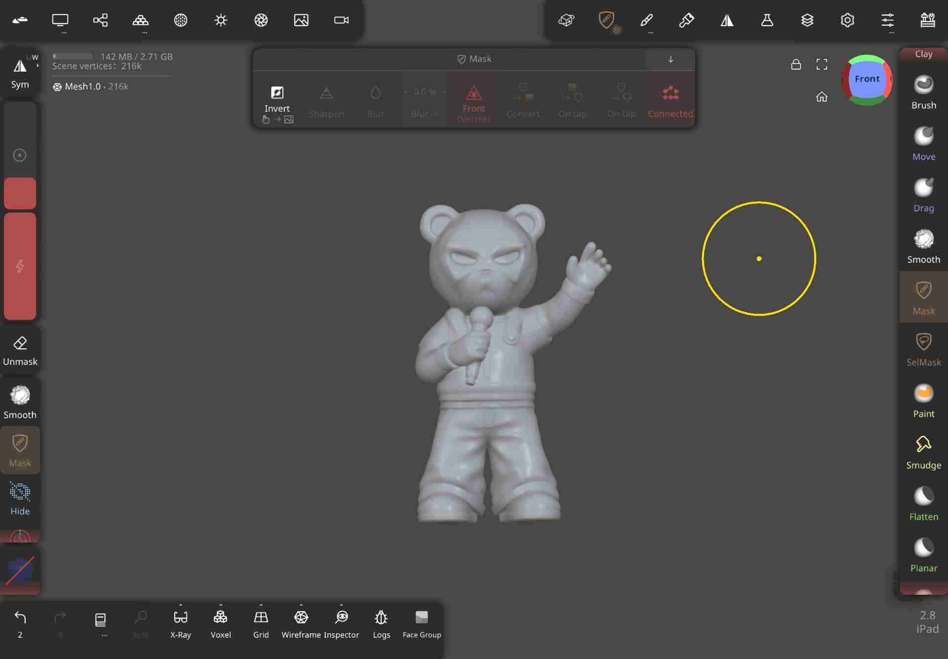
Surface detail
Crease and inflate brushes used to develop the surface character and refine transitions.
Final sculpt → OBJ export
Completed model exported as OBJ — the positive form that Shapr3D uses as the core of the premould design.
Why Nomad Sculpt for the positive?
Organic forms — the kind that read as hand-made and tactile — are far easier to develop through brush-based sculpting than through parametric CAD. Nomad Sculpt handles the aesthetics; Shapr3D handles the engineering. The OBJ export is the bridge between the two: the sculpted form imported as a mesh body that Shapr3D can reference to build the premould geometry around it.
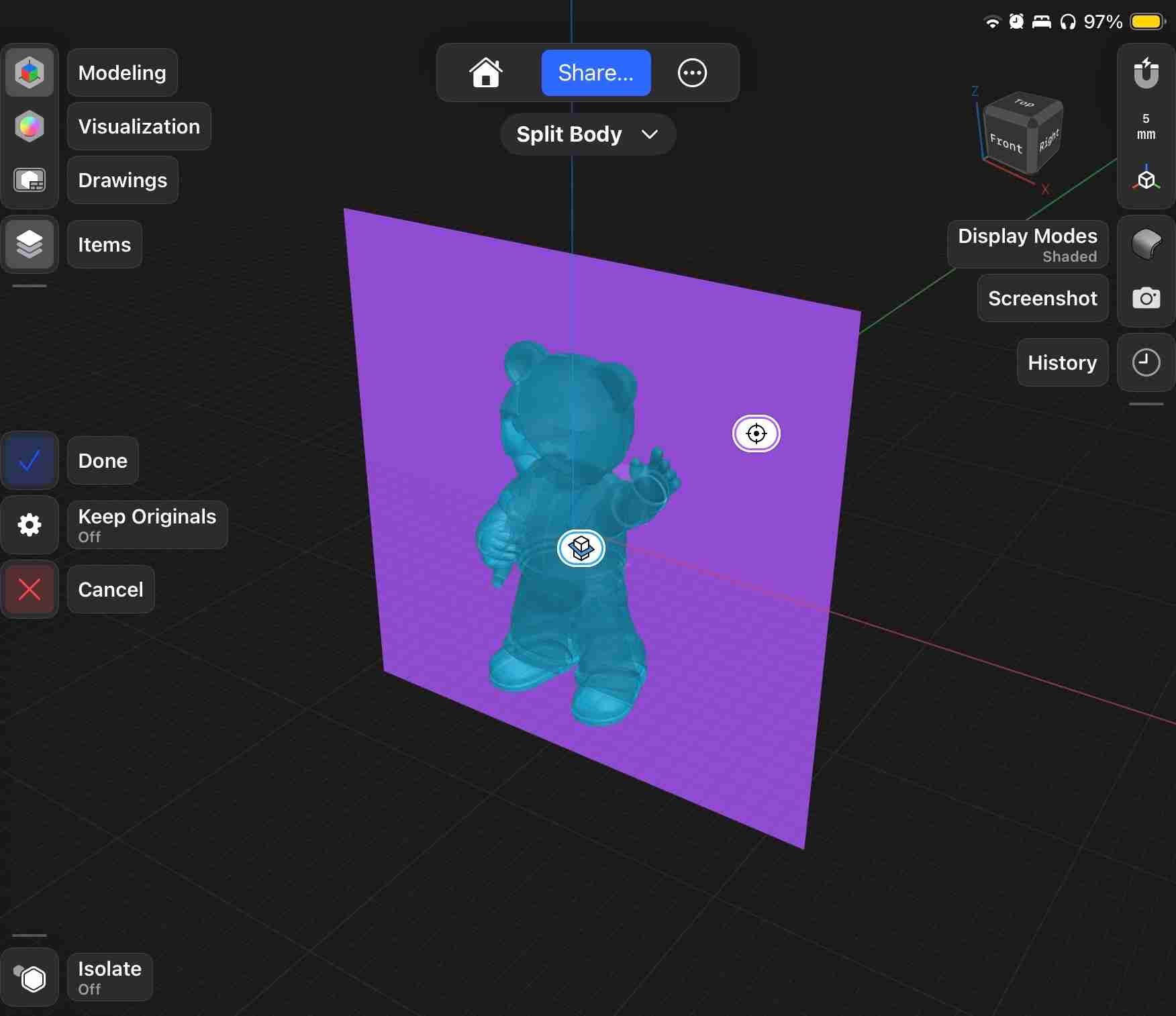
03. Premould Design — Shapr3D
The OBJ from Nomad Sculpt was imported into Shapr3D as the core positive body. Around it, I built the premould: a printed shell that wraps the positive and integrates all the geometry needed for the two-part silicone pour. A planar Boolean cut split the assembly into two halves along the parting line defined in the sketches.
Each half of the premould has the sculpted form on its inner face — this is the surface the silicone will contact. The outer walls of each half form the containment box for the silicone pour. Registration pins between the halves ensure the two silicone pieces align precisely when assembled for casting.
Positive body imported
The Nomad Sculpt OBJ brought in as the positive core. Premould walls constructed around it.
Parting cut & features
Planar cut splits the assembly into two halves. Registration pins, sprue channel, and vent added.
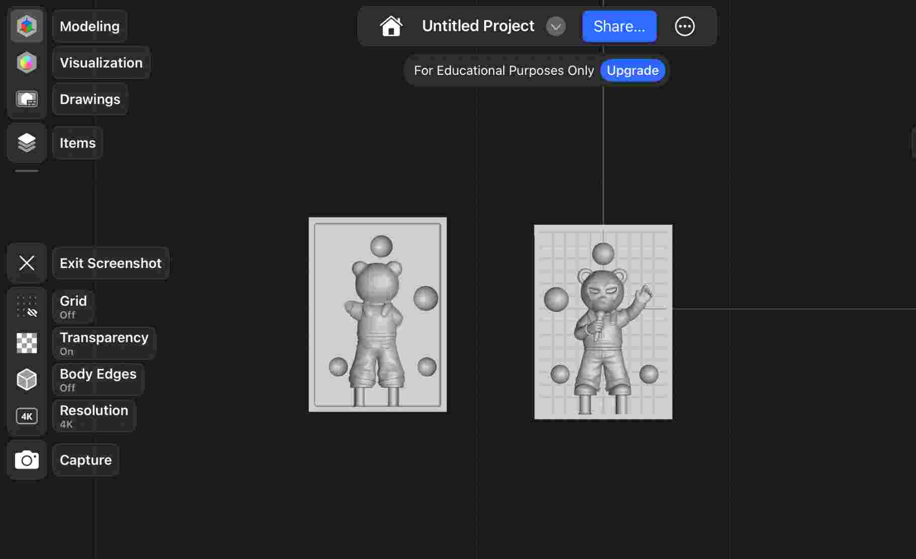
Final premould halves
Two halves exported as separate STLs. Each carries the positive form on its interior face.
| Feature | Decision | Reason |
|---|---|---|
| Positive geometry | Nomad Sculpt OBJ imported | Organic form defined in sculpting app; premould built around it |
| Parting plane | Symmetrical centerline | No undercuts on either half; clean silicone separation |
| Containment walls | [X mm] thick | Rigid enough to hold liquid silicone without flexing |
| Registration pins | Interlocking, both halves | Silicone halves align precisely when assembled for resin casting |
| Sprue | Top center of mould | Gravity-assisted fill; minimal air entrapment |
| Vent | Highest point of cavity | Trapped air escapes during resin pour |
The premould as positive + containment box in one
In a traditional workflow, the positive (master) and the containment box are two separate things: the master is positioned inside a box, clay fills the parting line gap, and the box walls define only the outer boundary of the silicone block. Here, the premould integrates both roles — the sculpted form sits on the interior face, and the surrounding walls form the box — all in a single printable part. This means the parting geometry is precisely controlled in CAD rather than improvised with clay.
04. Printing the Premould
Both premould halves were 3D printed. The exterior surface of each half carries the positive geometry — this is the surface the silicone contacts, so its quality matters. Layer lines on this face will transfer to the silicone mould and then to every resin cast. The outer walls prioritise rigidity over surface finish.
| Parameter | Value | Notes |
|---|---|---|
| Printer | [Bambu Lab P1S] | FDM |
| Material | [PLA] | — |
| Layer height | [0.16 mm] | Lower = smoother positive surface → better silicone detail |
| Infill | [15%] | Denser = stiffer walls; resists silicone pressure |
| Supports | [Yes] | Removed and sanded before use |
| Print time | [14 hours] | Total time if all parts printed separetly |
- 1 Printed both premould halves; removed any supports carefully.
- 2 Sanded the positive-geometry face to reduce layer line texture.
- 3 Test-fitted the two halves using the registration pins — verified alignment at the parting line.
- 4 Applied mould release to the positive surfaces so the cured silicone separates cleanly.
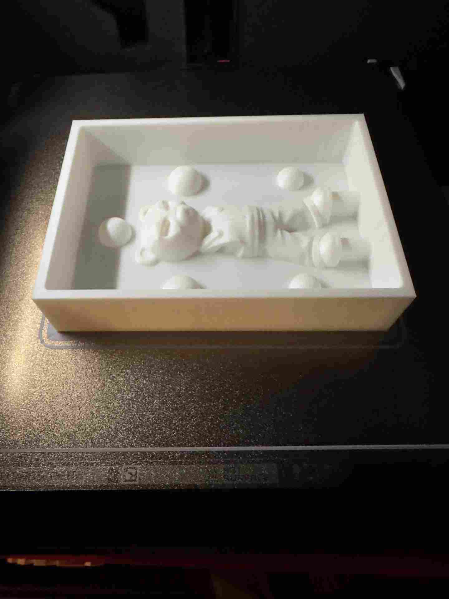
Fresh off the printer
Both premould halves after printing. The sculpted positive geometry is visible on the inner face of each half.
05. Silicone Pour — Capturing the Negative
With the premould printed and treated with mould release, I poured liquid silicone into each half of the premould assembly. The silicone flows around the positive form and into the containment walls, filling the space between the positive geometry and the outer shell. Once cured, the silicone is removed from the premould — and its inner surface is the negative impression of the piece, ready to receive resin.
Because the premould acts as both positive and containment box, each half is poured and cured independently. Mould release on the first silicone half before the second pour prevents the halves from fusing.
| Parameter | Value | Notes |
|---|---|---|
| Silicone | Smooth On | Addition-cure |
| Shore hardness | [XX A] | Softer = easier demould of finished casts |
| Mix ratio | 1:100 by weight | Weighed on digital scale |
| Pot life | 20 min | Working time after mixing |
| Cure time per half | 8 hours | Fully cured before removal from premould |
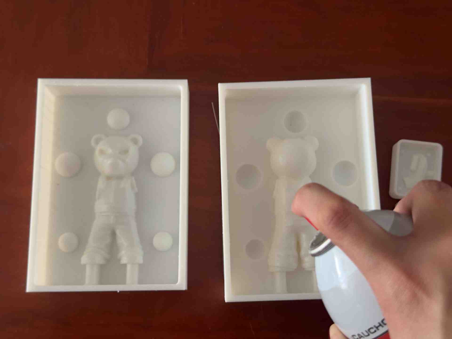
01. Mould release applied
Applied mould release evenly to all positive surfaces of the first premould half.
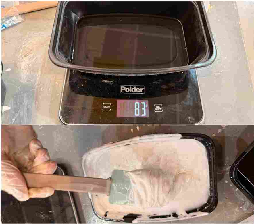
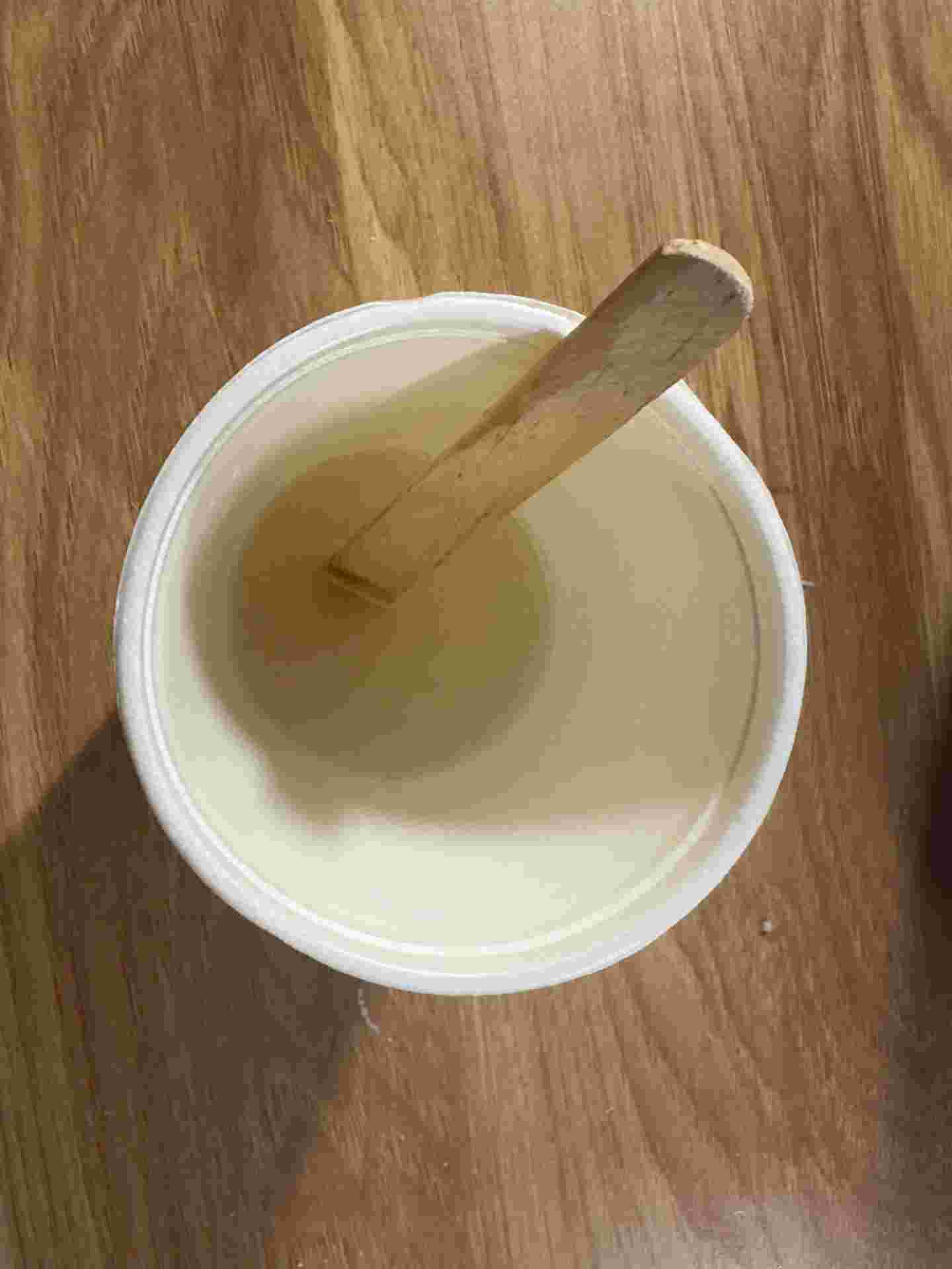
02. Mixing silicone
Mixed silicone by weight; poured slowly from height around the positive form to break surface bubbles.
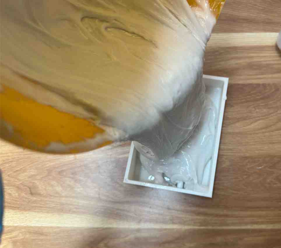
03. Pouring
Pour the silicone to the premould.
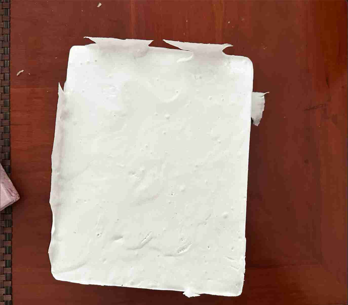
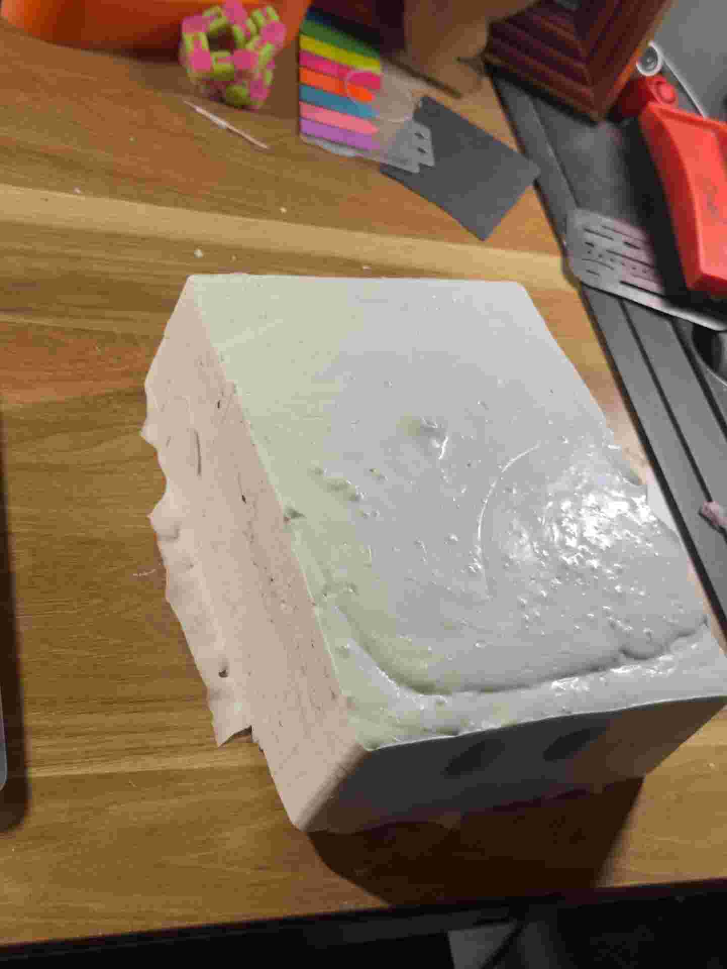
04. Curing
Left to cure fully inside the premould shell. The printed walls hold all geometry without additional support.
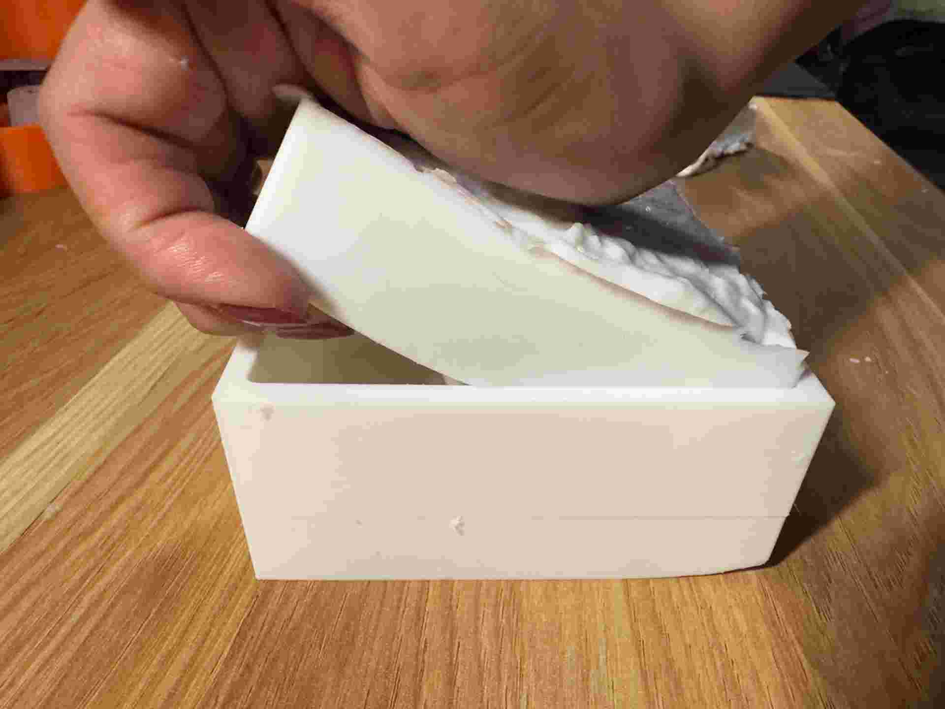
04. Removing from premould
Cured silicone half removed from the premould. Negative surface inspected for bubbles or defects.
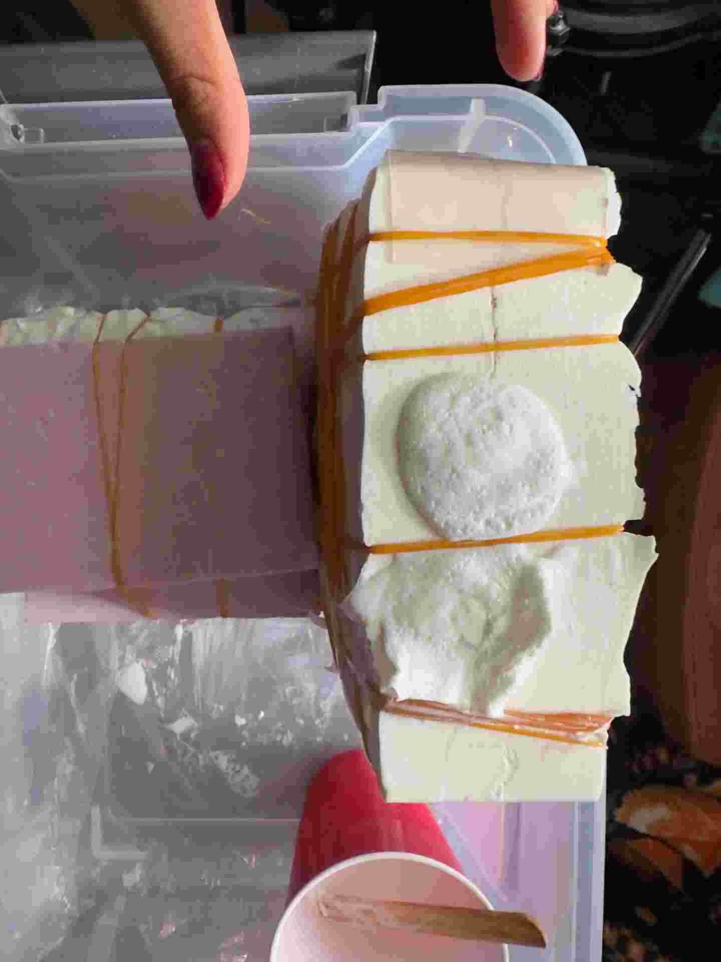
06. Mould assembled
Both silicone halves assembled. The inner surface is the complete negative of the piece, ready for resin casting.
Critical: mould release between silicone halves
Before the second silicone pour, mould release must be applied to the already-cured first half. Silicone bonds permanently to itself — skipping this step would fuse the two halves into a solid block with the premould trapped inside. The same applies to the premould surface: release agent on the positive geometry is what allows the cured silicone to separate cleanly and carry the full impression of the form.
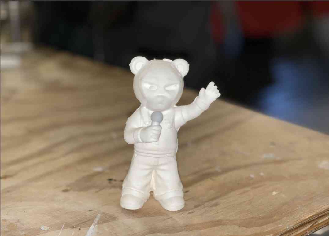
06. Urethane Resin Casting
With the two-part silicone mould assembled, I cast urethane resin into the negative cavity. The resin fills the impression left by the positive premould — and the finished cast is a faithful reproduction of the original sculpted form.
| Parameter | Value | Notes |
|---|---|---|
| Resin | [EPSA] | Urethane casting resin |
| Mix ratio | [1:1 by volume] | Measured precisely |
| Pot life | [5 min] | Pour before this time |
| Demould time | [60 min] | Part still warm when removed |
| Full cure | [24 hours] | Before final handling or finishing |
- 1 Aligned silicone halves using registration features; secured with rubber bands.
- 2 Measured and mixed resin components precisely by volume.
- 3 Poured slowly through the sprue; tilted mould to guide resin into all areas.
- 4 Monitored the vent for overflow — confirming a full fill.
- 5 Waited for demould time, then carefully opened the silicone mould.
- 6 Trimmed the sprue stub and any parting line flash with a craft knife.
Mixing
Components measured and mixed carefully.
Pour
Poured slowly through the sprue. Mould tilted to eliminate air pockets inside the negative cavity.
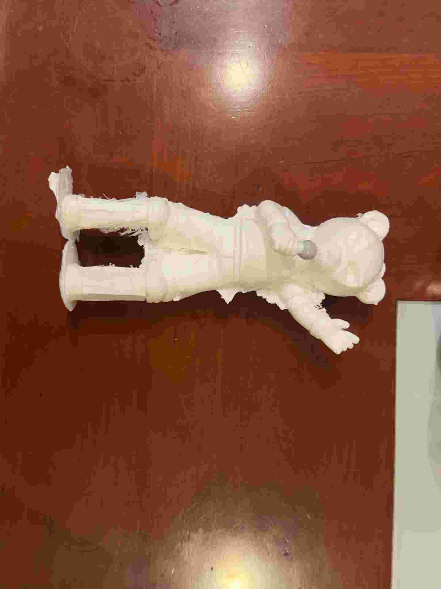
Demould
Cast removed after demould time. Sprue stub and parting line flash trimmed with a craft knife.
07. Materials & Safety
Both silicone and urethane resin require careful handling. I reviewed the SDS sheets for all materials before starting and used appropriate PPE throughout the process.
Silicone
Flexible, tear-resistant mould material. Captures the positive geometry of the premould at high resolution and releases the resin cast cleanly. Reusable across multiple pours.
Urethane resin
Fast-cure, rigid casting material. Reproduces the silicone negative faithfully. Paintable and sandable after cure. Produces an exothermic reaction — watch heat buildup in thick sections.
PPE used
Nitrile gloves, safety glasses, and a ventilated workspace throughout all chemical handling steps. Waste resin fully cured before disposal.