Final Project
Krypto Support

ABOUT
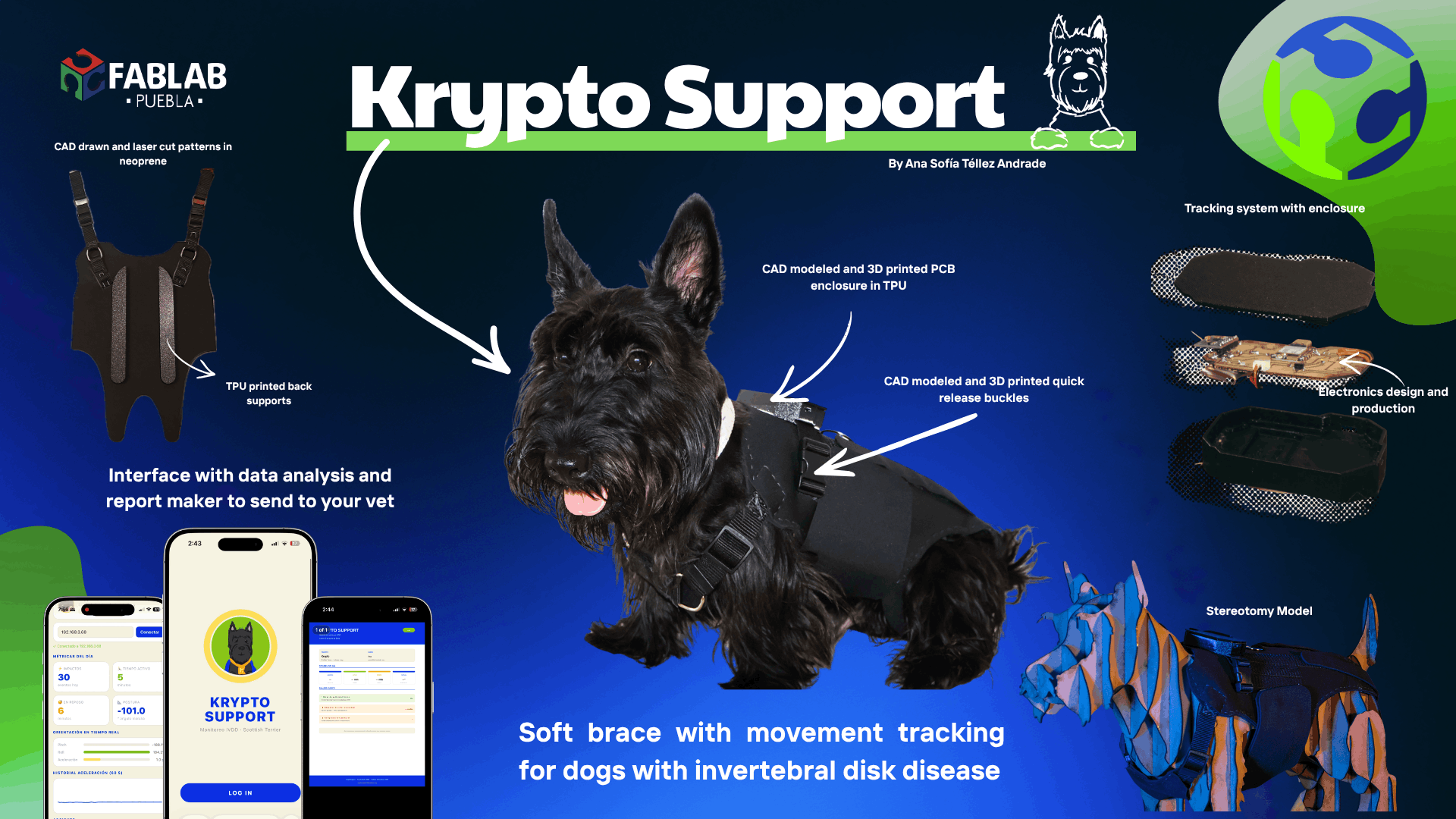
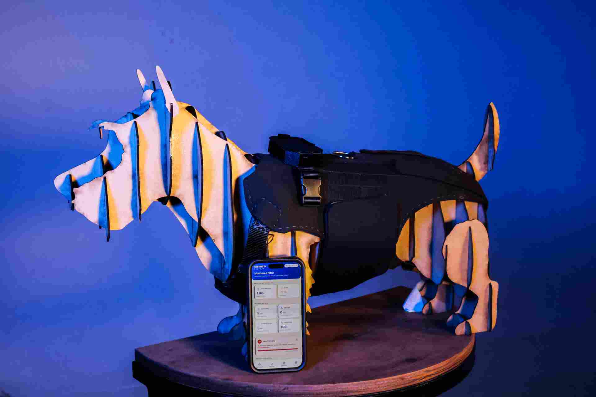
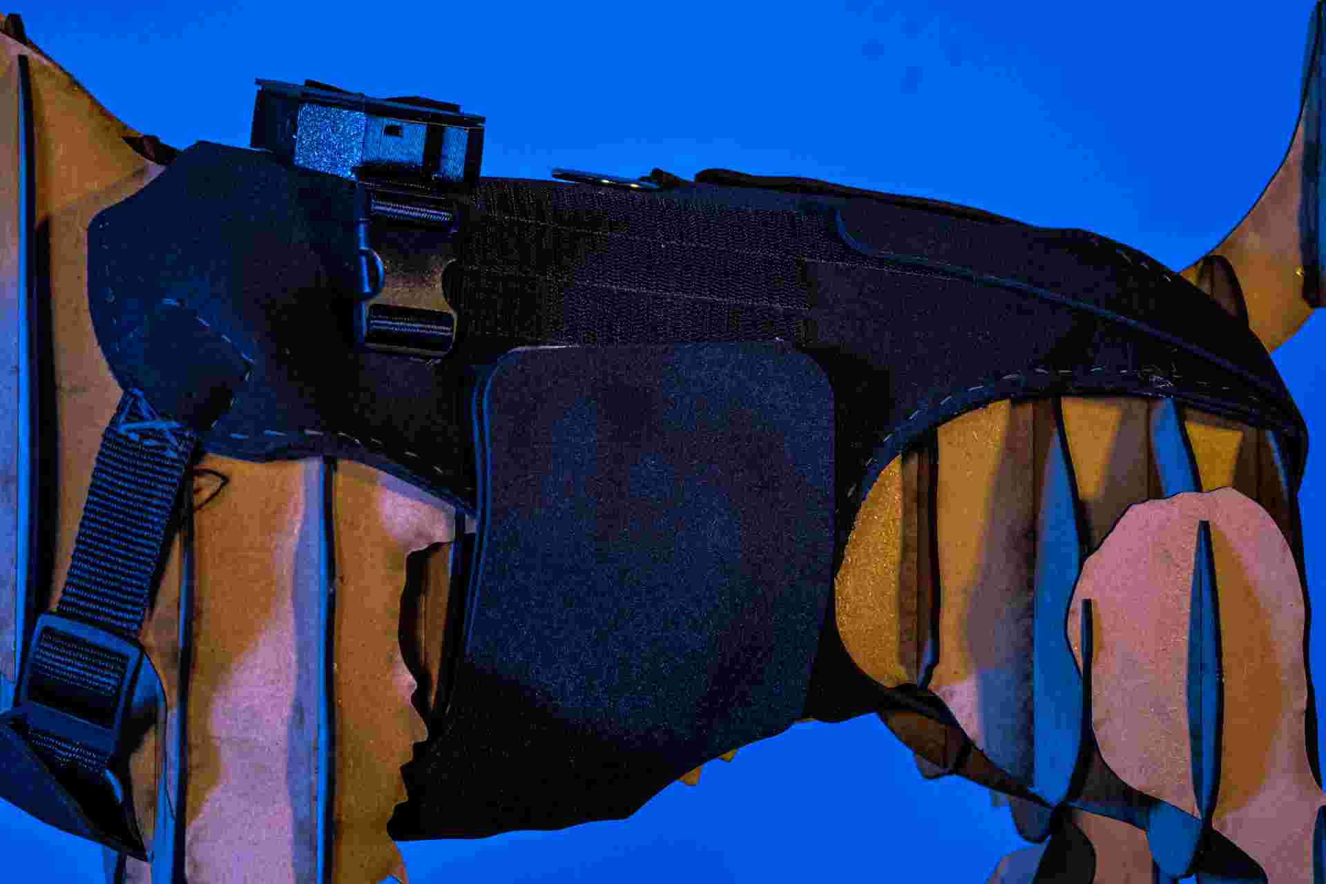
A support brace with impact-absorbing system and IMU motion tracking, designed to help pets with spinal compression conditions.
DISCIPLINES
3D Design · Electronics · Fabrication · Programming
Presentation
Final Slide
Project Video
Deliberation Process
How I arrived at this idea
This is Krypto
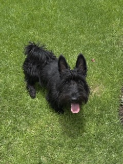
1 year old Scottish Terrier diagnosed with Intervertebral Disc Disease (IVDD)
The deliberation process started from a very personal place — my own dog's diagnosis. Watching Krypto struggle with everyday movements made me ask whether fabrication could offer something that didn't yet exist commercially.
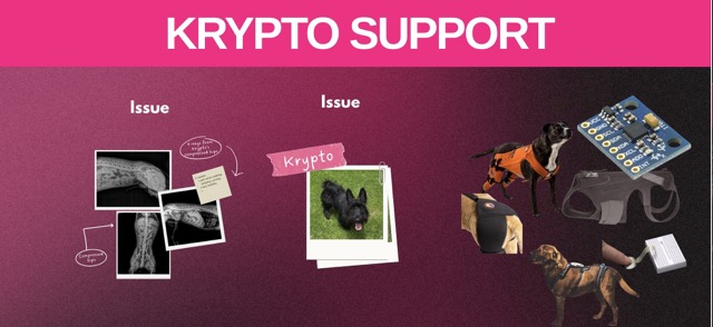
Most commercially available braces for pets are either too generic, too rigid, or don't address the specific biomechanical challenge of spinal impact during movement. That double gap — mechanical and diagnostic — became the starting point for Krypto Support.
Ideas I considered before deciding
Option A — Generic pet monitor
Discarded — already exists commercially and doesn't address the mechanical problem of spinal impact.
Option B — Rigid orthopedic brace
Discarded — rigid braces limit natural movement and can cause secondary issues.
Option C — Krypto Support ✓
Selected — addresses both mechanical and diagnostic needs simultaneously.
Inspiration & References
Looking at similar projects helped me understand what was possible and where existing solutions fell short.
Why this project matters
IVDD affects a large percentage of certain dog breeds. Most owners manage the condition reactively. Krypto Support aims to shift that toward proactive monitoring, giving veterinarians real movement data rather than relying solely on owner descriptions of symptoms.
What is Krypto Support?
Project overview
Krypto Support is a support brace designed with an impact-absorbing system that helps reduce the stress generated during different movements such as walking, running, and jumping. This system reduces the overall impact received by pets with spinal compression conditions in the hip area.
Additionally, the design incorporates an IMU system to track the pet's daily movements and detect anomalies, allowing this information to be shared with a veterinarian to support better diagnosis and treatment. IMU sensor integration is documented in Week 9 → Input Devices.
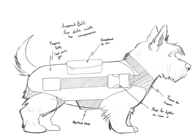
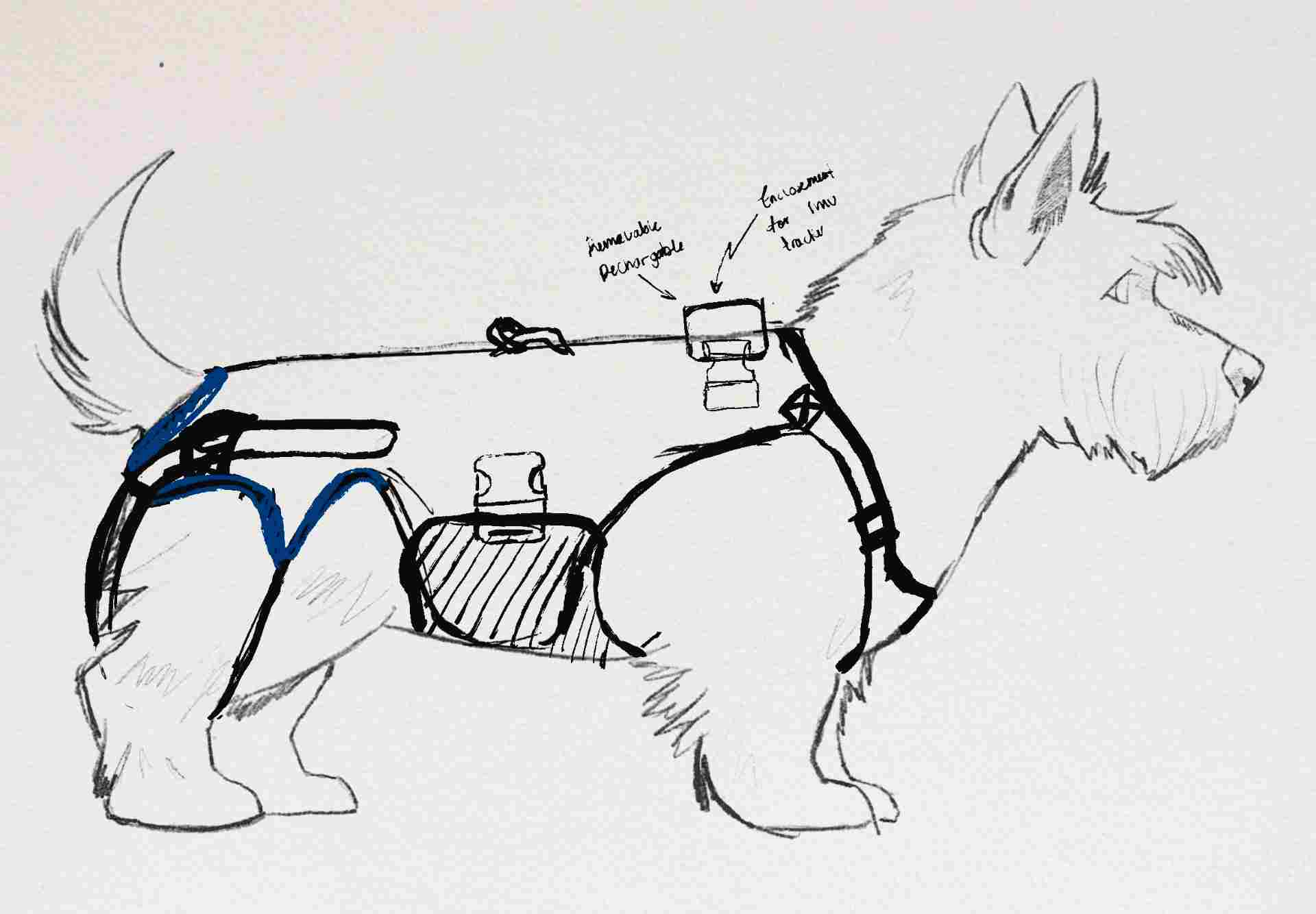
Sketching
Initial sketches
The sketching phase was about translating the concept into form — exploring how a brace could wrap around Krypto's body without restricting natural movement, while leaving space for the electronics module. The digital design process is documented in Week 2 → Computer Aided Design.
3D Scanning & Modeling
Scanning Krypto to build the base model
To build a brace that actually fits, I needed accurate geometry. I 3D scanned Krypto to generate a mesh of his body. The full scanning workflow is documented in Week 5 → 3D Scanning & Printing.
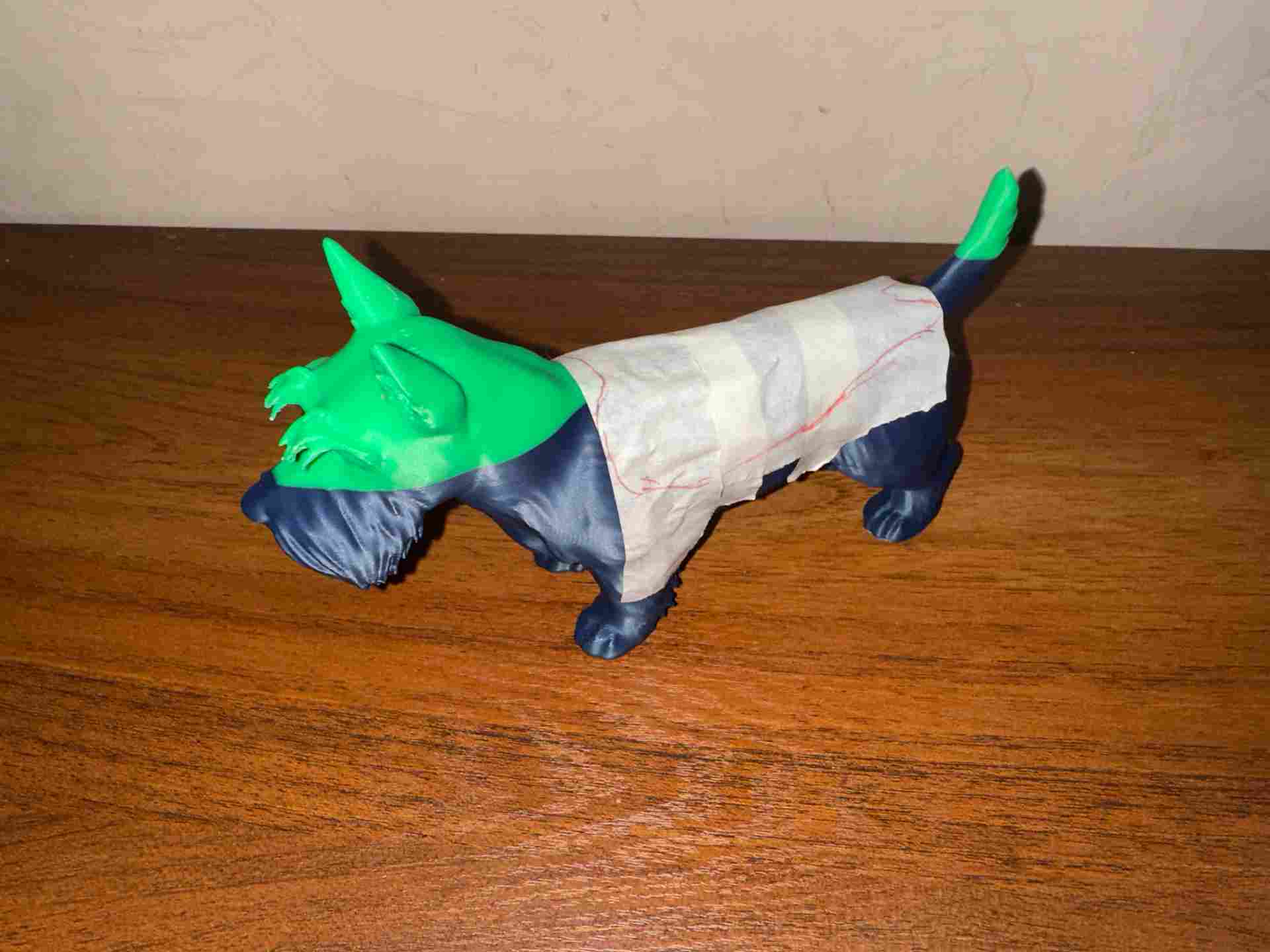
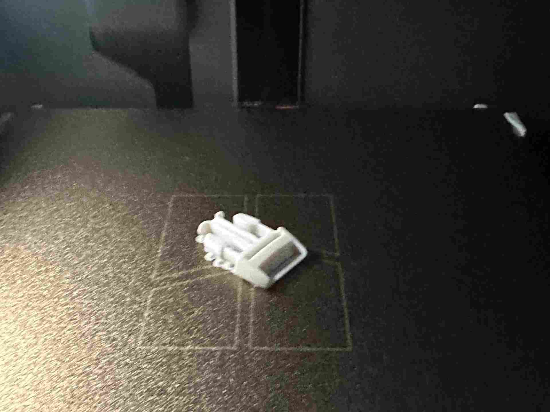
3D printing the reference model
With the scan processed, I printed a scaled physical model of Krypto's torso as a maquette for testing form and proportions.
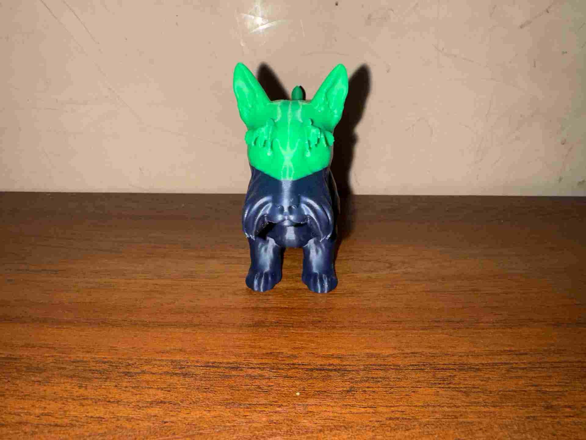
Printed maquette — front
Scale model used to test brace fit and pattern proportions.
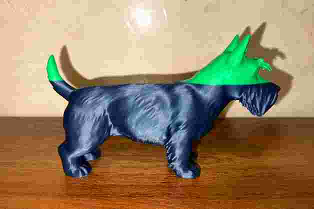
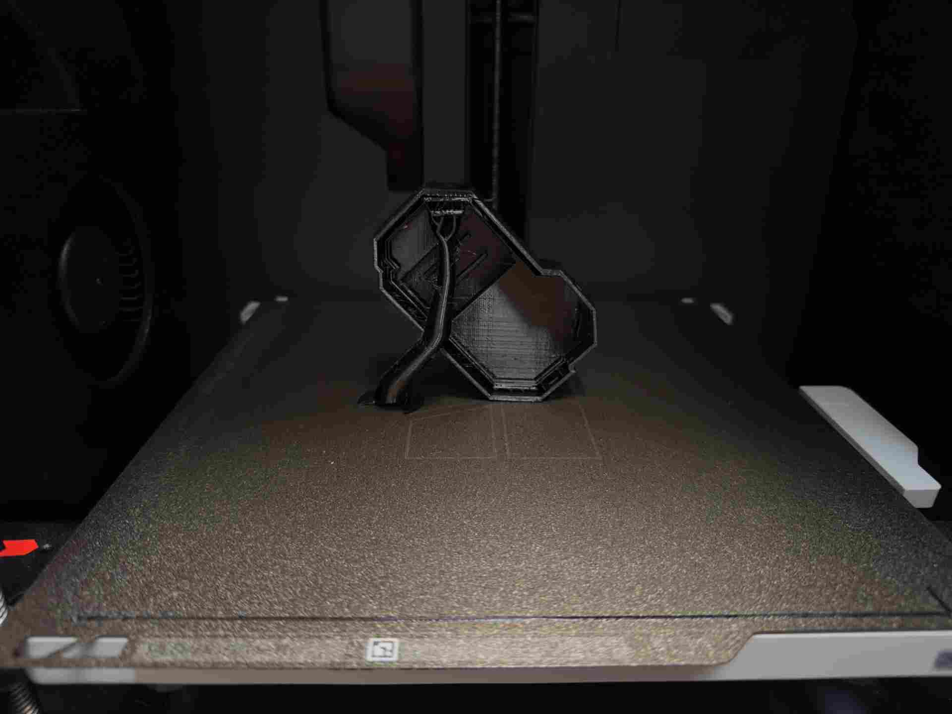
Printed maquette — side
Side view showing the hip geometry used for pad placement.
Pattern Making
From 3D model to flat pattern with masking tape
Wrapping the 3D print in masking tape, then cutting and flattening the tape to get the base pattern pieces. This technique reveals the true 2D geometry of a 3D surface without guessing.
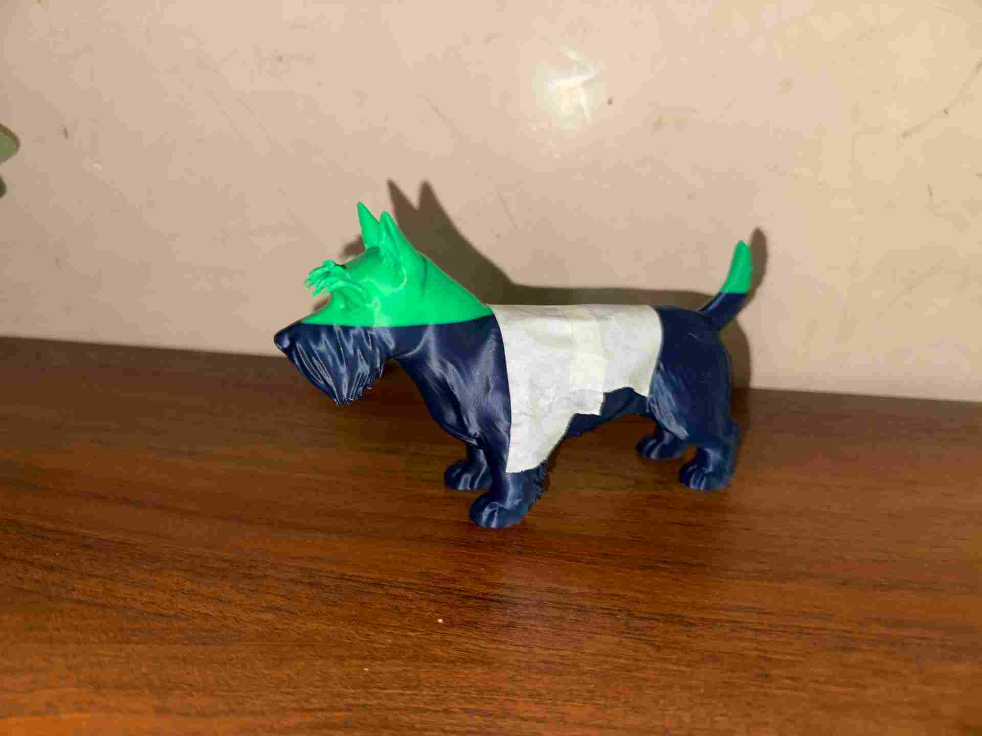
Wrapping the model
Masking tape applied directly over the 3D print.
Cutting the tape
Pattern pieces cut on the model, then removed and laid flat.
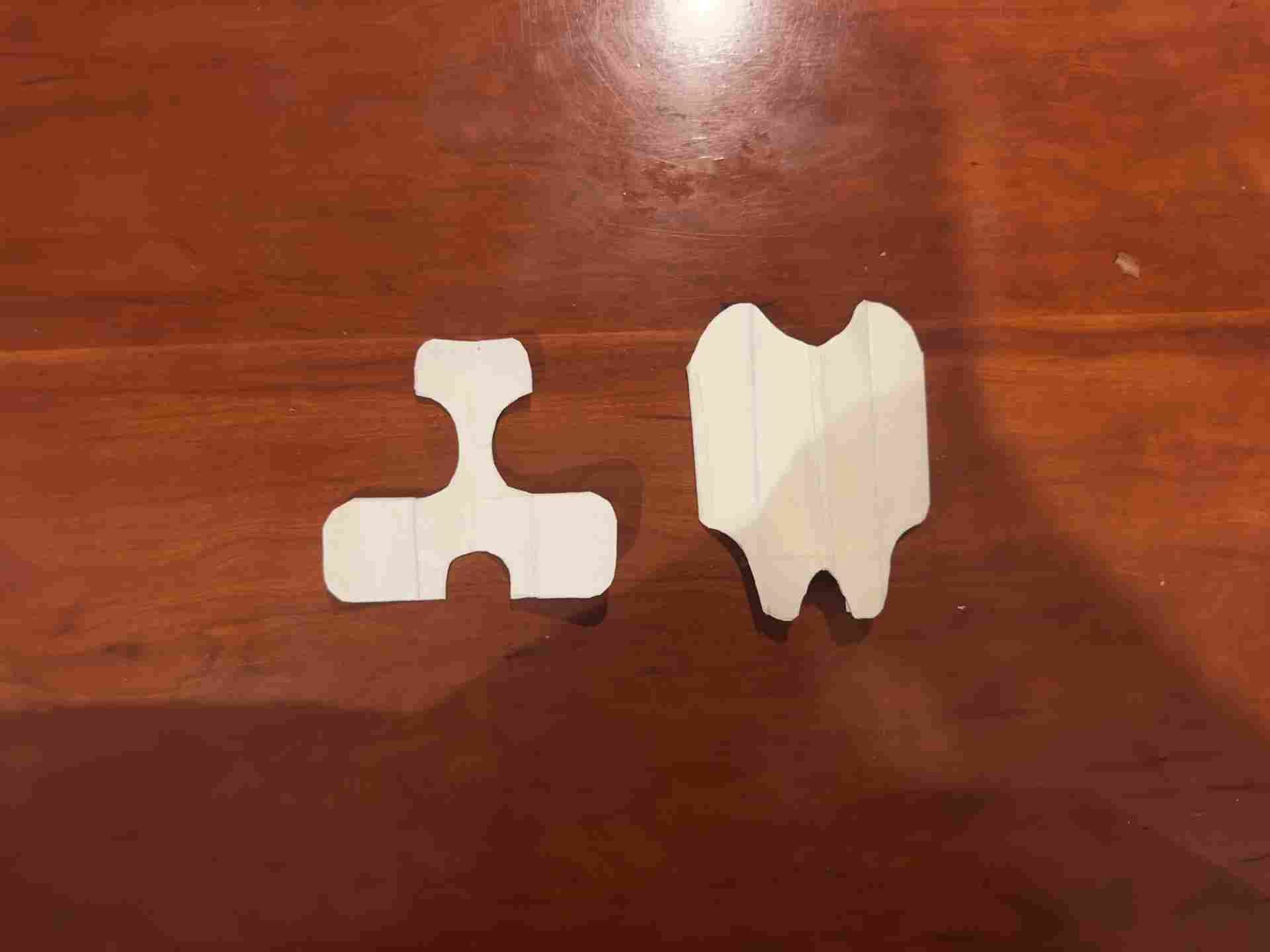
Flat pattern pieces
Each piece labeled and ready to import digitally.
Taking measurements from Krypto
Real measurements — chest circumference, torso length, hip width — taken directly from Krypto and compared against the tape pattern.
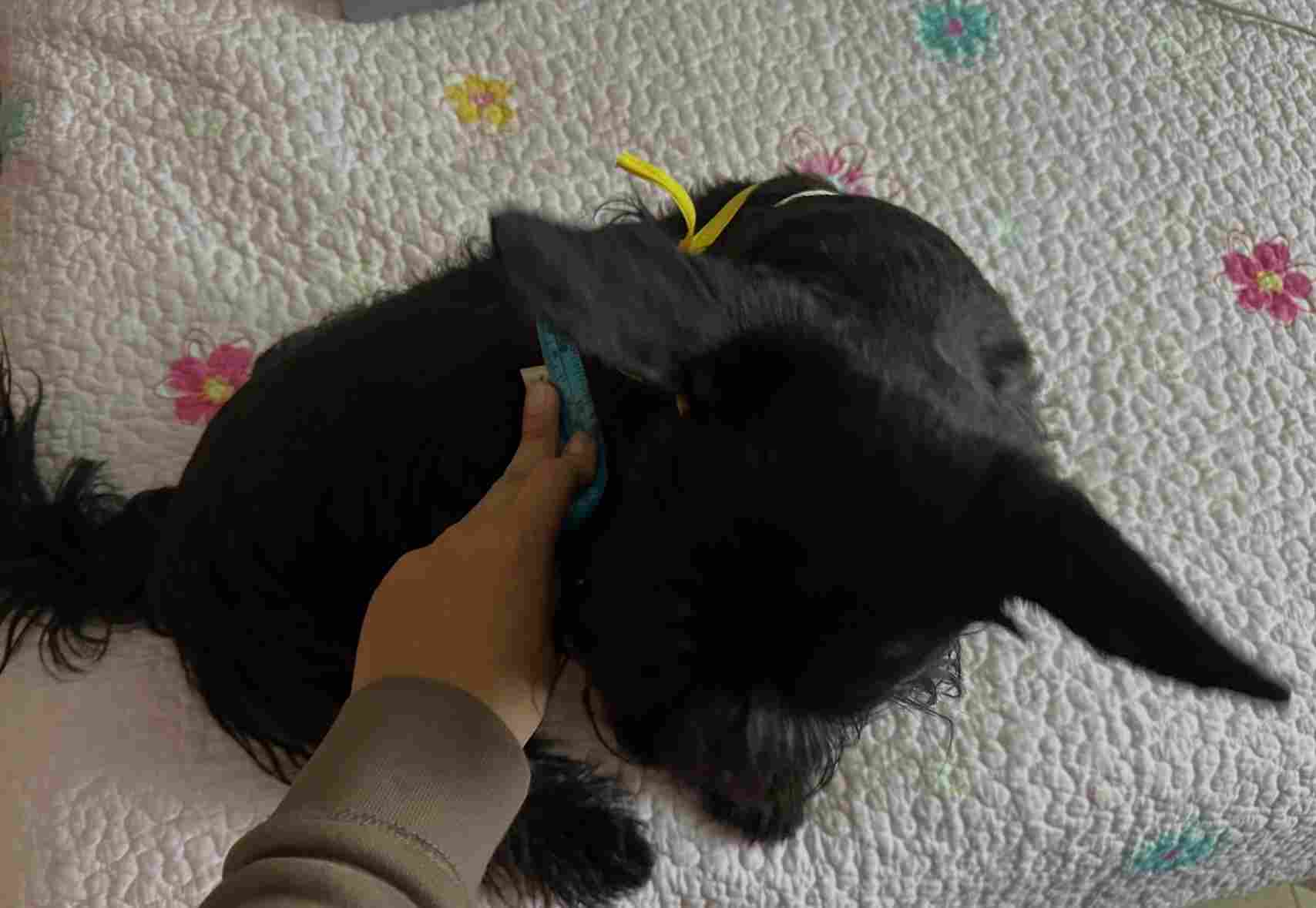
Measuring Krypto
Key body measurements taken with a soft measuring tape.
Digitizing patterns in Shapr3D
The flattened tape patterns were traced and redrawn in Shapr3D, where measurements were verified and curves refined.
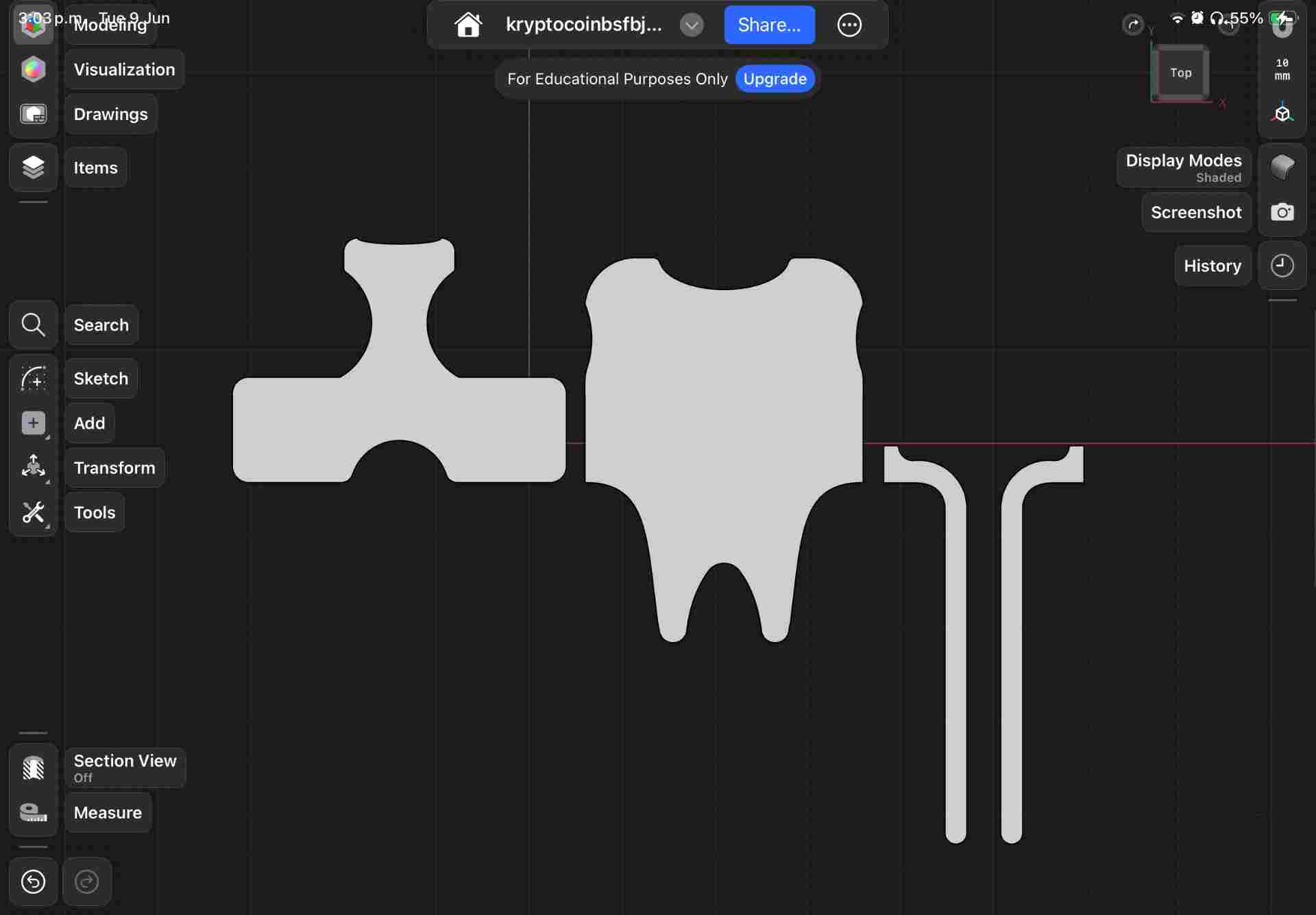
Pattern in Shapr3D
Tape shapes traced as closed sketches with exact dimensions.
Laser Cutting the Fabric
Cutting brace pieces on the laser cutter
Laser cutting fabric gives cleaner, sealed edges. Full workflow documented in Week 3 → Computer-Controlled Cutting.
| ⚡ Parameter | Value | Notes |
|---|---|---|
| Machine | CAMFive CO₂ | 60W CO₂ laser cutter |
| Material | Neoprene / fabric | 3mm thickness |
| Power | 35–25% | |
| Speed | 50 mm/s | |
| Passes | 1 | Single pass full cut |
| Air assist | ON | Prevents flare-up on fabric |
| Focus | Material surface | Set Z to top of fabric |
| File format | SVG / DXF | Exported from Shapr3D |
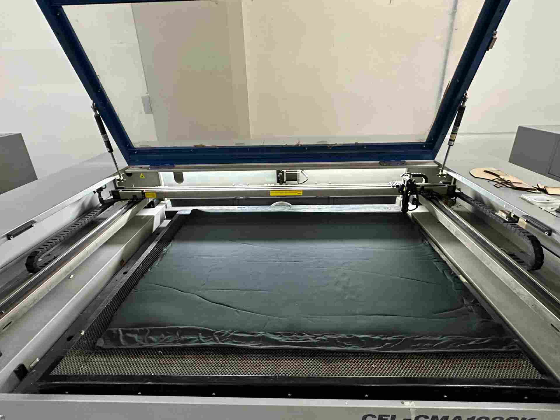
Setup
Fabric pinned flat to the cutting bed.
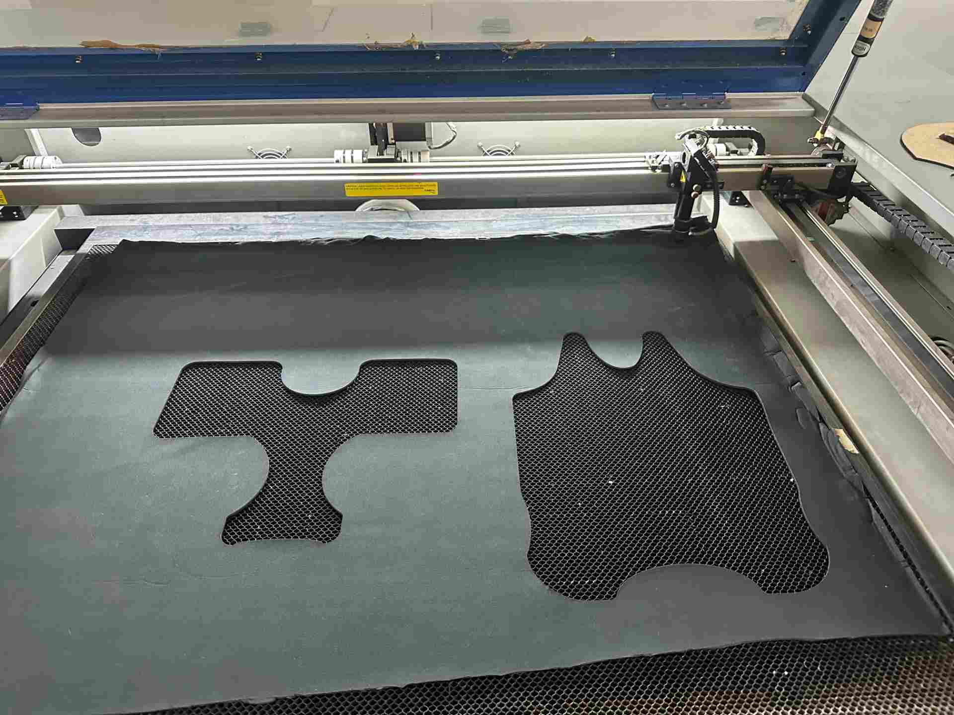
Cutting in progress
Laser tracing the pattern outline.
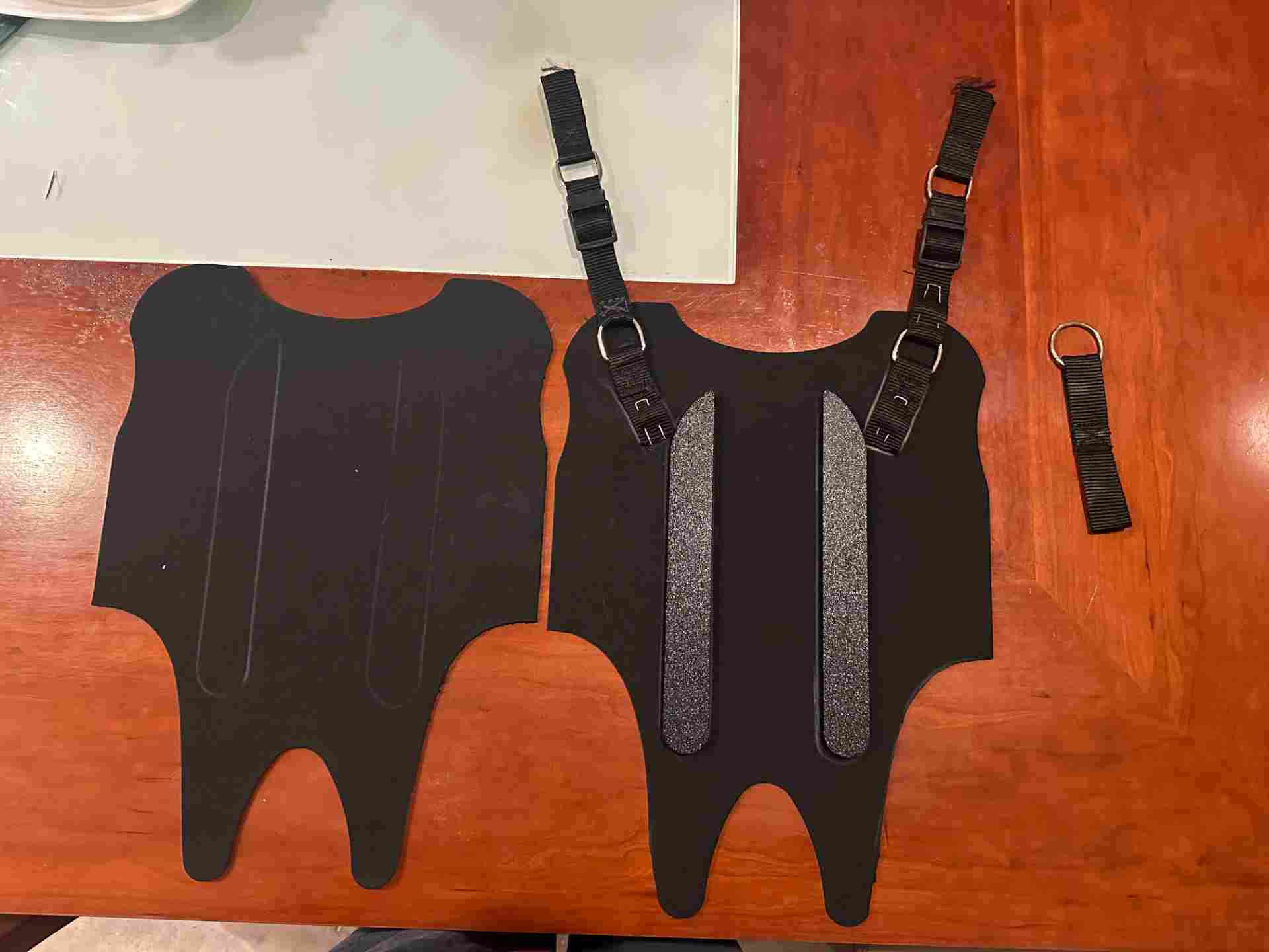
Cut pieces
Clean edges, no fraying.
PCB Design & Fabrication
Designing the schematic in KiCad 9
XIAO ESP32-C6 + MPU-6050 on a 60×40mm single-layer board. Schematic defines all connections: power rails, I²C lines, TP4056 battery management, decoupling capacitors, and power switch. The full electronics design process is documented in Week 6 → Electronics Design.
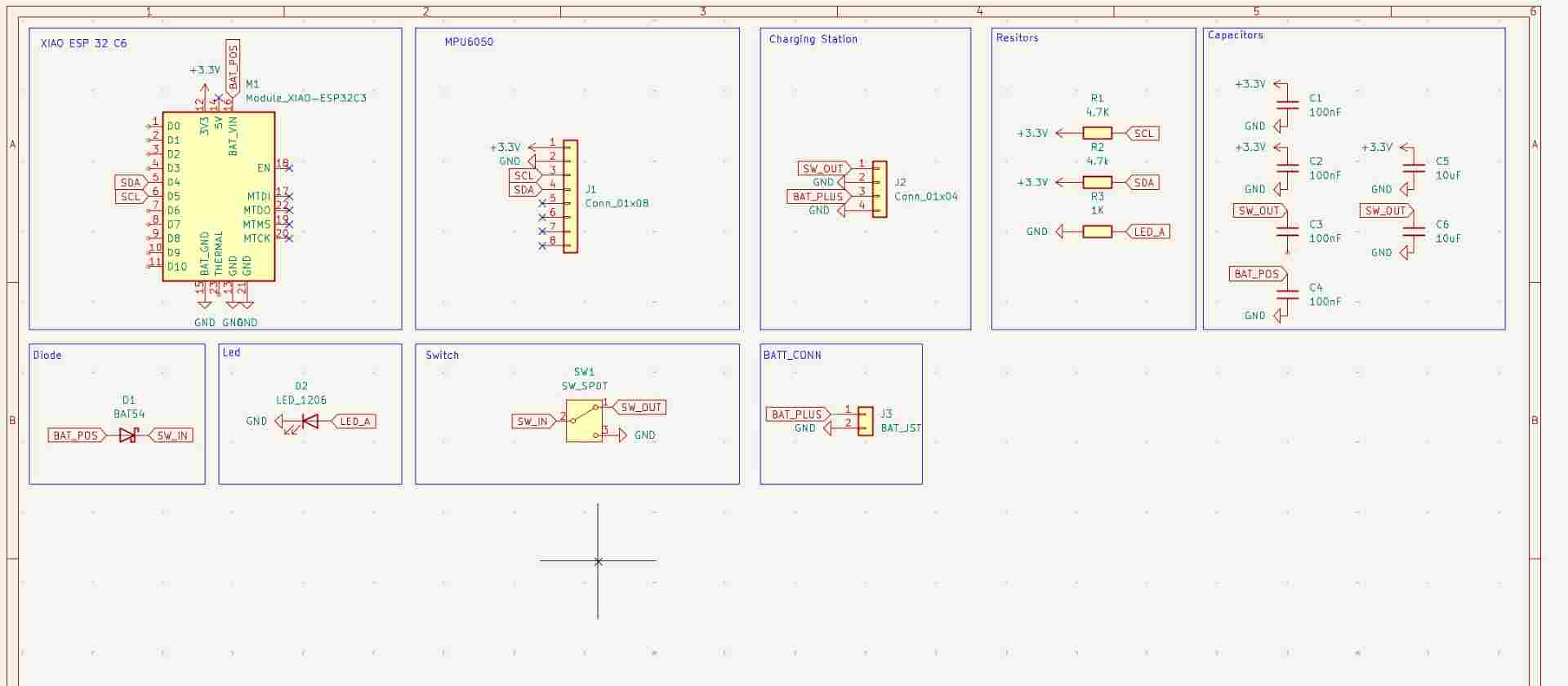
Schematic
Full schematic showing all component connections.
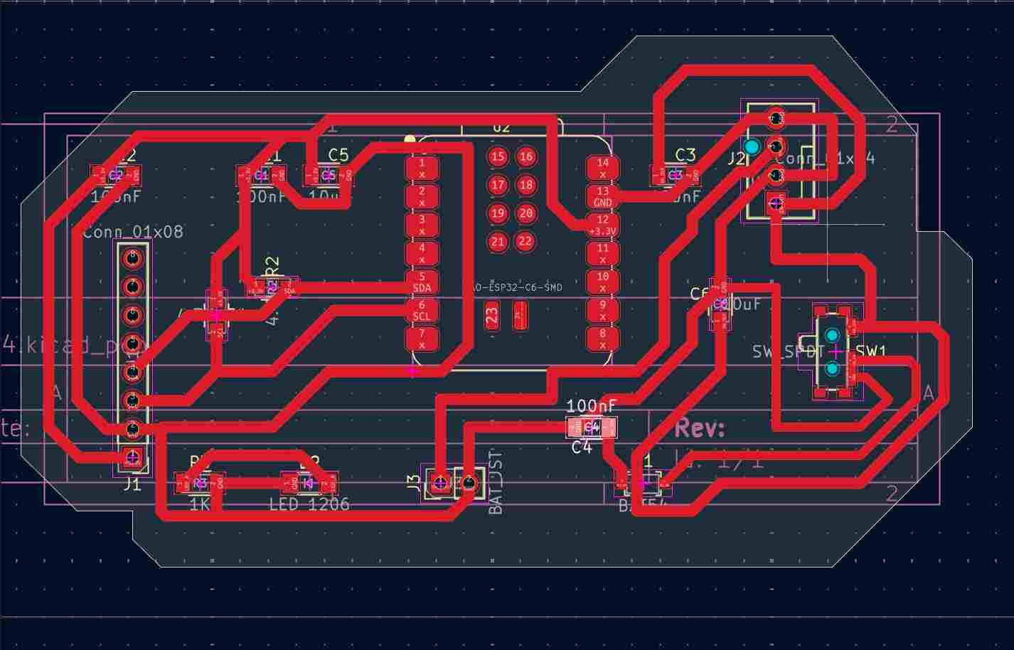
PCB Layout
60×40mm single-layer routed board.
Milling the PCB on the xTool F1 Ultra
- 1Export Gerbers from KiCad
Copper layer, board outline, drill file. DRC cleared before export. - 2Convert with FlatCAM
Isolation routing toolpaths for copper traces and cutout path for the outline. - 3Set up the xTool F1 Ultra
Copper-clad fixed with double-sided tape. Origin set to board corner. - 4Mill traces & cut outline
Isolation pass first, then board outline. Inspected with loupe. - 5Inspect & clean
Continuity checked with multimeter. Problem areas marked for rework.
| ⚡ Parameter | Value | Notes |
|---|---|---|
| Machine | xTool F1 Ultra | Diode + IR dual laser |
| Material | FR1 copper-clad, 1oz | Single-layer board |
| Power — trace | 100% | |
| Speed — trace | 750mm/s | |
| Passes — trace | 6 | |
| Speed — trace 2 | 450mm/s | |
| Passes — trace 2 | 10 | |
| Power — outline | 100% | |
| Speed — outline | 100mm/s | |
| Passes — cut | 21 | |
| File | G-code via FlatCAM | Isolation routing export |
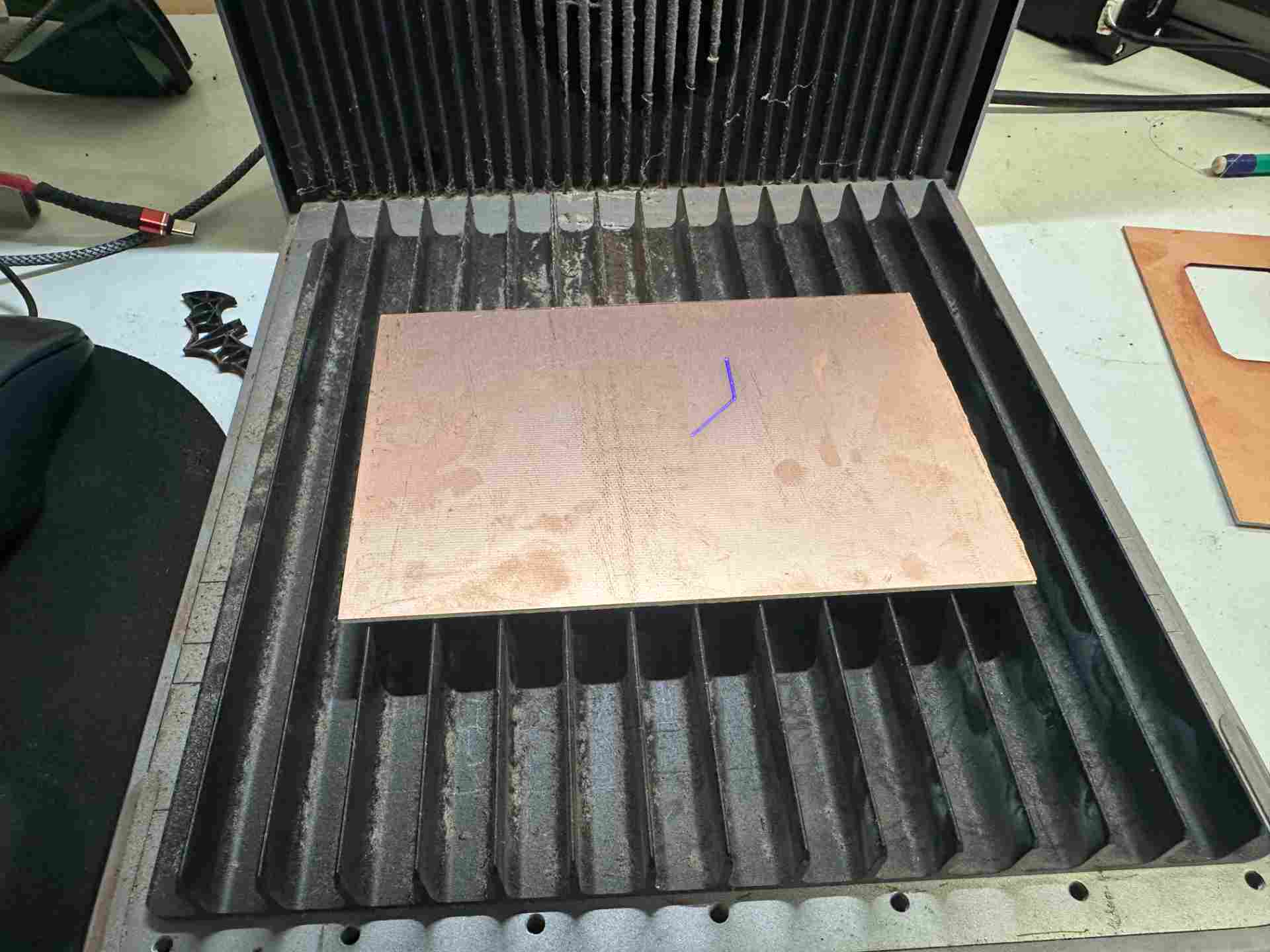
Board on the xTool bed
Copper-clad fixed and origin set.
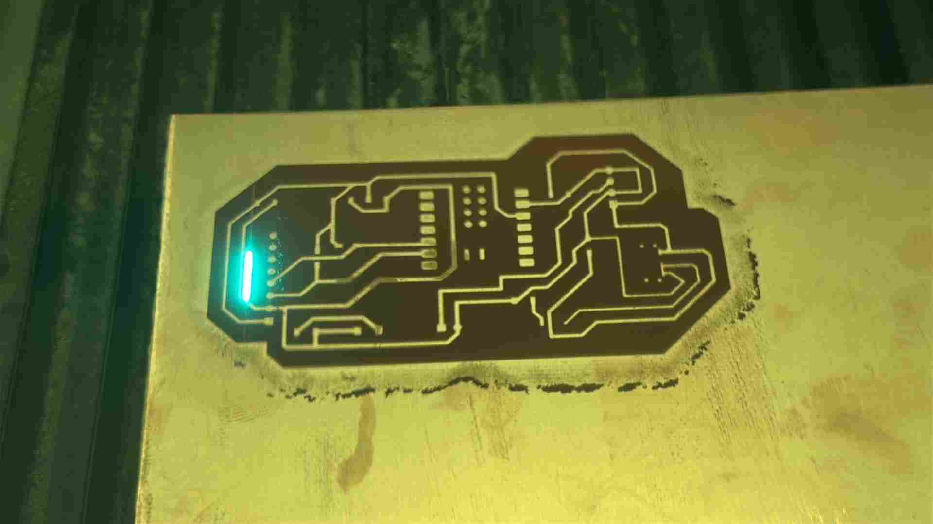
Milling in progress
Isolation pass carving copper traces.
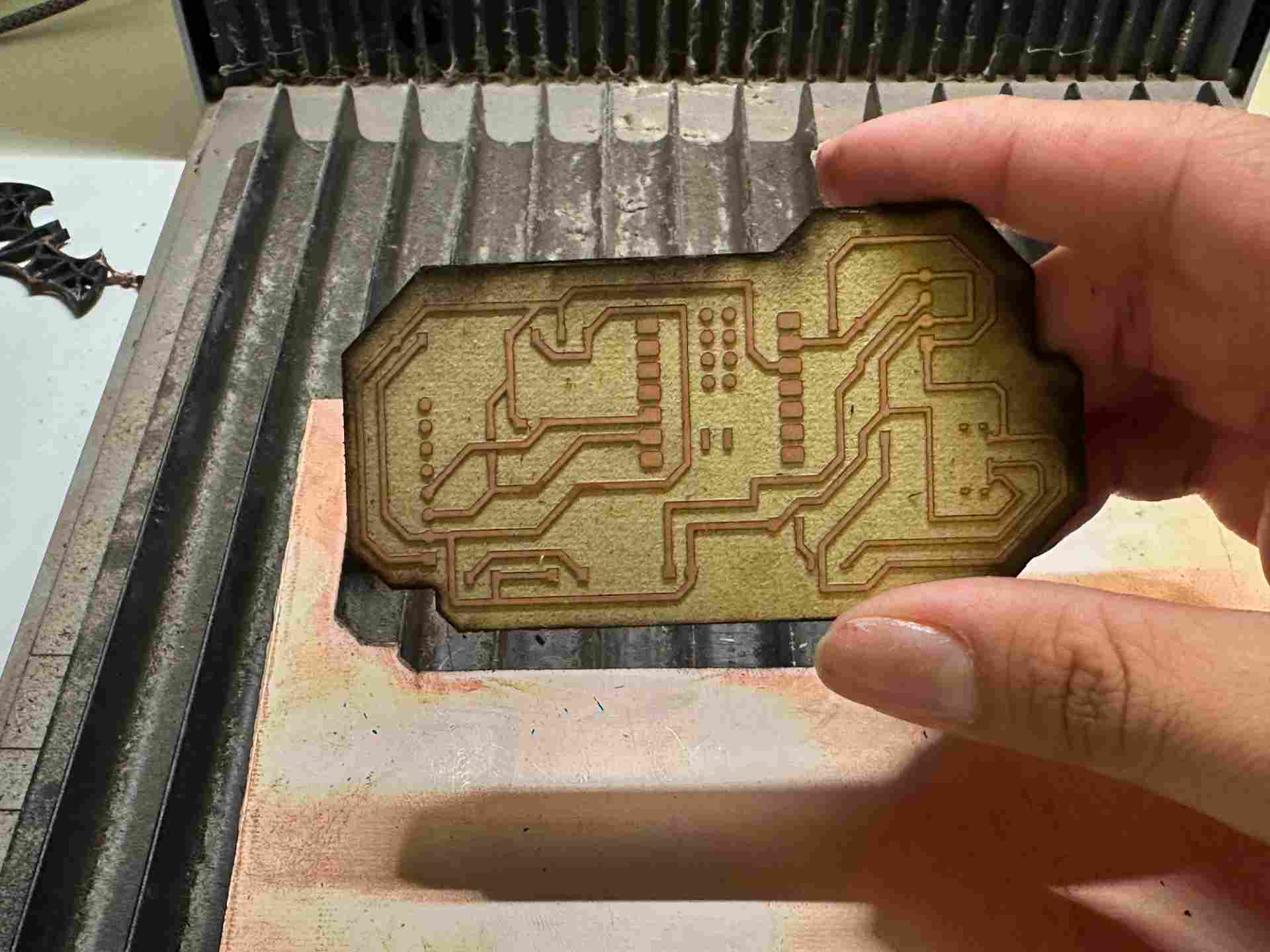
Finished board
Cleaned PCB inspected for defects.
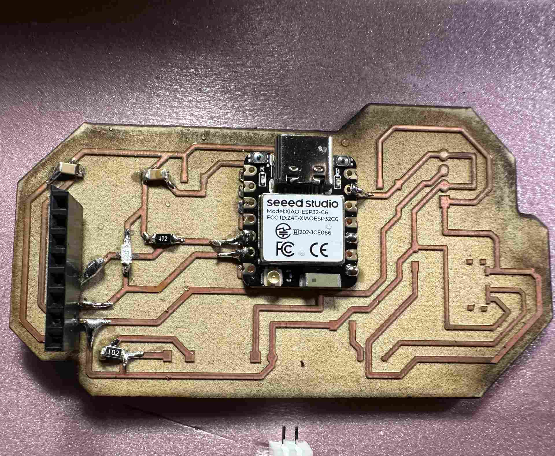
Soldering components
Started with smallest SMD parts (capacitors, resistors) and worked up to XIAO ESP32-C6 and MPU-6050. TP4056 module checked for damage before installation — one module found suspect and replaced. The full electronics production process is documented in Week 8 → Electronics Production.
SMD soldering
Passive components soldered first under magnification.
Fully assembled PCB
All components placed and soldered.
Firmware & Programming
Programming the board in Arduino
Firmware on XIAO ESP32-C6: MPU-6050 data acquisition, complementary filter for pitch/roll, activity/rest detection, spinal angle tracking, lateral asymmetry, restlessness scoring. Hosts a Wi-Fi web app with /datos, /reset, /calibrar from LittleFS. Embedded programming foundations are documented in Week 4 → Embedded Programming. The web interface was developed in Week 14 → Interface & Application Programming.
// ── Krypto Support — Main Firmware ──────────────────────────
// XIAO ESP32-C6 + MPU-6050  |  Fab Academy 2026

#include <Wire.h>
#include <WiFi.h>
#include <WebServer.h>
#include <LittleFS.h>
#include <MPU6050.h>

const char* SSID     = "KryptoSupport";
const char* PASSWORD = "krypto2026";
MPU6050 imu;
WebServer server(80);

float ax_off=0,ay_off=0,az_off=0,gx_off=0,gy_off=0,gz_off=0;
float pitch=0,roll=0,spinalAngle=0;
bool  isActive=false;
unsigned long lastMotionTime=0;
int   postureChanges=0;

void setup(){
  Serial.begin(115200); Wire.begin(); imu.initialize(); LittleFS.begin();
  calibrate();
  WiFi.softAP(SSID,PASSWORD);
  server.on("/datos",handleDatos); server.on("/reset",handleReset);
  server.on("/calibrar",handleCalibrar); server.onNotFound(serveFile);
  server.begin();
}

void loop(){ server.handleClient(); readAndFilter(); detectActivity(); delay(20); }

void readAndFilter(){
  int16_t ax,ay,az,gx,gy,gz;
  imu.getMotion6(&ax,&ay,&az,&gx,&gy,&gz);
  float axF=ax/16384.0-ax_off, ayF=ay/16384.0-ay_off, azF=az/16384.0-az_off;
  float gxF=gx/131.0-gx_off,   gyF=gy/131.0-gy_off;
  float accelPitch=atan2(ayF,azF)*180.0/PI;
  float accelRoll =atan2(-axF,azF)*180.0/PI;
  const float dt=0.02,alpha=0.98;
  pitch=alpha*(pitch+gxF*dt)+(1-alpha)*accelPitch;
  roll =alpha*(roll +gyF*dt)+(1-alpha)*accelRoll;
  spinalAngle=abs(pitch);
}

void detectActivity(){
  bool motion=(spinalAngle>5.0||abs(roll)>5.0);
  if(motion){ if(!isActive){isActive=true;postureChanges++;} lastMotionTime=millis(); }
  else if(millis()-lastMotionTime>3000){ isActive=false; }
}

void calibrate()     { /* average 500 samples at rest */ }
void handleDatos()   { /* JSON: pitch, roll, angle, active, changes */ }
void handleReset()   { /* reset postureChanges */ }
void handleCalibrar(){ /* trigger recalibration */ }
void serveFile()     { /* serve LittleFS files */ }
Enclosure & Hardware Design
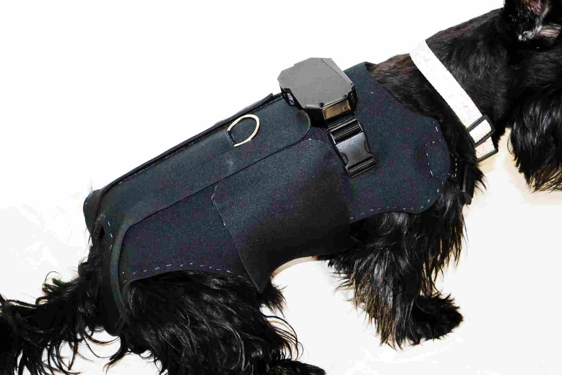
Designing the PCB enclosure and hip supports
Electronics housing snaps onto the fabric strap, protects the PCB, and allows access to USB-C. Hip supports are anatomical pads to distribute pressure evenly.
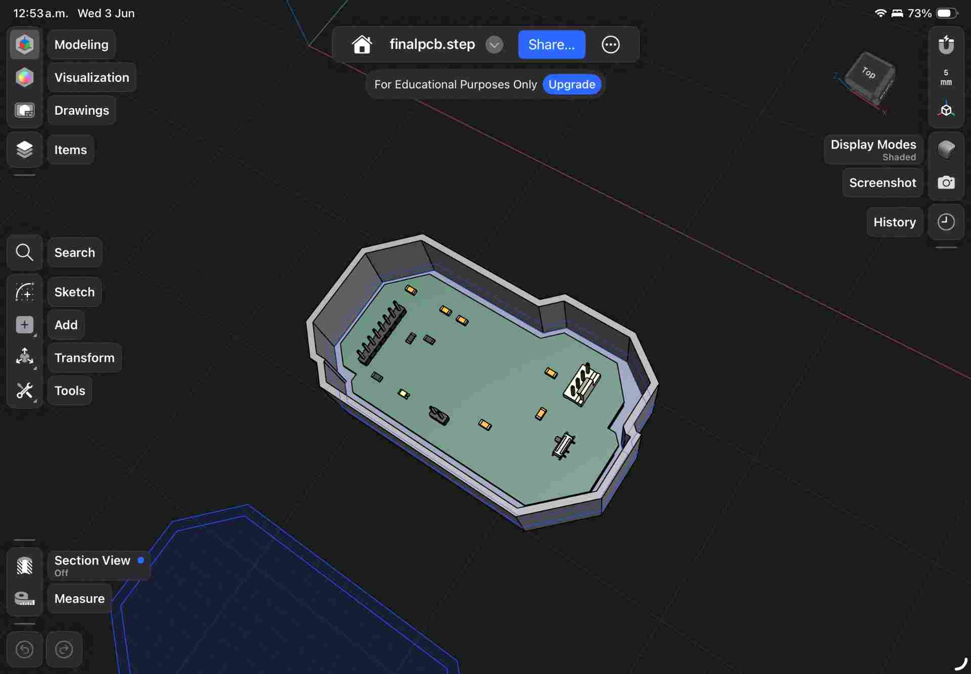
PCB enclosure design
Press-fit lid with USB-C and switch cutouts.
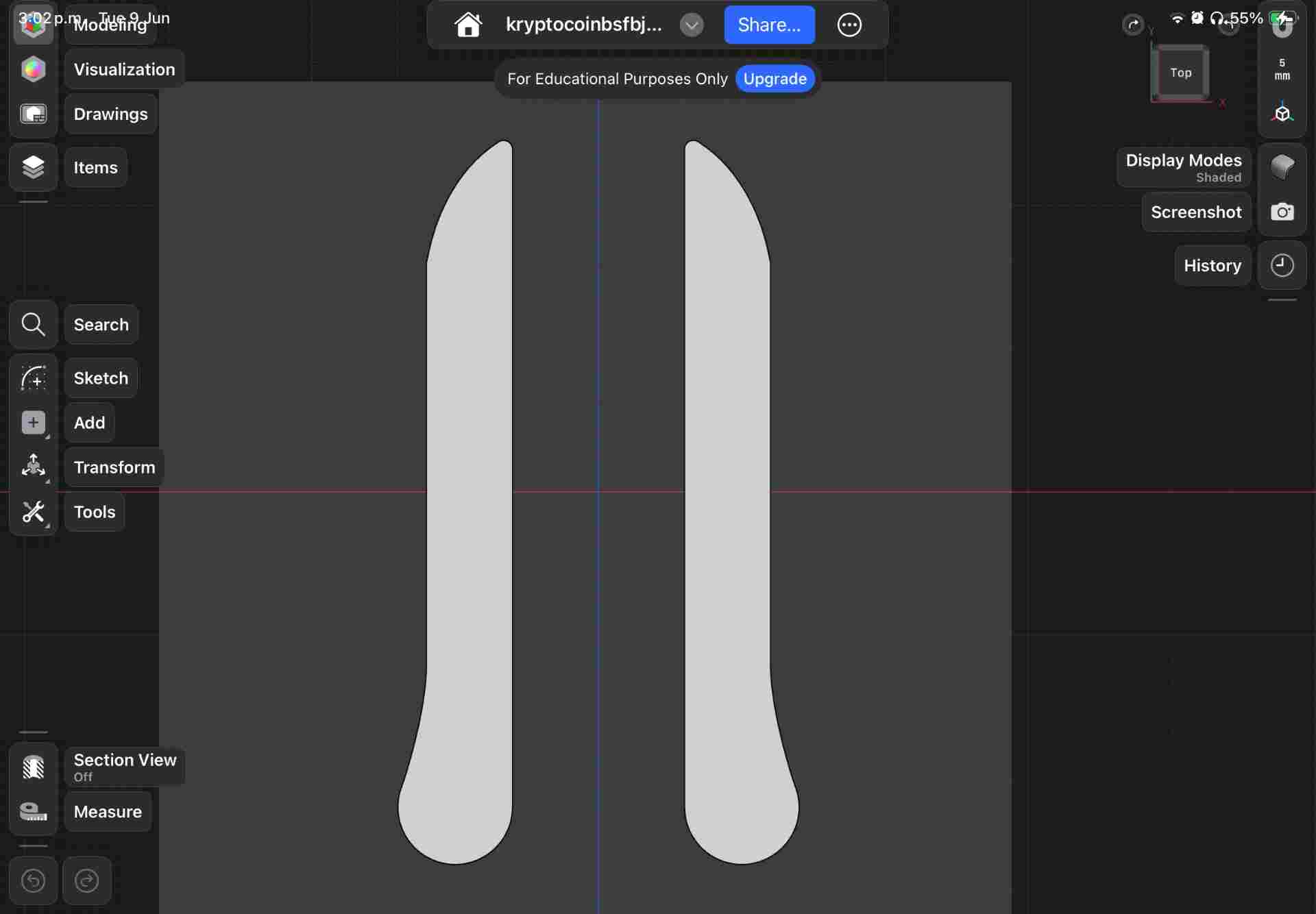
Hip support pads
Anatomical geometry following Krypto's hip contour.
3D Printing: buckles, enclosure, and hip supports
Quick-Release Buckles — ABS
First designed in Week 2 → Computer-Controlled Cutting, refined for final build.
PCB Enclosure — TPU
Press-fit lid with USB-C and switch ports.
Hip Supports — TPU
Flexible pads, 95A shore hardness.
Logo Design
Two versions of the Krypto Support identity
Two logo variants developed at different points for the packaging and web dashboard.
Version 1 — designed in Week 14 → Interface & Application Programming
Version 2 — final version for packaging
Logo design timelapse:
Packaging
Box design in Illustrator & visualization in Packdora
Designed in Illustrator, visualized in Packdora, then cut on the laser cutter. Tab-and-slot construction — no glue required.
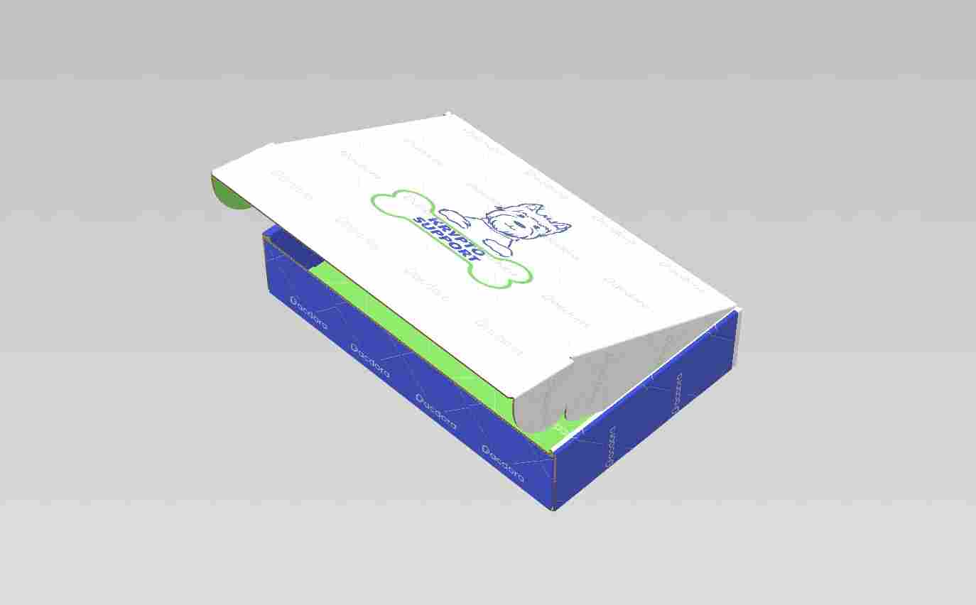
Packdora visualization
3D preview before cutting any material.
Assembled box
Final box from the laser-cut pieces.
Laser cutting the packaging box
| ⚡ Parameter | Value | Notes |
|---|---|---|
| Machine | CAMFive CO₂ | 60W CO₂ laser cutter |
| Material | Kraft board | 2mm thickness |
| Power — cut | 35% | |
| Speed — cut | 400 mm/s | |
| Passes | 1 | Adjust per board thickness |
| Air assist | ON | Prevents scorching edges |
| File format | AI / SVG | Exported from Illustrator |
Vinyl logo cut & application
The final logo was cut in vinyl and applied to the assembled box.
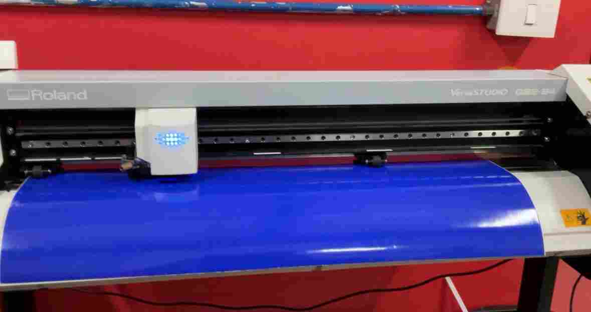
Vinyl cut
Logo cut on the vinyl cutter and weeded.

Logo applied
Transfer tape used to place the vinyl on the box face.
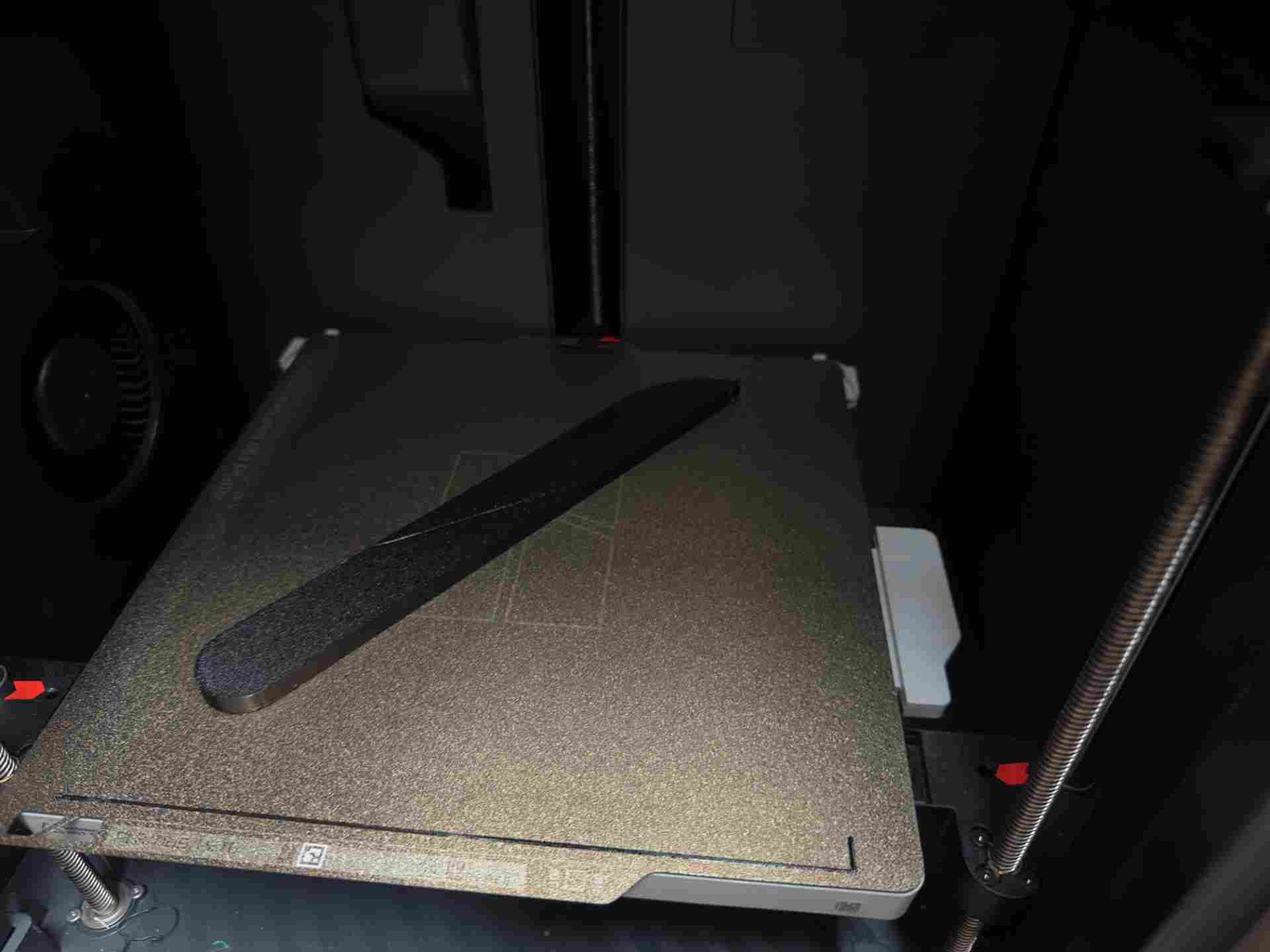
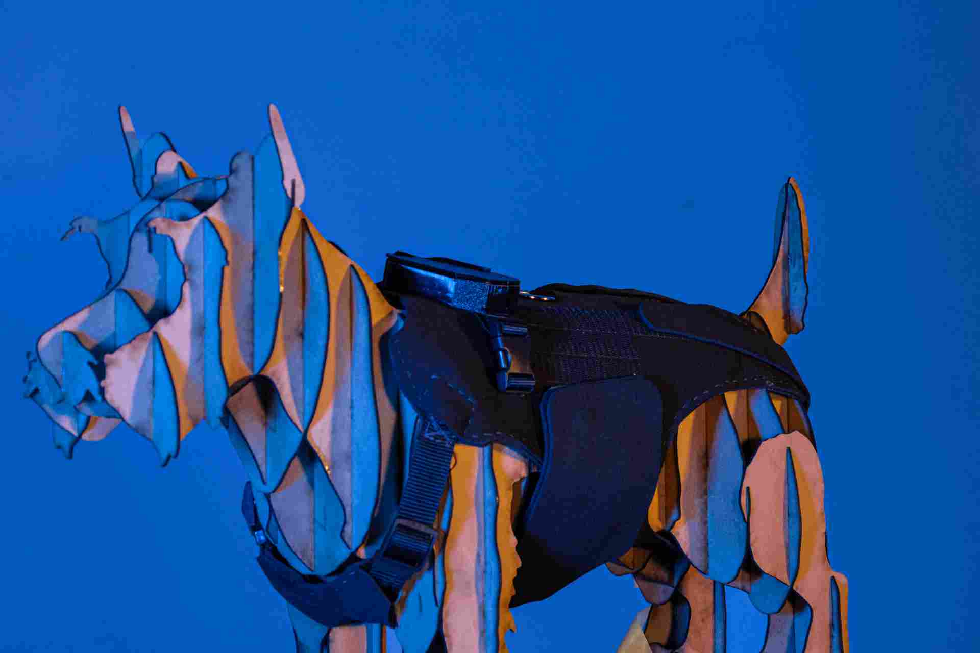
Photoshoot Model
Stereotomy model for product photography
Physical display model using stereotomy. Geometry prepared in Fusion 360, sliced with Slicer 360 for Fusion into stackable flat sections, assembled into a rigid sculptural form. 3D printing process and settings are documented in Week 5 → 3D Scanning & Printing.
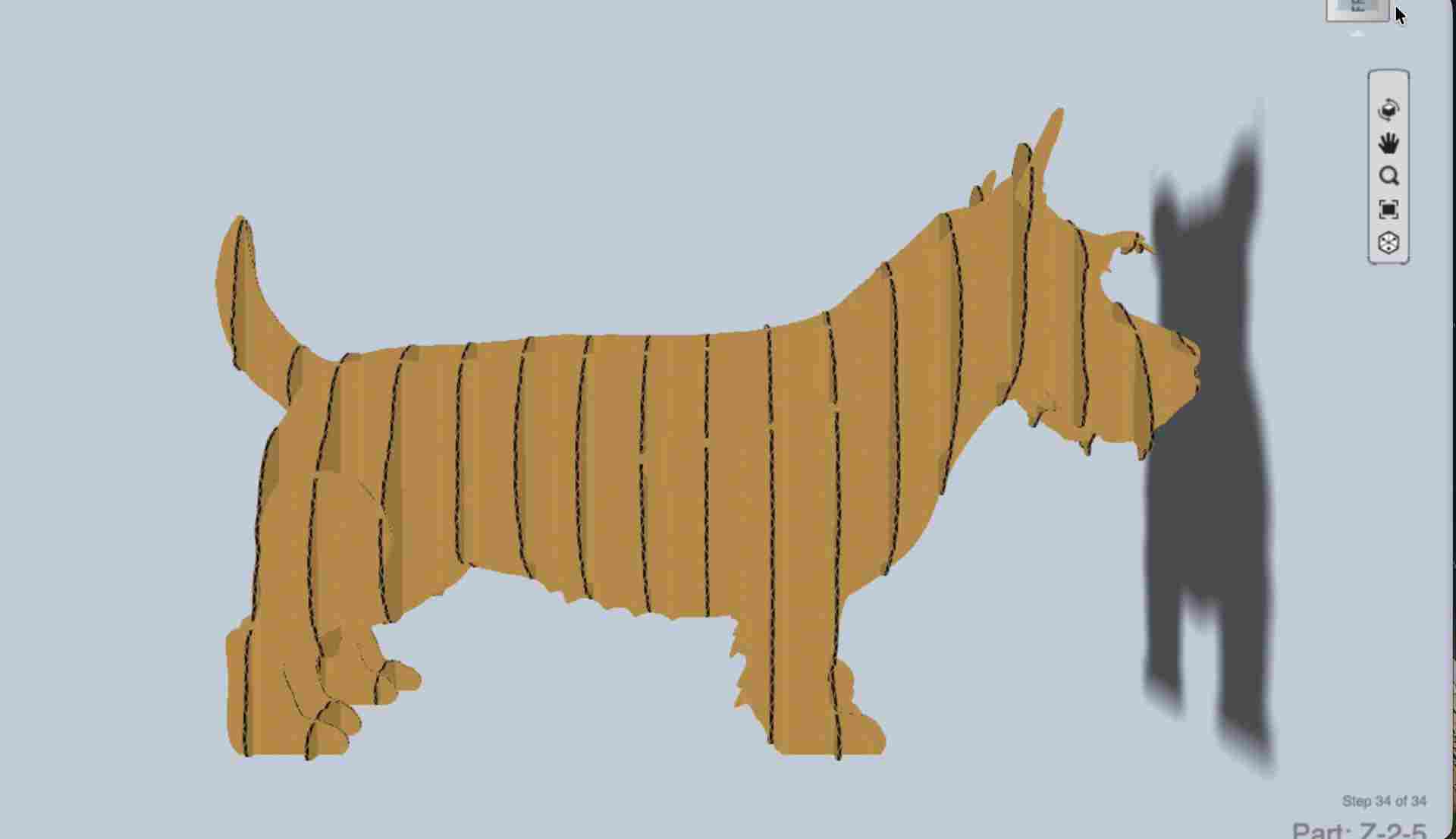
Slicer 360 sections
Fusion model sliced into flat interlocking layers.
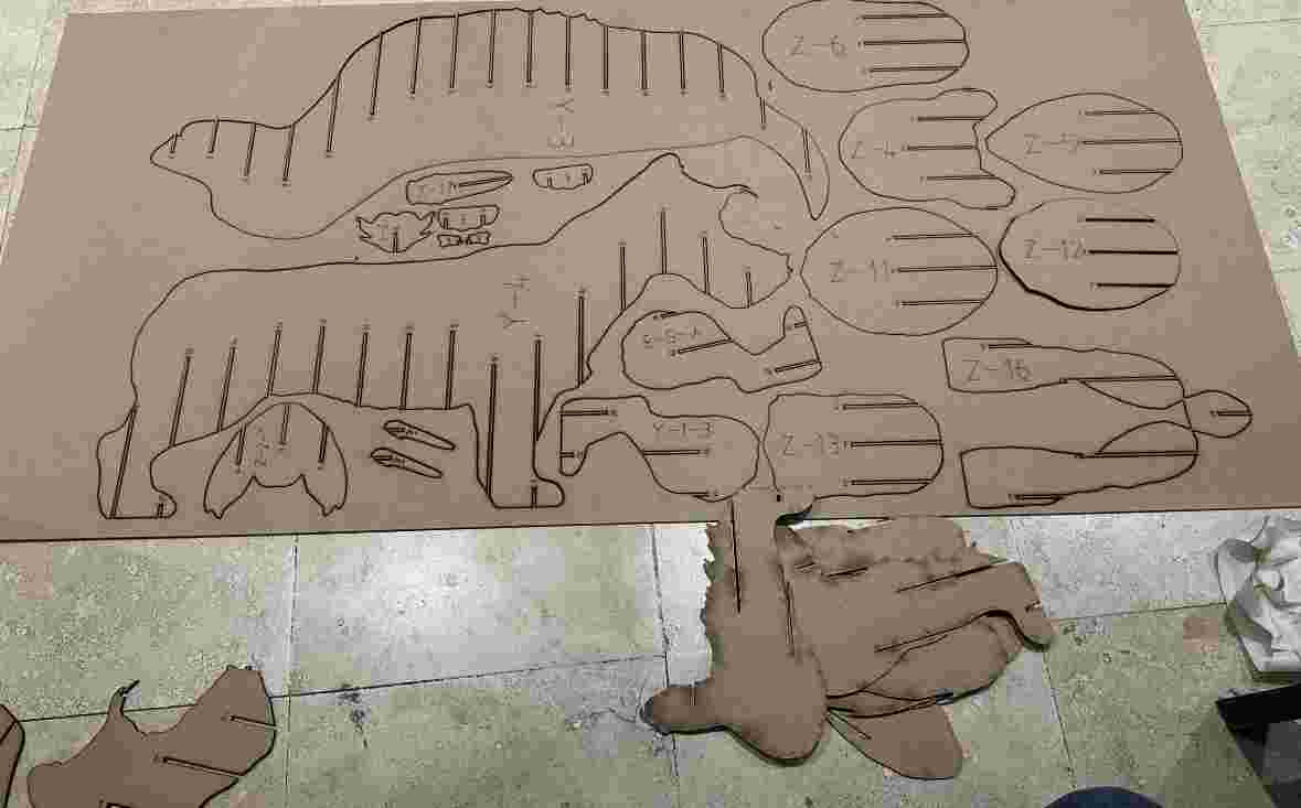
Assembly
Sections stacked and glued.
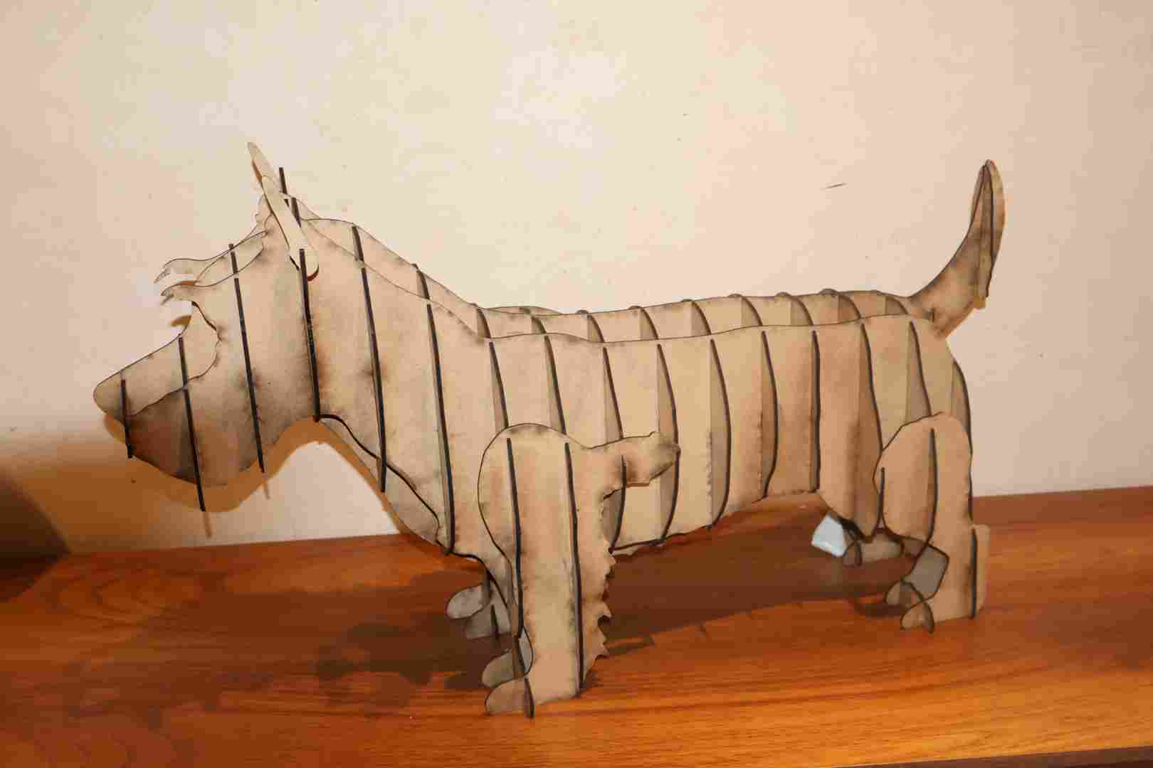
Finished model
Used as stand-in for product photography.
Testing
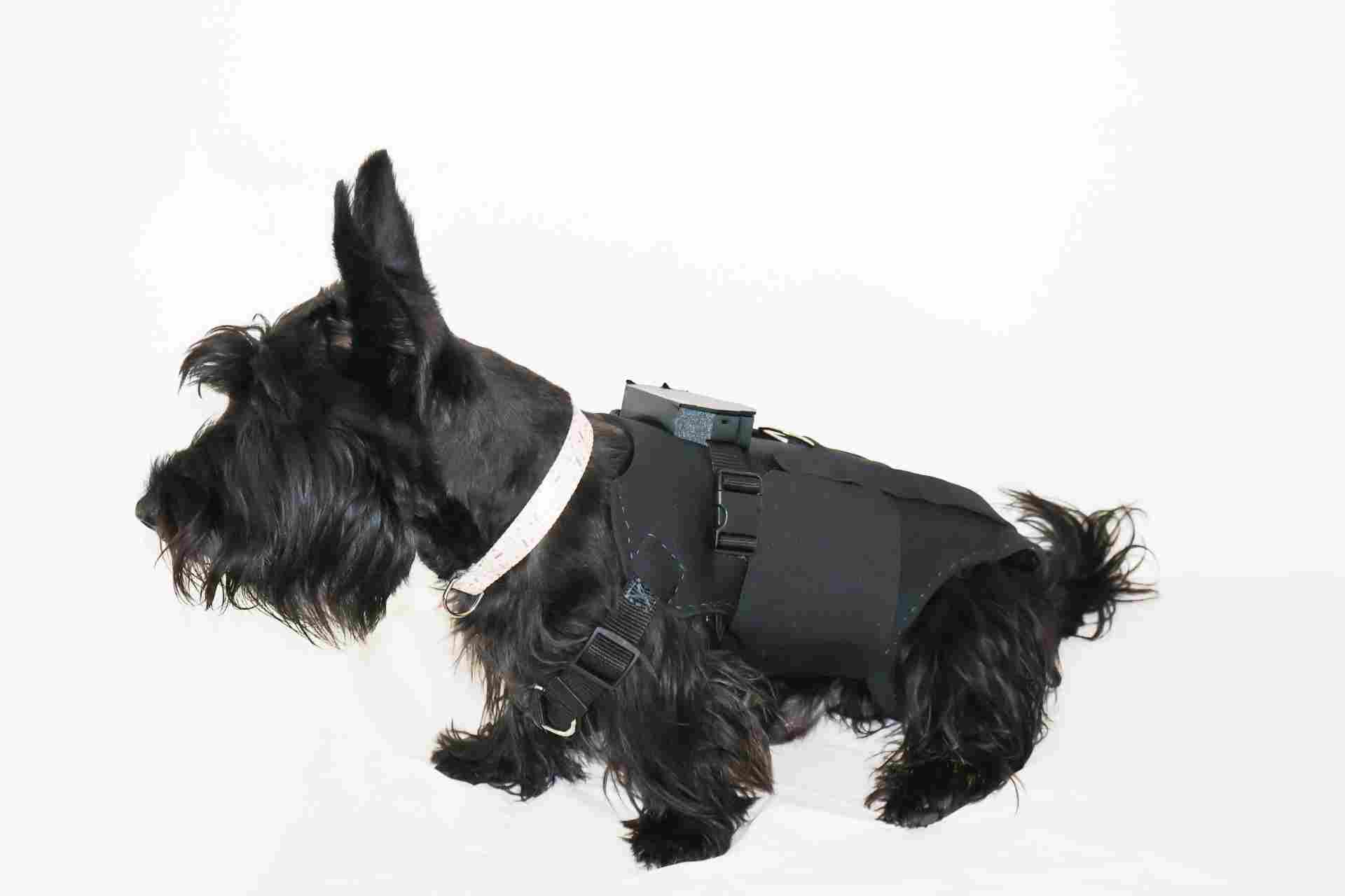
Brace fit test
First fit test on Krypto — buckles, hip pad alignment, gait check. Adjustments made to strap length and pad positioning.
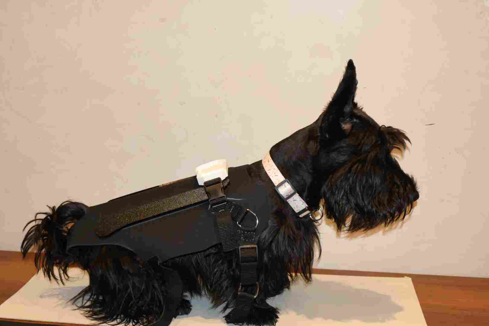
First fitting
Brace placed on Krypto to verify fit and buckle alignment.
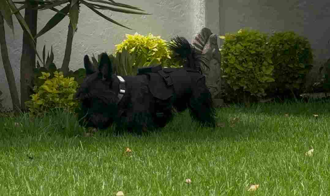
Gait check
Walking test to confirm no gait restriction.
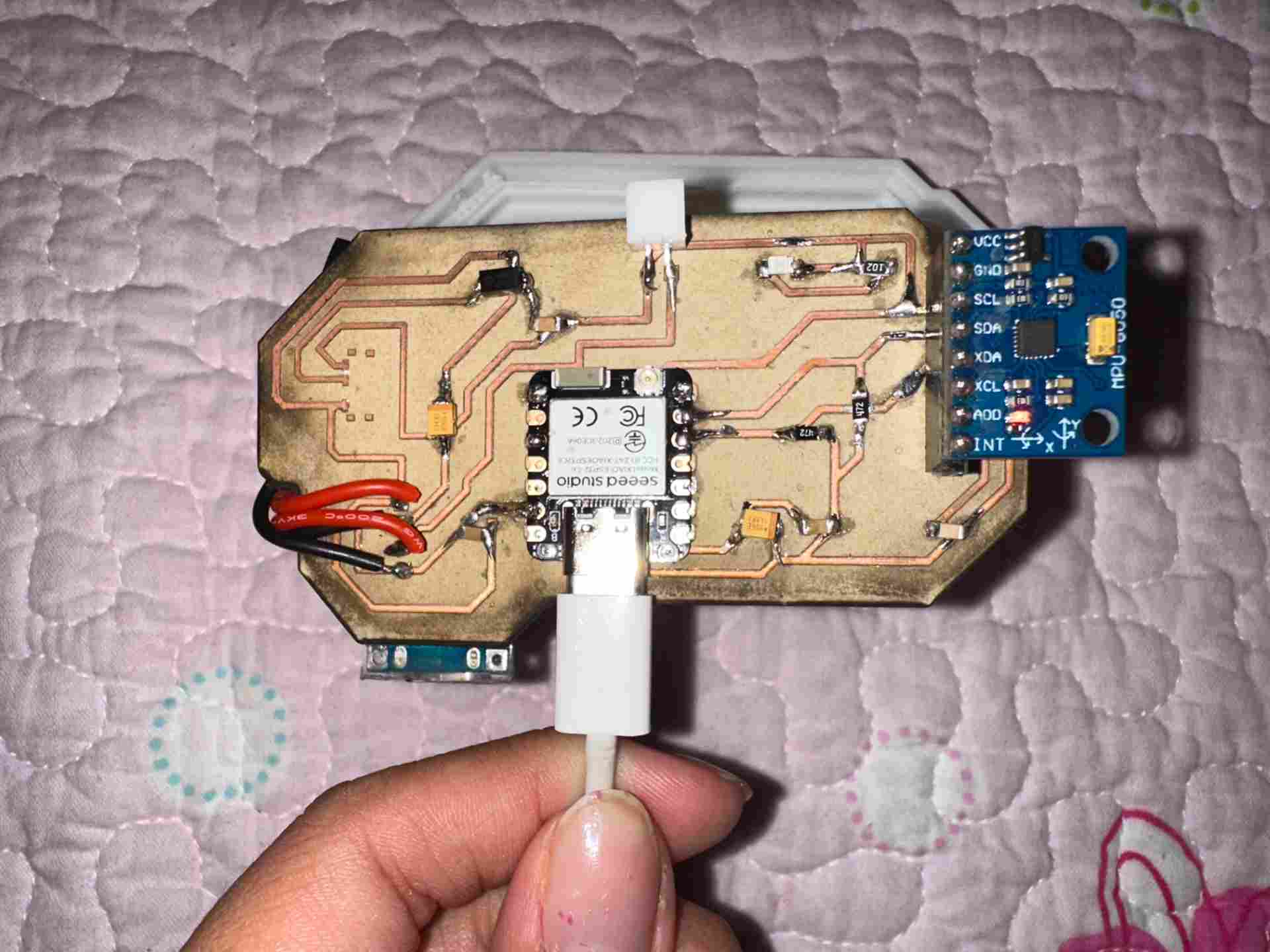
PCB & web app testing
Board powered up with MPU-6050 connected, serial output monitored to verify calibration and filter output. Dashboard accessed from a phone over the ESP32's Wi-Fi AP, confirming real-time updates on /datos and responsive controls. Networking and communication setup is documented in Week 11 → Networks & Communications.
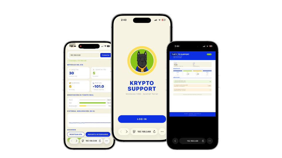
Web dashboard
Dashboard loaded on a phone over the ESP32's Wi-Fi AP.
Live demo
Real-time data updates and recalibration trigger tested on device.
From sensor data to veterinary report
The web app translates raw MPU-6050 readings into a structured PDF report that a veterinarian can read without interpreting sensor data. Activity level, impact events, spinal angle deviations, and postural asymmetry are converted into clinical language with actionable recommendations.
How the report is generated
The ESP32-C6 firmware accumulates MPU-6050 readings throughout the session — pitch, roll, spinal angle, impact events, and time spent in movement vs. rest. When the user taps "Generate PDF" in the app, those values are sent to the /datos endpoint, interpreted against predefined clinical thresholds, and formatted into a downloadable PDF.
The document converts raw numbers into clinical language: an acceleration peak > 2g is logged as "high-intensity impact", a sustained lateral deviation > 8° is reported as "postural compensation". The veterinarian receives actionable context, not raw sensor output.
Results
Fit
Fits Krypto's anatomy without limiting gait. Quick-release buckles allow one-handed on/off.
Data
MPU-6050 captures pitch, roll, and spinal angle. Dashboard updates in real time over Wi-Fi.
Battery
TP4056 allows USB-C charging without removing the electronics module.
Final photos
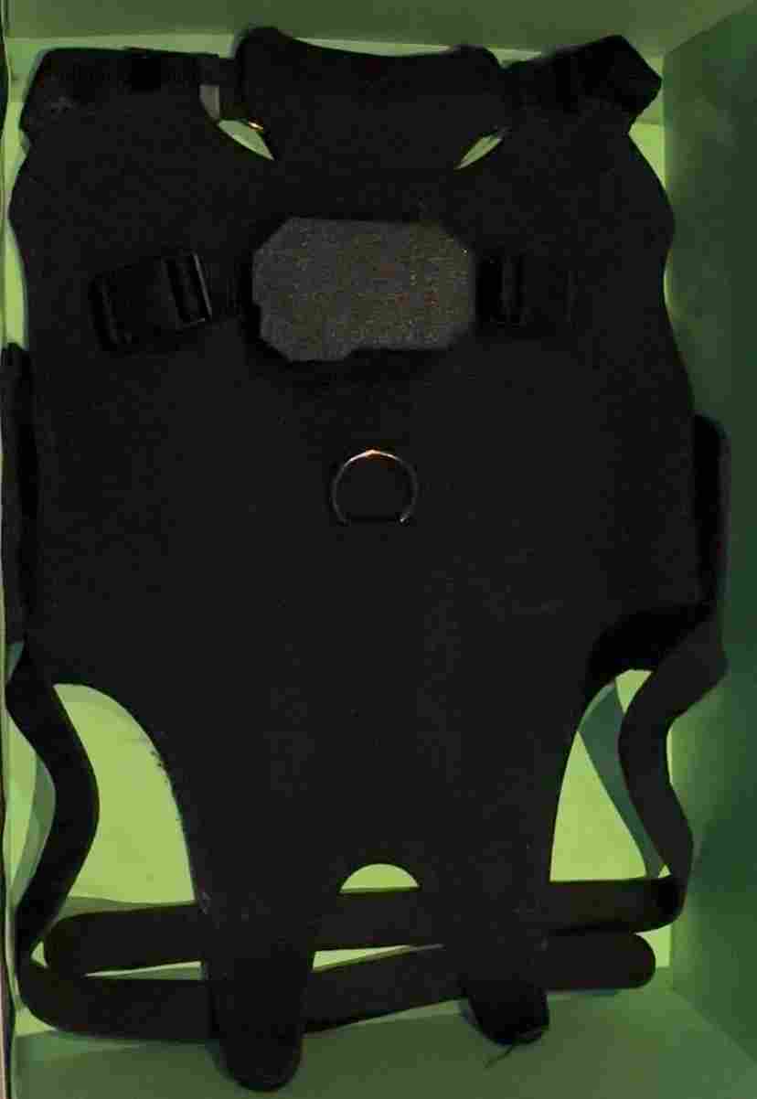
Final product
Assembled brace with all components integrated.
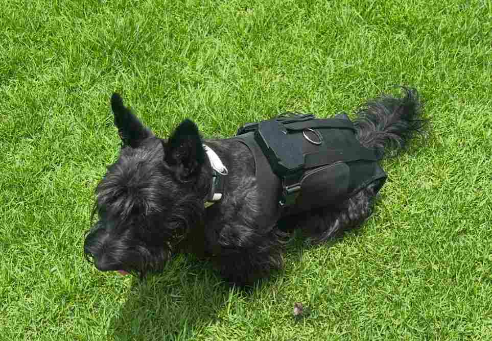
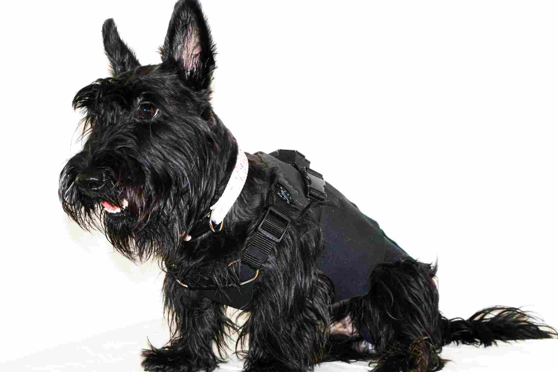
On Krypto
Brace worn by Krypto during final testing session.
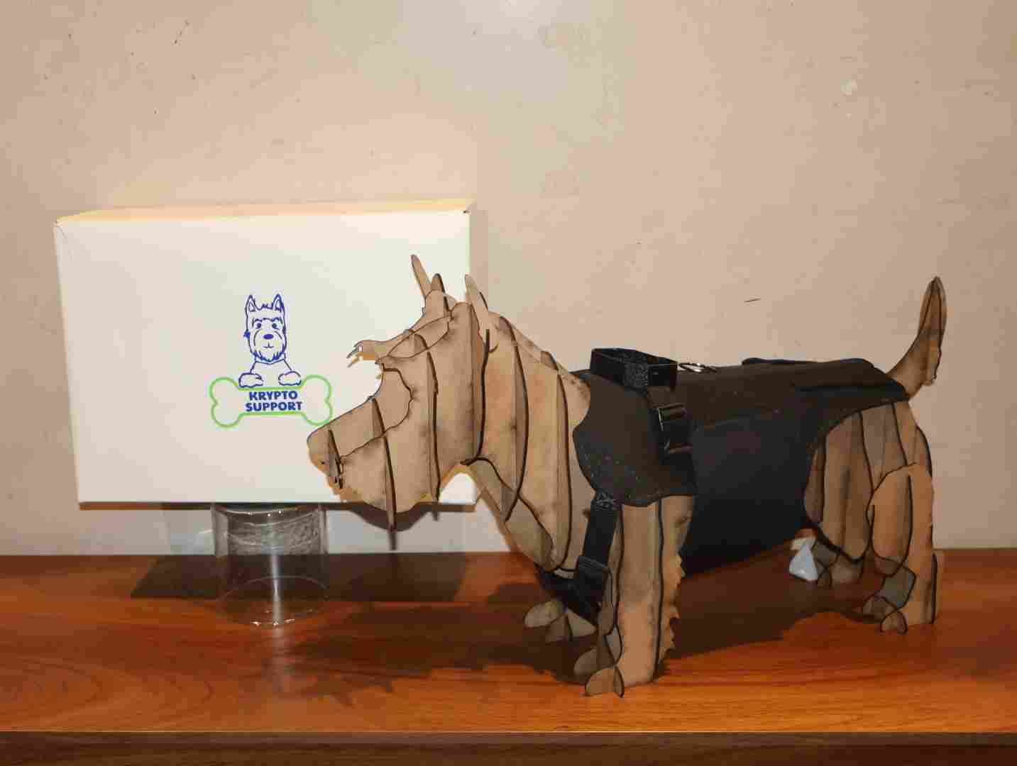
Packaging shot
Complete kit: brace, PCB module, packaging box.
Gallery
A full look at the project photoshoot.
What I would improve
Waterproofing the PCB enclosure — gasket seal on the lid and conformal coating on the PCB. On the firmware side, integrating Firebase Realtime Database for a persistent cloud dashboard accessible by the vet.
Bill of Materials
Components & materials
Everything used to build Krypto Support — electronics, hardware, and fabrication materials.
| # | Component | Qty | Role | Notes |
|---|---|---|---|---|
| 01 | XIAO ESP32-C6 | 1 | Main microcontroller | Wi-Fi AP + firmware host |
| 02 | MPU-6050 | 1 | IMU — pitch, roll, accel | I²C connection |
| 03 | TP4056 module | 1 | Li-Po battery charger | USB-C input, 1A charge |
| 04 | Li-Po battery 3.7V | 1 | Power supply | Specify capacity (mAh) |
| 05 | 100nF capacitor (1206) | 4 | Decoupling | SMD, near power pins |
| 06 | 10kΩ resistor (1206) | 2 | I²C pull-ups | SDA / SCL lines |
| 07 | Slide switch | 1 | Power on/off | Mounted on enclosure wall |
| 08 | FR1 copper-clad board | 1 | PCB substrate | 60×40mm, 1oz copper |
| 09 | Neoprene fabric | ~0.5m² | Brace body | 3mm thickness |
| 10 | ABS filament | ~50g | Buckles only | 1.75mm |
| 11 | TPU filament | ~120g | Hip support pads + PCB enclosure | 95A shore, 1.75mm |
| 12 | Vinyl sheet | ~A4 | Logo on packaging | Adhesive vinyl |
| 13 | Kraft board | 1 sheet | Packaging box | 2mm thickness |
| 14 | Hook & loop tape (Velcro) | ~30cm | Brace closure | 25mm wide |
Project Files
Download everything
All design files, firmware, and fabrication outputs packed in a single ZIP.