Week 10

Output Devices — OLED Display

PROTOCOL

I²C (0x3C)

CONTROLLER

SSD1306

This week I explored output devices — components that allow a microcontroller to communicate back to the physical world. I focused on a 0.96" I²C OLED display (SSD1306) for text and graphics output, connected to a XIAO RP2350.

RESOLUTION

128 × 64 px

LIBRARY

U8g2

Personal and Group Assignment

This week's personal assignment was to measure the wattage of different output devices.

Group Assignment

Here's the link to our group assignment of this week.

Introduction

What are output devices?

Output devices are components that allow a microcontroller to communicate information or produce effects in the physical world. While input devices capture data from the environment, output devices translate digital signals into something humans (or other systems) can perceive: light, sound, motion, or visual information.

Common output devices include LEDs, motors, servos, speakers, and displays. The key challenge is understanding each device's communication protocol, power requirements, and how to drive it correctly without damaging the microcontroller or the component itself.

OLED Display

SSD1306
128×64px · I²C · 0x3C

About the SSD1306 OLED

The 0.96" OLED display uses the SSD1306 controller chip and communicates over I²C — the same protocol used by the MPU-6050 in the previous week. It has a resolution of 128×64 pixels with each pixel being individually switchable, producing sharp, high-contrast visuals with no backlight needed (the pixels emit their own light).

OLEDs are preferred over traditional LCD screens in embedded projects because they have lower power consumption, better contrast ratios, wider viewing angles, and no need for a backlight driver. The U8g2 library provides a wide range of fonts, shapes, and drawing functions that work across many display controllers including the SSD1306.

Technical Specifications — OLED Display
ParameterValue
ControllerSSD1306
Resolution128 × 64 pixels
Display Size0.96 inches diagonal
Display TypeMonochrome OLED (white or blue)
Operating Voltage3.3V – 5V (onboard regulator)
Current Consumption~20 mA (typical)
Communication ProtocolI²C
I²C Address0x3C (most modules) / 0x3D
LibraryU8g2 (by olikraus)
Pinout & Wiring
VCC
Power supply
3.3V – 5V
GND
Common ground
GND
SDA
I²C data line
XIAO SDA (D4)
SCL
I²C clock line
XIAO SCL (D5)

The XIAO RP2350 has dedicated SDA (D4) and SCL (D5) pins for I²C. Multiple devices can share the same bus simultaneously since they each have unique addresses (0x3C for OLED, 0x68 for MPU-6050, etc.).

cont

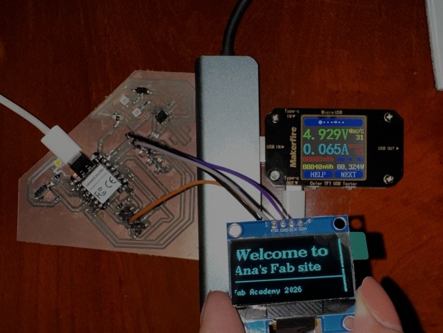
OLED connected via I²C (SDA=D4 / SCL=D5)

1txt

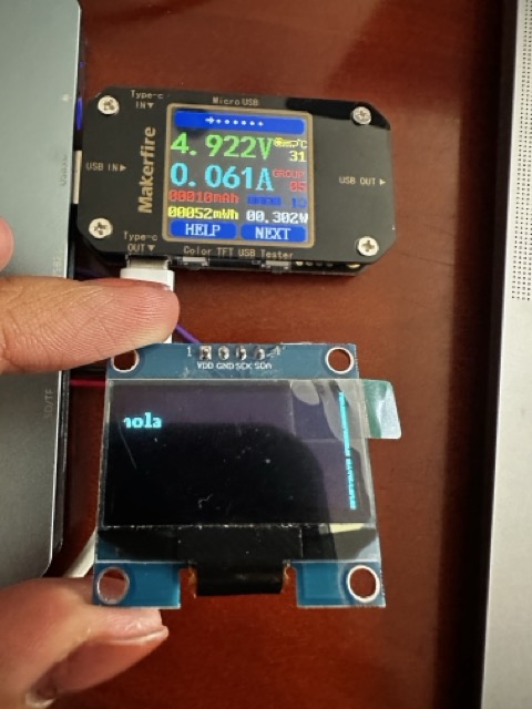
First text displayed on screen

Setup Process

library

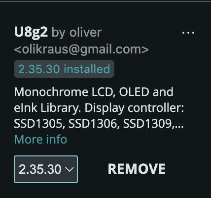
1. Library Installation

Installed the U8g2 library by olikraus from the Arduino Library Manager. U8g2 supports a wide range of display controllers including the SSD1306 and does not require a separate graphics library.
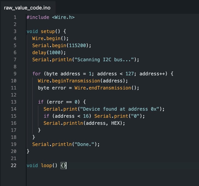
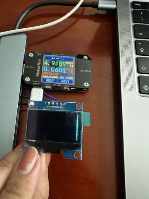
I2C address scan

2. I²C Address Scan

Ran an I²C scanner sketch to confirm the display's address (0x3C). This step is important — if the address in the code doesn't match the hardware, the display won't initialize.

fintxt

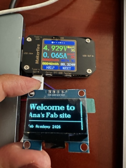
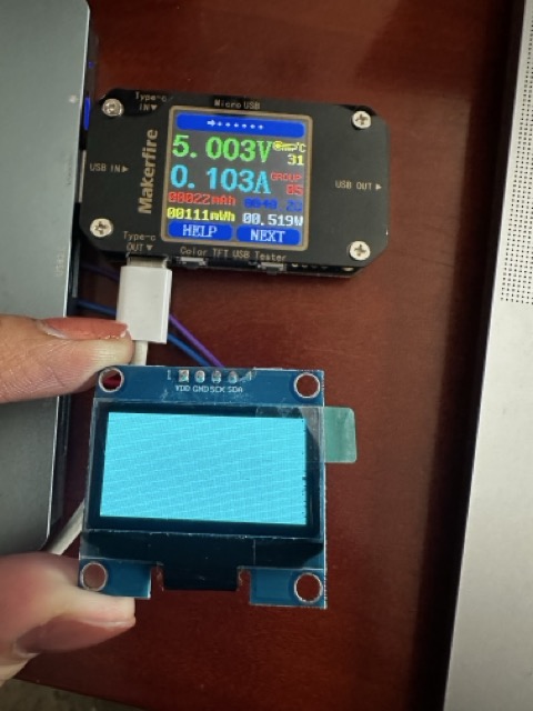
3. First Display Output

Initialized the display using the U8g2 constructor for the SSD1306 and wrote custom code to display the welcome message with different font sizes.

Code

Basic Text & Graphics — U8g2 Library
// week10_oled_u8g2.ino
#include <Arduino.h>
#include <U8g2lib.h>
#include <Wire.h>

// SSD1306 128x64 — I2C, hardware I2C, no reset pin
U8G2_SSD1306_128X64_NONAME_F_HW_I2C u8g2(U8G2_R0, /* reset= */ U8X8_PIN_NONE);

void setup() {
  u8g2.begin();
  u8g2.clearBuffer();

  u8g2.setFont(u8g2_font_ncenB14_tr);
  u8g2.drawStr(0, 20, "Welcome to");

  u8g2.setFont(u8g2_font_ncenB10_tr);
  u8g2.drawStr(0, 38, "Ana's Fab site");

  u8g2.drawHLine(0, 46, 128);

  u8g2.setFont(u8g2_font_5x7_tr);
  u8g2.drawStr(0, 62, "Fab Academy 2026");

  u8g2.sendBuffer();
}

void loop() {}

Power Measurement

Measuring wattage with a USB power meter

A key part of working with output devices is understanding how much power they consume. Knowing the wattage helps determine whether the XIAO RP2350 can power the device directly from USB, or whether an external power supply is needed.

Power in watts is calculated as P = V × I. A USB power meter placed between the USB source and the XIAO measures both values simultaneously and calculates wattage in real time.

usbm
Measurement Setup
  • 1
    Plug the USB power meter between the USB power source (laptop or charger) and the XIAO RP2350's USB-C port.
  • 2
    Record the baseline first — XIAO powered on with no output device connected, running a simple empty loop (~0.03–0.05W).
  • 3
    Test each state: OLED off (black), text display (~30% pixels), and full white screen.
  • 4
    Calculate net device consumption by subtracting the baseline reading from each measurement.
OLED — Measurements

OLED Display — Power Results

OLED displays are inherently efficient — only lit pixels consume power. A completely black screen draws almost nothing, while a fully white screen (all pixels on) reaches peak consumption.

black screen

OLED initialized but showing black (no pixels lit)

full white

All 128×64 pixels lit — maximum draw

Test Condition Voltage (V) Current (A) Power (W) Notes
XIAO idle (baseline)4.918 V0.031 A0.152 WNo output device connected
OLED initialized, black screen4.918 V0.060 A0.295 Wu8g2.clearBuffer() + sendBuffer()
OLED showing text (~30% pixels lit)4.929 V0.065 A0.320 WTypical UI, dark background
OLED full white (all pixels on)5.003 V0.103 A0.515 WdrawBox(0,0,128,64)
text display

Text Display (~30% pixels)

Typical operating condition — dark background with white text. Very close to the idle value since most pixels remain off.

full white

Full White Screen

Worst-case scenario. All 8,192 pixels lit simultaneously — useful to know the absolute maximum draw.

Power Formula — P = V × I

Every measurement follows the same fundamental relationship: Power (W) = Voltage (V) × Current (A). Since USB supplies a nominal 5V, the wattage is essentially 5 times the current reading in amps. The XIAO RP2350 is rated for up to 500mA from USB (2.5W total budget) — knowing the OLED's draw tells you exactly how much remains for sensors and other peripherals.

PCB board