Personal and Group Assignment
This week's personal assignment was to design a circuit, run a simulation and design the PCB, while document the process.
Group Assignment
Here's the link to our group assignment of this week.
Introduction
What are input devices?
Input devices are sensors or modules that capture information from the physical world and convert it into digital or analog signals that a microcontroller can read and process. They are the "senses" of any embedded system — without inputs, a microcontroller cannot react to its environment.
Examples of input devices include buttons, potentiometers, temperature sensors, light sensors, cameras, microphones, and inertial measurement units (IMUs) like the MPU-6050 used this week. The key challenge when working with inputs is understanding the data format, the reading protocol, and how to interpret raw values into meaningful physical quantities.
Why the MPU-6050?
The MPU-6050 is one of the most widely used IMUs in the maker and engineering community. It packs a 3-axis accelerometer and a 3-axis gyroscope into a single tiny chip, communicates over I2C (only 2 wires for data), and has excellent library support for Arduino. It's the perfect sensor to explore digital communication protocols, multi-axis data reading, and physical motion interpretation — all in one device.
The Sensor
MPU-6050 Overview
The MPU-6050 is a 6-DOF Inertial Measurement Unit manufactured by InvenSense (now TDK). It integrates a 3-axis MEMS accelerometer and a 3-axis MEMS gyroscope on the same silicon die, along with an onboard Digital Motion Processor (DMP) capable of running sensor fusion algorithms directly on the chip — offloading that computation from the main microcontroller.
The accelerometer measures linear acceleration (including gravity), while the gyroscope measures angular velocity. Used together with filtering techniques, they allow accurate estimation of orientation and motion in 3D space.
Technical Specifications
| Parameter | Value |
|---|---|
| Manufacturer | InvenSense (TDK) |
| Operating Voltage | 2.375 – 3.46V (breakout module: 3.3V – 5V) |
| Current Consumption | 3.9 mA (active) / 5 uA (sleep mode) |
| Accelerometer Range | +/-2g / +/-4g / +/-8g / +/-16g (configurable) |
| Gyroscope Range | +/-250 / +/-500 / +/-1000 / +/-2000 deg/s (configurable) |
| ADC Resolution | 16-bit per axis |
| Communication Protocol | I2C (up to 400 kHz) / SPI |
| I2C Address | 0x68 (AD0 = LOW) / 0x69 (AD0 = HIGH) |
| Onboard DMP | Yes — quaternion output, gesture detection |
| Operating Temperature | -40C to +85C |
| Module Dimensions | 20.3 x 15.6 mm |
Pinout
| MPU-6050 Pin | Function | Connected to |
|---|---|---|
| VCC | Module power supply (3.3V – 5V) | XIAO 3.3V |
| GND | Ground / reference (0V) | XIAO GND |
| SDA | I2C data line | XIAO D4 (GPIO 6) |
| SCL | I2C clock line | XIAO D5 (GPIO 7) |
| AD0 | I2C address select (LOW = 0x68) | GND |
| INT | Interrupt output (optional) | Not connected |
| XDA / XCL | Auxiliary I2C bus (optional) | Not connected |
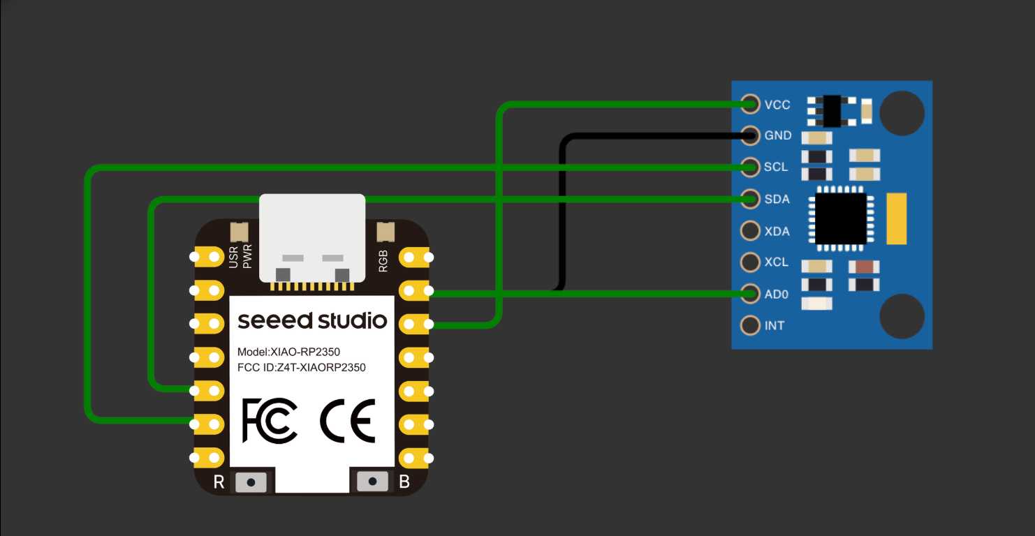
Wiring
Connecting MPU-6050 to XIAO RP2350
The MPU-6050 uses the I2C protocol, which requires only two data lines: SDA (data) and SCL (clock). On the Seeed XIAO RP2350, the dedicated I2C pins are D4 (SDA) and D5 (SCL), mapped to GPIO 6 and GPIO 7. The module is powered from the 3.3V pin — no level shifting needed since the XIAO RP2350 is a 3.3V device.
When AD0 is connected to GND, the I2C address is 0x68. Connecting it to 3.3V changes the address to 0x69, allowing two MPU-6050 modules on the same I2C bus simultaneously.
Connection Diagram
| MPU-6050 Pin | XIAO RP2350 Pin | Note |
|---|---|---|
| VCC | 3.3V | XIAO is 3.3V — no regulator needed |
| GND | GND | Common ground |
| SDA | D4 (GPIO 6) | I2C data line |
| SCL | D5 (GPIO 7) | I2C clock line |
| AD0 | GND | Sets I2C address to 0x68 |
| INT | Not connected | Optional interrupt output |
Important Note
The XIAO RP2350 operates at 3.3V logic — this is a perfect match for the MPU-6050, which also runs at 3.3V natively. No level shifting or onboard regulator is needed. Connect VCC directly to the XIAO's 3.3V pin. Avoid connecting to the 5V (VBUS) pin as it could damage the sensor.
Code
Library Setup
To interface the MPU-6050 with the XIAO RP2350 using the Arduino framework, I used the MPU6050 library by Electronic Cats (based on Jeff Rowberg's original work), along with the built-in Wire.h for I2C communication. The XIAO RP2350 is fully compatible with Arduino IDE using the Raspberry Pi Pico board package.
- 1In Arduino IDE, go to Preferences and add https://github.com/earlephilhower/arduino-pico/releases/download/global/package_rp2040_index.json to Board Manager URLs
- 2Install "Raspberry Pi Pico/RP2040" board package and select Seeed XIAO RP2350
- 3Search for "MPU6050" by Electronic Cats in Library Manager and click Install
- 4Also install the dependency "I2Cdev" if prompted
- 5Verify: File, Examples, MPU6050, MPU6050_raw
Accelerometer & Gyroscope
#include <Wire.h>
#include <MPU6050.h>

MPU6050 mpu;

void setup() {
  Serial.begin(115200);
  Wire.begin();           // Initialize I2C — uses D4/D5 on XIAO RP2350
  mpu.initialize();       // Wake up the MPU-6050

  if (mpu.testConnection()) {
    Serial.println("MPU-6050 connected!");
  } else {
    Serial.println("Connection failed. Check wiring.");
  }

  // Set accelerometer range: +/-2g
  mpu.setFullScaleAccelRange(MPU6050_ACCEL_FS_2);
  // Set gyroscope range: +/-250 deg/s
  mpu.setFullScaleGyroRange(MPU6050_GYRO_FS_250);
}

void loop() {
  int16_t ax, ay, az;
  int16_t gx, gy, gz;

  // Read all 6 axes in one call
  mpu.getMotion6(&ax, &ay, &az, &gx, &gy, &gz);

  // Convert raw values to real units
  // Accel sensitivity at +/-2g = 16384 LSB/g
  float accel_x = ax / 16384.0;
  float accel_y = ay / 16384.0;
  float accel_z = az / 16384.0;

  // Gyro sensitivity at +/-250 deg/s = 131 LSB/deg/s
  float gyro_x = gx / 131.0;
  float gyro_y = gy / 131.0;
  float gyro_z = gz / 131.0;

  Serial.print("Accel (g)  X:"); Serial.print(accel_x);
  Serial.print("  Y:");       Serial.print(accel_y);
  Serial.print("  Z:");       Serial.println(accel_z);

  Serial.print("Gyro(d/s)  X:"); Serial.print(gyro_x);
  Serial.print("  Y:");         Serial.print(gyro_y);
  Serial.print("  Z:");         Serial.println(gyro_z);

  Serial.println("---");
  delay(200);
}
Results
Observed Behavior
After uploading the code and opening the Serial Monitor, the MPU-6050 responded immediately with readings. When the sensor was flat on the desk, the Z-axis of the accelerometer read approximately 1g due to Earth's gravity, while X and Y remained close to zero. Tilting the module caused the gravity vector to distribute across the axes — which is exactly the principle behind tilt sensing.
The gyroscope produced values close to zero when stationary (with a small amount of noise, called gyro drift). Significant values only appeared during active rotation. This confirmed that the gyroscope measures angular velocity, not position — and integrating over time to get angle accumulates error.
Accelerometer vs Gyroscope
The accelerometer is well-suited for measuring static tilt angles because gravity provides a stable reference — but it's sensitive to vibrations and sudden shocks, which produce noisy readings.
The gyroscope delivers smooth, low-noise angular velocity data during motion, but its readings drift over time when integrated to compute angle — errors accumulate. The industry-standard solution (used in phones, drones, and game controllers) combines both sensors through a complementary filter or Kalman filter, achieving stable and accurate orientation estimates.
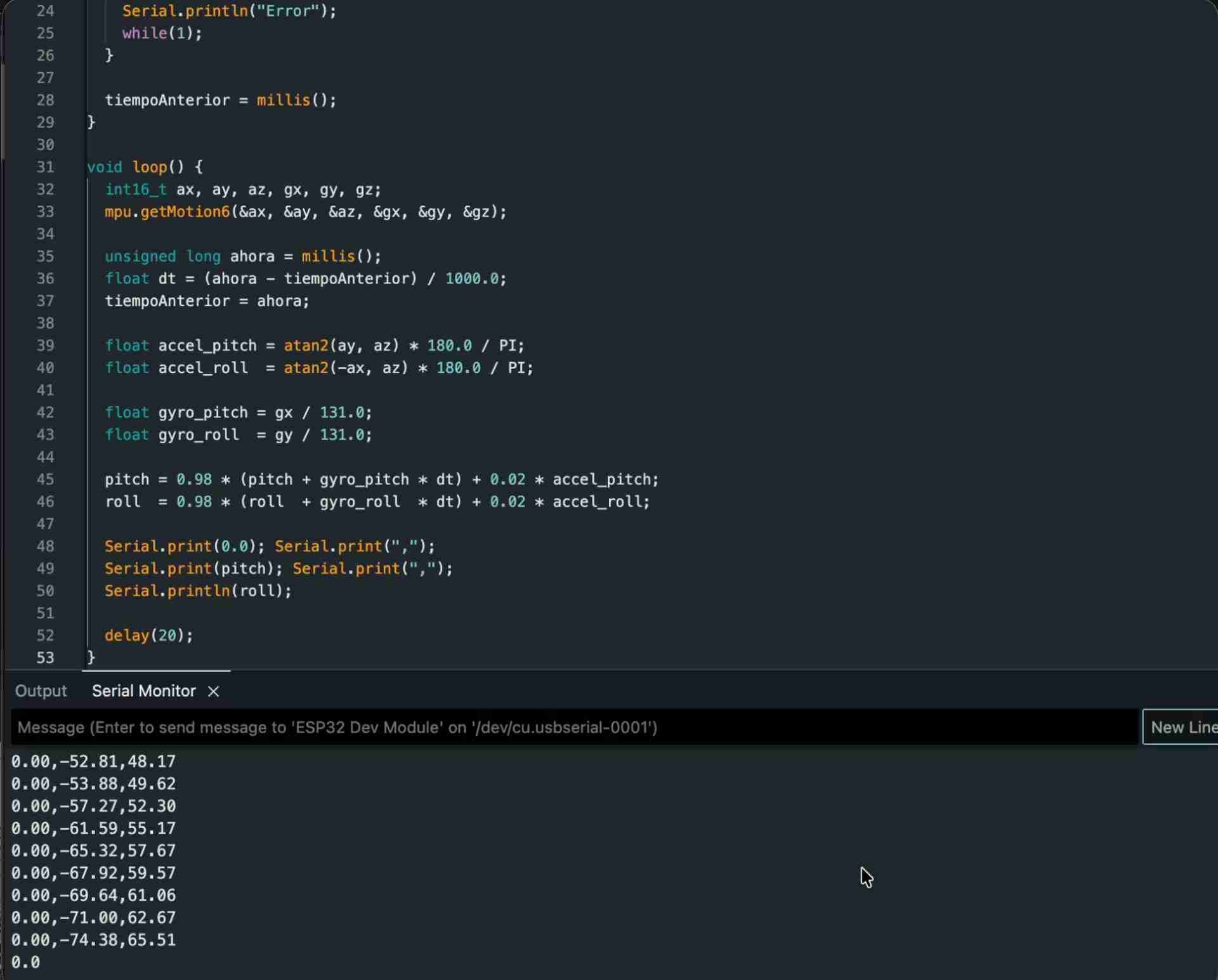
Readings from the Sensor